Insys 11-02-01-03-01.038 User manual
- Category
- Modems
- Type
- User manual
This manual is also suitable for

Manual
INSYS GSM 4.2 I4
Dez-06

Copyright © December 06 INSYS MICROELECTRONICS GmbH
Any duplication of this manual is prohibited. All rights on this documentation and the
devices are with INSYS MICROELECTRONICS GmbH Regensburg.
Restrictions of guarantee
This handbook contains a concise description. The compilation of the text has been made
with the utmost care. Despite all efforts, there may be deviations compared with the ac-
tual functions. No guarantee can therefore be given for the accuracy of the contents. We
can neither take over a legal responsibility nor any liability for incorrect information and
their consequences. Suggestions for improvements and comments are gladly accepted.
Trademarks
The use of a trademark not shown below is not an indication that it is freely available for
use.
MNP is a registered trademark of Microcom Inc.
IBM PC, AT, XT are registered trademarks of International Business Machine Corporation.
INSYS ® is a registered trademark of INSYS MICROELECTRONICS GmbH.
Windows™ is a registered trademark of Microsoft Corporation.
Publisher:
INSYS MICROELECTRONICS GmbH
Waffnergasse 8
D-93047 Regensburg, Germany
Phone: +49 (0)941/56 00 61
Fax: +49 (0)941/56 34 71
e-mail: [email protected]
Internet: http://www.insys-tec.de
Subject to technical changes as well as correction.
Date: Dec-06
Item: 31-22-03.078 english
Version: 1.0
Language: EN

Contents
Dez-06 3
1 INTRODUCTION.......................................................... 7
2 OVERVIEW................................................................ 10
2.1
INSYS GSM 4.2
I4 ................................................................. 11
2.2
D
ATA
S
ERVICES
........................................................................11
2.2.1
Data services via the serial interface................................................11
2.2.2
Data Connection via the GSM network............................................11
2.3
A
DDITIONAL
F
UNCTIONS
........................................................... 12
2.4
T
ECHNICAL
D
ATA
...................................................................... 13
2.4.1
Mechanical characteristics................................................................13
2.4.2
Power supply.....................................................................................13
2.4.3
Serial interface RS232 (V.24) ............................................................14
2.4.4
SIM card.............................................................................................14
2.4.5
Audio interface .................................................................................15
2.4.6
Antenna interface.............................................................................15
2.4.7
Digital inputs.....................................................................................15
2.4.8
Terminal Layout ................................................................................16
2.5
E
NVIRONMENTAL
C
ONDITIONS
................................................... 17
2.6
C
ERTIFICATIONS
....................................................................... 17
2.7
I
NTERFACES
,
D
ISPLAY AND
C
ONTROL
E
LEMENTS
............................ 18
2.7.1
Display elements...............................................................................18
2.7.2
Reset key...........................................................................................19
3 INITIAL OPERATION.................................................. 20
3.1
C
HECK THE SCOPE OF DELIVERY
................................................... 20
3.2
I
NSTALLATION
O
VERVIEW
.......................................................... 20
3.3
I
MPLEMENTATION
O
VERVIEW
..................................................... 21
3.4
S
WITCH THE
D
EVICE ON AND
T
EST IT
...........................................21

Contents
4
Dez-06
3.5
I
NITIAL
C
ONFIGURATION
............................................................22
3.5.1
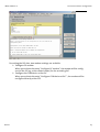
Initial configuration via HSComm GSM 4.2.x I4...............................22
3.5.2
Initial configuration with AT commands..........................................24
3.6
R
ESTART
................................................................................. 24
3.6.1
Procedure: Insert SIM card................................................................24
3.7
C
ONNECTION
T
EST
.................................................................... 25
3.8
C
AUSES OF
E
RROR DURING
I
MPLEMENTATION
...............................26
3.9
T
ESTING THE
S
IGNAL
Q
UALITY
.................................................... 26
3.10
C
HECKING THE
PIN
AND THE
L
OGIN
S
TATE
................................... 27
4 OPERATING MODES ................................................. 29
4.1
C
ONNECTION MODE
(
ONLINE
)..................................................... 29
4.2
C
OMMAND
M
ODE
.................................................................... 30
4.2.1
Offline command mode....................................................................30
4.2.2
Online command mode (local) .........................................................30
4.2.3
Remote configuration.......................................................................30
4.2.4
SMS configuration ............................................................................31
4.3
A
LARM
S
TATE
..........................................................................31
4.4
AT
C
OMMANDS FOR
S
WITCHING INTO ANOTHER
O
PERATING
M
ODE
31
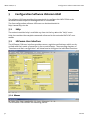
5 CONFIGURATION SOFTWARE HSCOMM GSM ......... 32
5.1
H
ELP
......................................................................................32
5.2
HSC
OMM
U
SER
I
NTERFACE
........................................................ 32
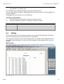
5.2.1
Menus................................................................................................32
5.2.2
Buttons..............................................................................................34
5.2.3
Status bar ..........................................................................................35
5.2.4
Tabs ...................................................................................................35

Contents
Dez-06 5
6 FUNCTIONS AND THEIR CONFIGURATION............... 36
6.1
P
ROCEDURES
:
C
ONFIGURE THE BASIC SETTINGS
............................. 36
6.1.1
GSM connection................................................................................36
6.1.2
DTMF tone processing.......................................................................38
6.1.3
Connection attempts ........................................................................38
6.1.4
Auto answer......................................................................................39
6.1.5
System monitoring ...........................................................................39
6.1.6
Date/Time .........................................................................................41
6.1.7
Serial interface of the device............................................................41
6.1.8
Protocol .............................................................................................42
6.1.9
Handshake ........................................................................................42
6.1.10
DTR behavior.....................................................................................42
6.2
SMS ...................................................................................... 43
6.2.1
Requirements for receiving an SMS .................................................43
6.2.2
Receiving SMS...................................................................................44
6.2.3
Automatic SMS processing ...............................................................44
6.2.4
Commands via SMS...........................................................................45
6.2.5
SMS acknowledgement ....................................................................46
6.2.6
Requirements for sending an SMS ...................................................46
6.2.7
Send and receive SMS .......................................................................47
6.2.8
SMS Dispatch to fax and e-mail........................................................48
6.2.9
Example: Free SMS dispatch via AT commands ...............................49
6.3
A
LARM
F
UNCTIONALITY
.............................................................50
6.3.1
Querying the alarm inputs................................................................50
6.3.2
Alarm types.......................................................................................50
6.3.3
Possible reactions to incoming alarms.............................................51
6.3.4
Possible recipients of an alarm message..........................................52
6.3.5
Processing of the alarm messages....................................................52
6.3.6
Main recipient and additional recipients .........................................53
6.3.7
Configure alarms...............................................................................53
6.3.8
Selective call answer.........................................................................56
6.3.9
Passwords and DTMF PIN..................................................................57
6.3.10
Security callback ...............................................................................58
6.4
H
ISTORY
................................................................................. 59

Contents
6
Dez-06
6.5
A
UDIO
I
NTERFACE AND
V
OICE
C
ONNECTIONS
...............................61
6.6
F
LASH UPDATE
.........................................................................61
6.7
O
PERATION WITH
PLC
S
.............................................................62
7 AT COMMAND SETS ................................................. 65
7.1
S
HORT
D
ESCRIPTION
INSYS
AT
C
OMMANDS
...............................67
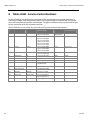
8 TABLE: GSM - SERVICE CENTER NUMBERS ............... 71

INSYS GSM 4.2 I4 Introduction
Dez-06 7
1 Introduction
Validity range of the manual
This user manual applies to the device INSYS GSM 4.2 I4.
Purpose
This manual is directed primarily at technical staff, in particular:
Programmers
Implementers
Required basics
General knowledge regarding communication technologies is required.
Safety Instructions
This manual includes notes which must be observed in order to avoid material damage.
The warnings and cautions are described as follows:
Caution - Damage of components!
Not observing this note may result in destruction of the device.
Warning!
Not observing this warning may result in malfunction.
Note
Notes contain important information which you should observe in par-
ticular.
Warning!
The device may only be used for the cases of application provided in
the manual.
Online availability
The manuals are available in German and English at http://www.insys-tec.de.

INSYS GSM 4.2 I4 Introduction
8
Dez-06
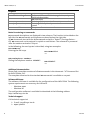
Emphasis
Representation
Meaning
"Basic settings" Software HSComm GUI texts, e.g. button, entry
field, tab description
AT
AT command
<expression>
Entering of the parameter for an AT command
[expression
]
Entering of the optional parameter for an AT com-
mand
OK
Response of an AT command
Notes for entering AT commands
AT command descriptions are displayed in two columns. The function is described on the
left side; the AT commands and responses are described on the right side.
All AT commands start with the letters AT and end with a “Return” (Carriage Return -
CR). AT commands can be entered in capital or small letters. The command is processed
after the modem received a CR input.
In the following, the used syntax is described, using two examples:
AT+CPIN=<n>
Entering the PIN 1234:
AT+CPIN=1234
OK
ATD<telephone number>
Dialing the telephone number 1234567.
ATD1234567
OK
Additional documentation
Please find a complete overview of all AT commands in the document: "AT Command Set
for INSYS GSM 4.2 I4".
The complete reference for the standard AT commands is available on request.
Software HSComm
The software HSComm is available for the configuration of the INSYS GSM. The following
system requirements are necessary for HSComm:
- Windows 2000
- Windows XP
The configuration software is available for download at the following address:
http://www.insys-tec.de
Technical support
Call technical support at:
E-mail: [email protected]
0941/560061

INSYS GSM 4.2 I4 Introduction
Dez-06 9
Taking back legacy systems
According to the new WEEE guidelines, the taking back and recycling of legacy systems
for our clients is regulated as follows:
Please send those legacy systems to the following address, carriage prepaid:
Frankenberg-Metalle
Gärtnersleite 8
D-96450 Coburg
This regulation applies to all devices which were delivered after August 13, 2005.

INSYS GSM 4.2 I4 Overview
10
Dez-06
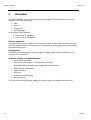
2 Overview
The INSYS GSM 4.2 I4 is a terminal device according to ETSI GSM Phase 2/2+ for the
transmission of the following:
Data
Voice
Fax group 3
SMS messages
In dual band GSM networks:
Class 4 (2W @ 900Mhz)
Class 1 (1W @ 1.800MHz)
Fields of application
The device offers several options for transmitting data via the GSM network. You may
use it to implement data connections or, for example, a messaging system with precon-
figured message texts.
Configuration
The device can be configured easily using the configuration software HSComm, or di-
rectly via AT commands.
Interfaces, Display and Control Elements
Serial RS232 Interface
Slot for the SIM card of a GSM provider (3 V cards)
Miniature SIM card reader with integrated compartment
FME antenna connection
Audio interface
Reset key
6 LEDs for status display
4 alarm inputs
The connections for the power supply, the alarm inputs are designed as terminals.

INSYS GSM 4.2 I4 Overview
Dez-06 11
2.1 INSYS GSM 4.2 I4
2.2 Data Services
2.2.1 Data services via the serial interface
The serial interface is available for the configuration of the device or for the data connec-
tion to the terminal device.
The serial interface has the following characteristics:
Interface terminal adapter (TA) – terminal station (terminal equipment, TE)
Compatible with RS232 (V.24/V.28)
Extended data formats (10 and 11 bit)
Baud rates: 300, 600, 1200, 2400, 4800, 9600, 14400, 19200, 28800, 38400, 57600,
115200 bps
The standard setting is 19200 bps
No automatic baud rate adaptation (command AT**BAUD)
2.2.2 Data Connection via the GSM network
The device is designed for the system environment of mobile networks with 900 MHz
and 1800 MHz according to ETSI GSM phase 2/2+. Accessing a GSM network requires a
SIM card of a network provider.
The data connection has the following characteristics:
Non-transparent asynchronous
V.22bis (2,400 bps)
V.32/V.33/V.34 (4800/9600/14400 bps)
V.110 (2400/4800/9600/14400 bps)
The device masters the following data services. The support of some data services in the
GSM network depends on the GSM provider.
Data connection

INSYS GSM 4.2 I4 Overview
12
Dez-06
Voice connection
HR, FR, EFR
Fax transparent
Group 3: Class 1 and Class 2
SMS services
2.3 Additional Functions
The device provides the following:
Integrated real time clock (RTC)
Event memory (history function) with 200 entries
Flash update option (local or remote)
The device offers the following functions:
Security and Access Protection
Password protection for
o Incoming data connections
o Security callback
o Commands via SMS
o Operation via DTMF
o Remote configuration
Selective call acceptance (CLIP)
Connection Setup and Monitoring
Periodic alive SMS for operation monitoring
After any power failure that lasts a minimum of 5 seconds (not reset), the device
can send a power up SMS.
Automatic re-login into the GSM network after power failures
Scheduled logout/login into the GSM network
Control via AT commands
Locally (via terminal)
Remotely (only extended command set)
Via SMS (only extended command set)
Alarm input
Usage as alarm or pulse input with 10 different pulse sequences
Sending alarm messages via SMS, fax, e-mail and via data connection, or estab-
lishing a voice connection
Additional dispatch of the alarm message to up to 10 further recipients from a
pool of 20 numbers

INSYS GSM 4.2 I4 Overview
Dez-06 13
2.4 Technical Data
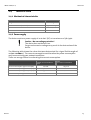
2.4.1 Mechanical characteristics
INSYS GSM 4.2 I4
Weight 270 g
Dimensions in mm (w x l x h) 55 x 110 x 75
Protection class cover front IP 40
Protection class terminals IP 20
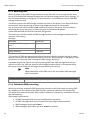
2.4.2 Power supply
The device requires a power supply of 10 to 60 V (DC) at a maximum of 5% ripple.
Caution - No overvoltage protection!
The device does not have a fuse.
Surges and excessive voltages may result in the destruction of the
device.
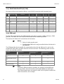
The following table shows the values that were determined for a signal field strength of
20 (AT**SIGNAL?). The current consumption and therefore the power consumption
may increase during poor network conditions.
These are average values for estimating the current consumption.
State:
Logged into the GSM net-
work
State:
Connection established
Current consumption type at 10 V (DC)
170 mA 245 mA
Current consumption type at 24 V (DC)
90 mA 110 mA
Current consumption type at 36 V (DC)
55 mA 70 mA
Power consumption approx. 1.7 W 2.1 W

INSYS GSM 4.2 I4 Overview
14
Dez-06
2.4.3 Serial interface RS232 (V.24)
Pin layout of the serial interface RS232, 9-pin SUB-D connector with threaded joint:
Pin Description Function
CCITT
V.24
EIA
RS232
DIN
66020
E/A DCE to
DTE
1 DCD Data Carrier Detect 109 CF M5 O
2 RXD Receive Data 104 BB D2 O
3 TXD Transmit Data 103 BA D1 I
4 DTR Data Terminal Ready 108 CD S1 I
5 GND Ground 102 AB E2
6 DSR Data set ready 107 CC M1 O
7 RTS Request to send 105 CA S2 I
8 CTS Clear To Send 106 CB M2 O
9 RI Ring Indication 125 CE M3 O
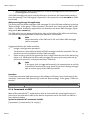
2.4.4 SIM card
For the data connection to the GSM network, the device requires a SIM card from a GSM
provider. The SIM card is the identification towards the network provider.
The slot for the SIM card is on the front of the device.
Notes:
Only 3V cards may be used.
Changing the SIM card is only permitted when the device is
switched off.
The GSM provider has to enable the requested services for the SIM card. A card can be
enabled for both voice and data services at the same time. The following cards and con-
tracts are normally available:
Function Prepaid card Contract for voice
transmission
Contract for data
transmission
Outgoing data connec-
tion
Incoming data connec-
tion
- -
SMS
Voice connection
-
Note
Generally, different phone numbers are assigned to the different
services (voice, data connections with 2400, 4800 and 9600 bps).
The GSM network does not switch a data call to a phone number for
voice connections, for example.

INSYS GSM 4.2 I4 Overview
Dez-06 15
2.4.5 Audio interface
Pin layout, 4-pin RJ45 phone plug:
Pin Usage
1 Microphone (-)
2 Speaker (-)
3 Speaker (+)
4 Microphone (+)
Reference type: Handset Siemens-Gigaset
2.4.6 Antenna interface
The antenna connector at the front of the device has the type FME (male).
All commercial GSM antennas with a female FME connector can be used as antennas.
Ensure that the frequency band corresponds with the one of the provider when using
single band antennas (900 MHz or 1800 MHz).
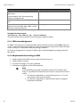
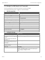
2.4.7 Digital inputs
Alarm input
The alarm inputs are designed as pull-up and are on HIGH in inactive, open state. The
alarm inputs are activated by connecting to ground.
LOW Active 0 to 1 V
HIGH Inactive 4 to 12 V
The input current from LOW to internal +5 V is typically 0.5 mA.

INSYS GSM 4.2 I4 Overview
16
Dez-06
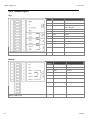
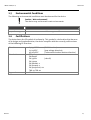
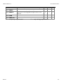
2.4.8 Terminal Layout
Top
Terminal
1 GND Ground
2 X1 reserved
3 10..60VDC Voltage Supply
10V - 60V DC
4 GND Ground
5 GND Ground
6 Reset Reset
7 GND Ground
8 Input 1 Alarminput 1
9 Input 2 Alarminput 2
10 GND Ground
INSYS GSM 4.2 I4
Bottom
Terminal
11 NC Not connected
12 NC Not connected
13 GND Ground
14 GND Ground
15 Input 3 Alarminput 3
16 Input 4 Alarminput 4
INSYS GSM 4.2 I4

INSYS GSM 4.2 I4 Overview
Dez-06 17
2.5 Environmental Conditions
The following environmental conditions must be observed for the device.
Caution - Wet environment!
The device may not be used in wet environments.
INSYS GSM 4.2 I4
Humidity 0 - 95% non-condensing
Temperature range 0°C to 55°C
2.6 Certifications
The device bears the CE symbol of conformity. This symbol is a declaration that because
of its design and implementation, the device complies with the currently valid versions
of the following EC directives:
Directives: 89/336/EEC (EMC directive)
73/23/EEC (Low voltage directive)
91/263/EEC (Telecommunications devices directive)
Standards:
ETS 300 342 1
EN 60950
EN 55022 (class B)
EN 55024
EN 300 607-1
EN 301 419-1
EN 3015011 V7.01
TBR 19, TBR 20
Approvals: CE

INSYS GSM 4.2 I4 Overview
18
Dez-06
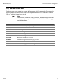
2.7 Interfaces, Display and Control Elements
The device has 6 LEDs for status displays and one reset key on the front.
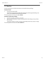
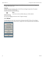
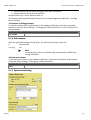
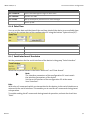
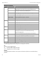
2.7.1 Display elements
Each device has 6 LEDs on the front.
LED Color On Off Blinking Flashing
Power Green Supply OK No supply
Status Yellow GSM engine
logged into
network*
GSM engine not
logged into
network*
Data connection
Alternate blinking
with LED Connect, or
LED DCD: Factory
settings loaded
Initialization,
Processing of
alarms
,
Dispatch of
periodic alive
SMS, SMS poll-
ing and power
up SMS
Connect Yellow Data connec-
tion established
No data connec-
tion established
Alternate blinking
with LED state: Fac-
tory settings loaded
RX Green Exchange of
data via RS232
No data ex-
change
TX Green Exchange of
data via RS232
No data ex-
change
Signal Green Best GSM signal
(field strength)*
GSM signal
(field strength)
too low*
Blinking interval
depending on GSM
signal (field
strength)*:
The higher the blink-
ing frequency, the
better the signal.
(see Chap. 3.9)
Blinking in intervals
of seconds during
the flash update
*) The periodical query of the login state and the GSM field strength must be active (command
AT**GSMREQ).

INSYS GSM 4.2 I4 Overview
Dez-06 19
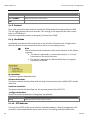
2.7.2 Reset key
Use the reset key to re-initialize the device or to load the factory settings.
Procedure: Reset
1. Press the reset key briefly.
The device is returned to its initial state. This process takes approximately 30 sec-
onds. The LED Status blinks during this period.
This corresponds to the command AT**RESET.
Procedure: Load factory settings
1. Press the reset key more than 25 seconds.
2. When the LEDs Connect or DCD and Status blink alternately you may release
the reset key.
The device executes a restart. If the pin of the SIM card has been saved, it is kept.
This corresponds to the command AT**DEFAULT.

INSYS GSM 4.2 I4 Initial Operation
20
Dez-06
3 Initial Operation
3.1 Check the scope of delivery
Check the scope of delivery before initial operation:
INSYS GSM 4.2 I4
9-pin serial cable for the connection between the PC and the device (RS232 cable)
Printed manual (German/English).
The latest editions of the manual and the AT command set are available for
download at our website: http://www.insys-tec.de.
Contact your supplier if the content is not complete.
Optional accessories:
GSM antenna (outside mounted antenna, patch antenna or magnetic base an-
tenna)
CD with configuration software HSComm (free) and manuals.
The configuration software is also available for download at our internet site:
http://www.insys-tec.de.
Check the device for shipping damage. Please also refer to your supplier if anything is
damaged.
Keep the packaging material for dispatch or storage.
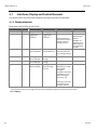
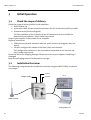
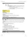
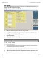
3.2 Installation Overview
The following image shows the installation overview using the INSYS GSM 4.2 I4 device
as example.
GSM antenna
Voltage supply Input 2
Input 1
Configuration PC
PLC
Page is loading ...
Page is loading ...
Page is loading ...
Page is loading ...
Page is loading ...
Page is loading ...
Page is loading ...
Page is loading ...
Page is loading ...
Page is loading ...
Page is loading ...
Page is loading ...
Page is loading ...
Page is loading ...
Page is loading ...
Page is loading ...
Page is loading ...
Page is loading ...
Page is loading ...
Page is loading ...
Page is loading ...
Page is loading ...
Page is loading ...
Page is loading ...
Page is loading ...
Page is loading ...
Page is loading ...
Page is loading ...
Page is loading ...
Page is loading ...
Page is loading ...
Page is loading ...
Page is loading ...
Page is loading ...
Page is loading ...
Page is loading ...
Page is loading ...
Page is loading ...
Page is loading ...
Page is loading ...
Page is loading ...
Page is loading ...
Page is loading ...
Page is loading ...
Page is loading ...
Page is loading ...
Page is loading ...
Page is loading ...
Page is loading ...
-
 1
1
-
 2
2
-
 3
3
-
 4
4
-
 5
5
-
 6
6
-
 7
7
-
 8
8
-
 9
9
-
 10
10
-
 11
11
-
 12
12
-
 13
13
-
 14
14
-
 15
15
-
 16
16
-
 17
17
-
 18
18
-
 19
19
-
 20
20
-
 21
21
-
 22
22
-
 23
23
-
 24
24
-
 25
25
-
 26
26
-
 27
27
-
 28
28
-
 29
29
-
 30
30
-
 31
31
-
 32
32
-
 33
33
-
 34
34
-
 35
35
-
 36
36
-
 37
37
-
 38
38
-
 39
39
-
 40
40
-
 41
41
-
 42
42
-
 43
43
-
 44
44
-
 45
45
-
 46
46
-
 47
47
-
 48
48
-
 49
49
-
 50
50
-
 51
51
-
 52
52
-
 53
53
-
 54
54
-
 55
55
-
 56
56
-
 57
57
-
 58
58
-
 59
59
-
 60
60
-
 61
61
-
 62
62
-
 63
63
-
 64
64
-
 65
65
-
 66
66
-
 67
67
-
 68
68
-
 69
69


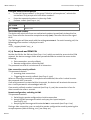
Insys 11-02-01-03-01.038 User manual
- Category
- Modems
- Type
- User manual
- This manual is also suitable for
Ask a question and I''ll find the answer in the document
Finding information in a document is now easier with AI
Related papers
-
Insys 2G (GSM) 4.2 Owner's manual
-
-
-
-
-
-
-
-
-
Other documents
-
Panasonic EBG500 Important information
-
Siemens Gigaset M1 professional User manual
-
Kärcher RDS1 SB-C SB-M Owner's manual
-
 BAB TECHNOLOGIE EIBPORT V3 Firmware Update Procedure
-
Alphatech Alpha Guard TC35 User manual
-
Fagor CNC 8050 OEM User manual
-
 GalileoSky gps light User manual
-
 Intab L-53 User manual
-
-
Eberspacher CALLTRONIC Owner's manual


