Page is loading ...

1
Quick Installation Guide
sales@ctcu.com
IGS-2408SM-24PH
IGS-2408SM-24PHE
24 x 10/100/1000Base-T(X) + 8 X 100/1000Base-X SFP with 24 x
PoE+ Managed Switch

1
Version 1.1 September, 2020
2020 CTC Union Technologies Co., LTD.
All trademarks are the property of their respective owners.
Technical information in this document is subject to change without notice.
CTC Union Technologies Co.,Ltd.
Far Eastern Vienna Technology Center
(Neihu Technology Park)
8F, No. 60 Zhouzi St.,
Neihu, Taipei 114, Taiwan

2
LEGAL
The information in this publication has been carefully checked and is believed to be entirely accurate at
the time of publication. CTC Union Technologies assumes no responsibility, however, for possible errors
or omissions, or for any consequences resulting from the use of the information contained herein. CTC
Union Technologies reserves the right to make changes in its products or product specifications with the
intent to improve function or design at any time and without notice and is not required to update this
documentation to reflect such changes.
CTC Union Technologies makes no warranty, representation, or guarantee regarding the suitability of its
products for any particular purpose, nor does CTC Union assume any liability arising out of the
application or use of any product and specifically disclaims any and all liability, including without
limitation any consequential or incidental damages.
CTC Union products are not designed, intended, or authorized for use in systems or applications
intended to support or sustain life, or for any other application in which the failure of the product could
create a situation where personal injury or death may occur. Should the Buyer purchase or use a CTC
Union product for any such unintended or unauthorized application, the Buyer shall indemnify and hold
CTC Union Technologies and its officers, employees, subsidiaries, affiliates, and distributors harmless
against all claims, costs, damages, expenses, and reasonable attorney fees arising out of, either directly
or indirectly, any claim of personal injury or death that may be associated with such unintended or
unauthorized use, even if such claim alleges that CTC Union Technologies was negligent regarding the
design or manufacture of said product.
WARNING:
This equipment has been tested and found to comply with the limits for a Class A digital device,
pursuant to Part 15 of the FCC Rules. These limits are designed to provide reasonable protection against
harmful interference when the equipment is operated in a commercial environment. This equipment
generates, uses, and can radiate radio frequency energy and if not installed and used in accordance with
the instruction manual may cause harmful interference in which case the user will be required to correct
the interference at his own expense. NOTICE: (1) The changes or modifications not expressively
approved by the party responsible for compliance could void the user's authority to operate the
equipment. (2) Shielded interface cables and AC power cord, if any, must be used in order to comply
with the emission limits.
This is a Class A product. In a domestic environment this product may cause radio interference in which
case the user may be required to take adequate measures.

4
Table of Contents
Introduction .................................................................................. 5
Package List ................................................................................. 5
Features ........................................................................................ 5
Access to Command Line Interface (CLI) ................................... 6
CONSOLE CONNECTION ......................................................................................... 6
TELNET/SSH CONNECTION .................................................................................... 7
Access to Web-Based Management Interface ............................ 8
Specifications ............................................................................... 9
ETHERNET INTERFACE............................................................................................ 9
OPTICAL ............................................................................................................ 9
SWITCH FEATURES ............................................................................................... 9
POWER OVER ETHERNET ........................................................................................ 9
POWER ............................................................................................................. 9
MECHANICAL ..................................................................................................... 10
ENVIRONMENTAL................................................................................................ 10
CERTIFICATIONS ................................................................................................. 10
MTBF (MIL-HDBK-217) ................................................................................... 10
Panels ......................................................................................... 11
LAN and Fiber Ports ................................................................... 12
PoE Ports .................................................................................... 12
RJ-45 ETHERNET PORT PINOUTS ............................................................................ 12
RJ-45 ETHERNET & POE PIN ASSIGNMENTS .............................................................. 12
CONSOLE Port ........................................................................... 13
RJ-45 TO DB-9 SIGNAL MAPPING .......................................................................... 13
Alarm Relay Connection ............................................................ 14
Earth Ground Connection .......................................................... 14
LED Indicators ............................................................................ 15
Installation .................................................................................. 16
Application .................................................................................. 17

5
Introduction
IGS-2408SM-24PH(E) are industrial grade managed Gigabit PoE
(Power over Ethernet) switches with 24 x 10/100/1000Mbps RJ-45 (with
Power over Ethernet function) + 8 x 100/1000Mbps SFP. Housed in
rugged enclosures, these switches are designed for harsh environments
where environmental conditions exceed commercial product
specifications, such as industrial networking or intelligent transportation
systems (ITS) and are also suitable for many Smart City, surveillance,
intelligent traffic control systems.
These switches are also rack-mountable in 19" rack and support L2
basic and advanced functions, such as ring redundancy (STP/RSTP/
MSTP/ERPS), proprietary u-ring redundancy, time synchronization
(PTPv2) and so on.
Package List
IGS-2408SM-24PH(E) device
Console cable (RJ-45 to DB-9)
19" rack-mount kit (brackets and screws)
Protective caps for SFP ports
Features
Redundant dual input power 48VDC (44~57VDC)
IP30 rugged metal housing protection & fanless
Wide temperature range -40°C~75°C (IGS-2408SM-24PHE)
Support many advanced Ethernet L2 functions
Support IEEE1588 PTPv2 for precise time synchronization
Console, Telnet, Web and SNMP management
Heavy Industrial grade EMS, EMI, Railway Traffic EN50121-4,
EN61000-6-2, EN61000-6-4

6
Access to Command Line Interface (CLI)
IGS-2408SM-24PH(E) models are managed Gigabit PoE switch
devices. Initial configuration (assignment of IP address) may be
accomplished via the RS-232 console and a PC or laptop running
terminal emulation software or via RJ45 Ethernet port running Telnet or
SSH.
Accessing the switch via CONSOLE or Ethernet port allows the user
to use Command Line Interface (CLI) to manage and configure the device.
This management method is relatively useful when you lose the network
connection to the device. In most configuration scenarios, the console
will only be used to initially configure the IP address, so that the device
may be accessed via the other methods which require working TCP/IP.
See below for useful information for accessing the device via console
and Telnet/SSH connection.
Console Connection
Use the provided accessory cable to connect the "CONSOLE" port
to the PC terminal communications port (DB9). Run any terminal
emulation program (HyperTerminal, PuTTY, TeraTerm Pro, etc.) and
configure the communication parameters as follows:
Speed:
115,200
Data:
8 bits
Parity:
None
Stop Bits:
1
Flow Control:
None
From a cold start, the following screen will be displayed. At the
"Username" prompt, enter “admin” with no password.
To change the default IP address to your desired one (for example,
192.168.0.10/24), issue the following commands:
For complete CLI operation, please refer to the operation manual.
#
# config terminal
(config)# interface vlan 1
(config-if-vlan)# ip address 192.168.0.10 255.255.255.0
Press ENTER to get started
Username: admin
Password:
#

7
Telnet/SSH Connection
To use Command Line Interface (CLI), you can also choose to
access the device through a Telnet/SSH connection via TCP/IP network
over Ethernet ports. For initial operation, use the default TCP/IP settings
(10.1.1.1) to login to the device.
Default TCP/IP settings:
IP Address:
10.1.1.1
Subnet Mask:
255.255.255.0
Username:
admin
Password:
No password (Press "Enter"
key)
To change the default IP address to your desired one (for example,
192.168.0.10/24), issue the following commands:
Once the desired IP address has been configured, a web browser
can be accessed and used to configure the device through a more easy-
to-use GUI (graphical user interface). For complete CLI operation, please
refer to the operation manual.
#
# config terminal
(config)# interface vlan 1
(config-if-vlan)# ip address 192.168.0.10 255.255.255.0

8
Access to Web-Based Management Interface
To enter the web-based management interface for the first time
or after returning the device back to factory defaults, input the default IP
address “10.1.1.1” in your web browser. Then, a standard login prompt
will appear depending on the type of browser used. The example below
is with Firefox browser.
Enter the factory default username “admin” with no password.
After successfully entering the web based management, the Port State
page will appear. For complete Web GUI operation, please refer to the
operation manual.

9
Specifications
Ethernet Interface
Standards: IEEE802.3 (10Base-T), 802.3u (100Base-TX), 802.3ab
(1000Base-T)
RJ-45 (shielded) Ports: 24 ports
Speed: 10/100/1000M (Auto)
Optical
Standards: IEEE80802.3u (100Base-FX), 802.3z (1000Base-X)
SFP-Based Slots: 8 slots
Speed: 100/1000M (Manual) dual speed
SFP slots support DDMI function
Switch Features
Store & Forward Switch
Supports IEEE802.3x Flow Control
Auto MDI/MDI-X
Duplex: Full/Half (Auto-negotiation per IEEE802.3u)
Switching Fabric: 64Gbps (Non-blocking)
MAC Address Table: 32K
Memory Buffer: 4M Bytes
Jumbo Frame: 10K Bytes
Power over Ethernet
PoE Ports:24
End Span Alternate A Mode
Supports IEEE802.3af 15.4watts PoE per port
Supports IEEE802.3at 30watts PoE+ per port
Maximum 400W total PoE output power budget (30W per port)
Positive (V+) pins 1,2; Negative (V-) pins 3,6; Data 1, 2, 3, 6, 4, 5, 7, 8
Power
Redundant Dual Input Power: 48VDC (44~57VDC)
50~57VDC is recommended for IEEE802.3at PoE+ 30W applications
Support Removable Terminal Block
Consumption: <30W (50VDC) without PoE load, <445W (50VDC) with
400W PoE load

10
Mechanical
Water & Dust Proof: IP30 Protection
Dimensions: 280 mm (D) x 440 mm (W) x 44 mm (H)
Mounting: 19" Rack Mounting
Weight: 4.26 kg
Environmental
Operating Temperature: -10°C~60°C (IGS-2408SM-24PH), -40°C~75°C
(IGS-2408SM-24PHE)
Storage Temperature: -40°C~85°C
Humidity: 5%~95% (Non-condensing)
Certifications
EMC: CE (EN55024, EN55032)
EMI (Electromagnetic Interference): FCC Part 15 Subpart B Class A, CE
Railway Traffic: EN50121-4
Immunity for Heavy Industrial Environment: EN61000-6-2
Emission for Heavy Industrial Environment: EN61000-6-4
EMS (Electromagnetic Susceptibility) Protection Level:
EN61000-4-2 (ESD) Level 3, Criteria B
EN61000-4-3 (RS) Level 3, Criteria A
EN61000-4-4 (Burst) Level 3, Criteria A
EN61000-4-5 (Surge) Level 3, Criteria B
EN61000-4-6 (CS) Level 3, Criteria A
EN61000-4-8 (PFMF, Magnetic Field) Field Strength: 300A/m,
Criteria A
Safety: UL60950-1, EN60950-1
4KV surge protection for UTP & fiber ports
Shock: IEC 60068-2-27
Freefall: IEC 60068-2-32
Vibration: IEC 60068-2-6
MTBF (MIL-HDBK-217)
97,078 Hours

11
Panels
No.
Description
1
UTP RJ-45 ports
2
Fiber optic SFP slots
3
Console port (RJ-45 to DB-9)
4
Power, Ring, ACT, ALM LED indicators
5
Link/ACT & Speed LED indicators for UTP RJ-45 &
fiber optic ports
6
PoE LED indicators
7
DC power supply
8
Alarm terminal block
9
Earth grounding
Figure 1. Front Panel
2
1
Figure 2. Rear Panel
3
6
5
4
8
9
7

12
LAN and Fiber Ports
IGS-2408SM-24PH(E) switches have 24 electrical LAN ports
(labeled 1~24) and 8 fiber ports (SFP based, labeled 25~32) on the front
panel. The LAN ports that utilize shielded RJ-45 connectors support
10/100/1000M; while the fiber SFP ports support 100/1000M.
PoE Ports
All 24 LAN ports support PoE (Power over Ethernet) per
IEEE802.3af (15.4W) or IEEE802.3at (30W) for connection to standard
PoE PD (Power Devices) such as IP Cameras, Access Points, IP Phones,
Digital Signage, etc. PoE eliminates the need to run separate power to
these devices thereby simplifying deployment and reducing expenses.
The LAN ports may also connect to any non-PoE device for normal
Ethernet transmission without any damage to the non-PoE device or to
this device.
RJ-45 Ethernet Port Pinouts
RJ-45 Ethernet & PoE Pin Assignments
Pin
No.
RJ-45 Ethernet
PoE Output
100Base-TX
1000Base-T
1
RX+
TRD 0+
V+
2
RX-
TRD 0-
V+
3
TX+
TRD 1+
V-
4
-
TRD 2+
5
-
TRD 2-
6
TX-
TRD 1-
V-
7
-
TRD 3+
8
-
TRD 3-

13
CONSOLE Port
The RJ-45 port labeled “CONSOLE” is an RS-232 terminal port for
local management. These models use a “light” CLI (Command Line
Interface) in addition to a user friendly Web interface and industry
standard SNMP.
One RJ-45 to DB-9 cable is provided with this device. CONSOLE
port pinouts and RS-232 DB-9 connector are illustrated below together
with RJ-45 to DB-9 signal mapping information. Use the supplied cable to
connect the RJ-45 CONSOLE port to a console PC.
Figure 3. CONSOLE Port Pinout Figure 4. RS-232 (Female) Pinout
RJ-45 to DB-9 Signal Mapping
DB-9 (Female)
Direction
RJ-45
Signal
Pin
Pin
Signal
RXD
2
3
TXD
TXD
3
6
RXD
GND
5
5
GND

14
Alarm Relay Connection
The alarm relay contact can be wired into an alarm circuit which
senses an alarm condition when the contact is broken. The alarm relay is
normally closed when there is no alarm condition. The alarm conditions
are user programmable through management to include power, link
faults or other fault conditions. Please note that the alarm relay contact
can only support 1A current at 24VDC. Do not apply voltage and current
that exceed these specifications.
Figure 5. Alarm Relay Wiring
Earth Ground Connection
An earth ground connector is provided on the rear panel with an
earth ground sign next to it. Grounding the device can help to release
leakage of electricity to the earth safely so as to reduce injuries from
electromagnetic interference (EMI).
Prior to connecting to the power, it is important to connect the ground
wire to the earth. Follow steps below to install ground wire:
1. Loosen or remove the grounding screw.
2. Attach the grounding screw to the ring-type or fork-type
terminal of the grounding cable. Make sure that the
grounding cable is long enough to reach the earth.
3. Use a screwdriver to fasten the grounding screw.
Figure 7. Grounding Connection Figure 8. Grounding Cable Type
Figure 6. Alarm Relay circuit
Normal (Relay Closed)
Fault (Relay Open)
Ring-type
terminal
Fork-type
terminal

15
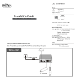
LED Indicators
LED
Color
Status
Definition
PWR1
PWR2
Green
On
Power is connected and active at
the PWR1/PWR2 input terminal
connection.
Off
PWR1/PWR2 is not connected.
ACT/ALM
Amber
On
When one or more of the
programmable alarm conditions is
active.
Green
On
During normal use, this LED will be
lit, indicating a healthy condition of
the running CPU.
Ring
Green
On
Lit when this unit is the 'master' in
a fiber ring and all units are
configured for u-Ring or ERPS
(Ethernet Ring Protection Switching
or G.8032).
Port 1~24
LAN
LINK/ACT
Green
On
The connected LAN speed is 10M
or 100M.
Blinking
Blinking when there is Ethernet
traffic.
Off
No Ethernet link.
Amber
On
The connected LAN speed is
1000M.
Blinking
Blinking when there is Ethernet
traffic.
Off
No Ethernet link.
Port
25~32
FIBER
LINK/ACT
Amber
On
The fiber link is up.
Blinking
Blinking when there is data traffic.
Off
No fiber link.
Port 1~24
PoE
Green
On
The respective LAN port has
successfully negotiated PoE and is
supplying output power to the
remote connected PD.
Off
PD is not connected or output
power is not provided.

16
Installation
The Gigabit Ethernet switch comes with rack-mounting hardware
brackets. When installing the rack-mounting brackets, be sure to
correctly align the orientation pin. Use the screws provided in the rack-
mounting kit to securely fasten the brackets.
Figure 9. Attaching Rack-Mounting Brackets
Figure 10. Core Switch with Rack-Mounting Brackets
Figure 11. Mounting Core Switch in Rack

17
Application
Figure 12. Network Application

18
Version
Date
Description
1.1
2020/9/25
Use new document format
/