
Basic
HITACHI SJ Series
Basic
Guide
HITACHI SJ Series
Guide
HITACHI SJ Series
I
nverter
Read this “Basic
nverter
Read this “Basic
P1
Read this “Basic
Guide
”, and keep it handy for future reference.
P1
”, and keep it handy for future reference.
If you have any
Refer to
or
C
ontact
for Inverter.
When making a contact, inform
the reference number on below.
Introduction
Contents
Chapter 1
:
Chapter 2
:
Chapter 4
:
Chapter 3
:
I/O Adjustment
Chapter 5
:
Chapter 6
:
Chapter 7
:
Index
”, and keep it handy for future reference.
If you have any
inquiry or problem
Refer to
Chapter 5 Troubleshooting
ontact
to
the Technical Inquiry Service
for Inverter.
List of contact information
When making a contact, inform
the reference number on below.
Introduction
NT
:
Safety Instructions
:
Installation and Wiring
Settings
:
Operation Setting and Examples of
I/O Adjustment
:
Troubleshooting
:
Maintenance and Inspection
:
Specifications
”, and keep it handy for future reference.
inquiry or problem
Chapter 5 Troubleshooting
the Technical Inquiry Service
List of contact information
When making a contact, inform
the reference number on below.
NT2511B
NT
2511
Safety Instructions
Installation and Wiring
Operation Setting and Examples of
Troubleshooting
Maintenance and Inspection
Specifications
”, and keep it handy for future reference.
inquiry or problem
,
Chapter 5 Troubleshooting
the Technical Inquiry Service
List of contact information
When making a contact, inform
the reference number on below.
NT2511B
X
Operation Setting and Examples of
Maintenance and Inspection
”, and keep it handy for future reference.
the Technical Inquiry Service

0-1
Introduction Introduction/Cautions
/Warranty & Contact us
Introduction
Thank you for purchasing Hitachi SJ Series P1 Inverter.
This is a user guide for basic handling and maintenance of
Hitachi SJ Series P1 Inverter.
For the purpose of reduction of paper usage and
provision of the latest information, we enclose the Basic
Guide only while providing the User's Guide for more
detailed description through electronic means instead of
CD or a printed document.
About the Basic Guide (this document)
The Basic Guide provides the minimum information
necessary for handling the product. Please make sure to
read this document as well as the User's Guide with more
detailed information.
About the User's Guide
The User's Guide provides detailed information necessary
for handling the product. Please make sure to read the
User's Guide for proper use.
If future updates make any difference from the Basic
Guide, the description in the User's Guide will have higher
priority. You should use the inverter by observing
specifications described in User's Guide. You should also
prevent risks by performing proper inspection and
maintenance.
Please refer to the following link for download:
Hitachi Industrial Equipment Systems' Website
http://www.hitachi-ies.co.jp/
Please follow as below on the Website.
Product Information -> Inverter -> Download of
technical data
Handling an optional products
If you use the inverter with optional products, also you
should read the instruction enclosed in those products.
Cautions
Proper use of the inverter
Please read the Basic Guide, User's Guide and optional
products instruction before handling. Read carefully the
Basic Guide, User's Guide or optional product instruction
before handling or performing maintenance of the
product.
Before attempting installation, operation, maintenance,
and inspection work, you should understand the
knowledge of equipment, information of safety,
precaution and how to use and service the inverter.
Cautions
No part of this document may be reproduced or reformed
in any form without the publisher's permission.
The contents of the document are subject to change
without prior notice.
If you lose the Basic Guide and need another one in
printed form, you will be charged for resupply, so please
keep it carefully.
You "CANNOT DO" what is not described in Basic Guide or
User's Guide. We are not responsible for any impact from
operations regardless of unexpected failure or accident
due to the operation or handling of the product in a
manner not specified in Basic Guide or User's Guide. We
apologize in advance for any inconvenience this may
cause.
If you find any unclear or incorrect description, missing
description, or misplaced or missing pages, please takes
time to inform Hitachi inverter technical service office.
Note that, the Basic Guide, User's Guide and the
instruction for each optional product enclosed, should be
delivered to the end user of the inverter. And also make
sure to be accessible any other guides or instruction to
the end user.

0-2
Introduction Introduction/Cautions
/Warranty & Contact us
Method of Inquiry and Product Warranty
Method of Inquiry about Product
• For an inquiry about product damage or faults or a question
about the product, notify your supplier or Hitachi inverter
technical service office.
Product Warranty
• The product SJ series P1 inverter will be warranted by Hitachi
Industrial Equipment Systems Co., Ltd., afterward "Hitachi",
during the warranty period from your date of purchase only
under proper usage of product.
• Furthermore, the warranty expressed here is covered only for
the product delivered from Hitachi, and will not be
responsible for others damage or loss of products like a
motor or any equipment or systems damage caused by
improper usage of the product. Minimize the consequence
on equipment or system by applying safety design which is
able to notify a hazard alarm to the user in case of
malfunction or damage of the delivered product. The
selection and application of delivered product must be done
with sufficient margin on performance, as well as other
equipment or system with sufficient redundancy design. Also,
the compatibility of the product with the customer's
intended use is not warranted, hence the validation test
should be done by the customer by their responsibility
before put in operation.
• In case of delivery a defective product, or encountered a
defects on quality during a manufacturing process, Hitachi
will repair or exchange with free of charge, only when the
product is in warranty period (afterward, we call "warranty
service").
• The product will be warranted for one year from your date of
purchase. However, depending on case, sending technical
assistance for repairing will be charged to the customer. Also,
Hitachi will not be responsible of any readjustment or testing
on site.
• After warranty service, the exchanged or repaired part will be
warranted for 6 month from date of warranty service. Hitachi
will be responsible for repair or exchange of defective part
only for the exchanged or repaired part only during this
warranty period.
• In order to receive warranty service, you should present the
recipe issued by product supplier or any other document that
permit to check the purchase date. However, any defects,
damage, malfunction or any other failure caused by one of
the following facts will not be covered by warranty service.
(1) Cannot confirm the purchase date.
(2) The damage or fault resulted from improper usage or
inadequate handling of the product and not conforming
usage described into the user's guide or basic guide.
(3) Incorrect usage of product, inadequate setting of
product and optional product, remodeling or inadequate
repair and repair carried out by unqualified repair
center.
(4) Deterioration and wear resulted from normal operation.
(5) Fault resulted from natural disaster, such as earthquake,
fire disaster, lightning strike, pollution, salt pollution, or
abnormal voltage or any others external factor.
(6) Shock, falling, or Vibration resulted during
transportation or displacement after purchase.
(7) Damage or fault resulted from remodeling firmware by
unqualified personal not belonging to Hitachi.
(8) Damage or fault resulted from customer's made
programing function (EzSQ).
(9) For overseas use.
• By warranty service, might lose the data stored inside the
product, as well as, customers made (EzSQ) program. Make
sure to back up by own responsibility. However, in case of
malfunction resulting from the circuit board of the storage
devices, the backup wil not be possible. It is recommended
to keep a backup during the testing phase by using VOP or PC
software ProDriveNext.
Liability Limitation
• Neither Hitachi-IES, Affiliated company nor related dealer are
liable to the written and unwritten public requirement
including the common sense of the product or requirement
in specific application
• Even more, Hitachi, affiliated company or related dealer are
not responsible of any incidental damage, special damage,
direct loss, or indirect loss (even predictable or not) resulted
on customer because of product defect.
■ Inverter Model: It beginning with P1- in specification label.
■ Manufacturer Number(MFG No.): It shows in specification label.
■ Date of purchase: Customer's purchased period.
■ Inquiry contents:
・ Inform us the defective point and its condition.
・ Inform us the suspicious content and its detail.

0-3
Introduction Introduction/Cautions
/Warranty & Contact us
Warranty Service
• The customer is able to receive a warranty service from
product supplier or service station, if the product does not
meet the function described on basic guide or user's guide.
Moreover, in case of any mismatch occurred between user's
guide and basic guide, user's guide content will take a
priority.
• Contact to your supplier or local Hitachi distributor or service
station for fare-paying services.
Change on Product Specification
• We are sorry because any information described in Brochure,
Basic Guide, User's Guide or Technical Document would be
modified without notice.
Precaution for Product Application
• The product should apply following the condition of use,
handling method and precautions described in User's Guide.
• The installed product should be confirmed previously by own
that the product installation has done as intended in the
customer system.
• When using Hitachi inverter consider on below
(1) Select inverter with sufficient capacity for rate current
and performance.
(2) Safety design, for example, redundant system design.
(3) Equipment design where minimize hazard in case of
inverter failure.
(4) For safety precautions, make a system configuration that
alarms the hazard to user.
(5) Periodic maintenance of Hitachi inverter and customer's
equipment.
• Hitachi inverter is designed and manufactured intentionally
to be applied for general industrial equipment application.
It is not intended to be used for the applications listed
below therefore. In case inverter is used for these
applications, it is out of warranty unless there is a special
written agreement. Otherwise, the product will not be
warranted.
(1) Special application such as aircraft, spacecraft, nuclear,
electric power, passenger transportation, medical,
submarine repeater, etc.
(2) For application such as elevator, amusement equipment,
medical equipment which might have a big effect on
human life and property.
• Even for above application, in case there is an agreement for
the limitation of the purpose and quality, please contact to
our sales office. Further study will be carried out to check
whether inverter is applicable for that specific application or
not.
• For applications that involve human life, or have risk of
important loss, make sure to avoid a critical accident by
installing a fail-safe device, protecting device, detecting
device, alarm device, or spare device, etc.
• This inverter is only for three phase induction motor [IM] or
three phase synchronous motor [SM(SMM)].
• For any other application make inquiries.
Supplement
• Refer to "Chapter 7 Specification" for short lifespan
component.
• For optional product refer attached instruction.
• This warranty term will not restrict a legal right of customer
who has purchased the product.
• Contact to the local supplier for warranty of purchased
product sales in oversea.
Contact Information
Hitachi America, Ltd. (Charlotte Office)
Industrial Components and Equipment Division
6901 Northpark Blvd., Suite A, Charlotte, NC 28216,
U.S.A
TEL : +1(704) 494-3008
FAX : +1(704) 599-4108
Hitachi Europe GmbH
Industrial Components & Equipment Group
Am Seestern 18 (Euro Center),
D-40547 Dusseldorf,
Germany
TEL : +49-211-5283-0
FAX : +49-211-5283-649
Hitachi Asia Ltd.
Industrial Components & Equipment Division
No.30 Pioneer Crescent, #10-15 West Park Bizcentral,
Singapore 628560,
Singapore
TEL : +65-6305-7400
FAX : +65-6305-7401
Hitachi Australia Ltd.
Level 3, 82 Waterloo Road
North Ryde, N.S.W.2113
Australia
TEL : +61-2-9888-4100
FAX : +61-2-9888-4188
Hitachi Industrial Equipment Systems Co., Ltd.
AKS Building, 3, Kanda
Nereibei-cho, Chiyoda-ku,
Tokyo, 101-0022
Japan
TEL : +81-3-4345-6910
FAX : +81-3-4345-6067

●
●
●
●
Contents
●
Quick start
●
Introduction/instructions
Types of Warnings
Description of Safety Symbols
Precautions for Installation
Precautions for Wiring
Precautions
Check the Inverter
Install the Inverter
Dimensions Drawing
Inverter Wiring
Wiring of
Recommended
Operation Setting and Examples of IO
Keypad
overview
Monitor
Troubleshooting
Cautions for Maintenance/Inspection
Daily and Periodic Inspections
Method of Checking the Inverter and Converter
Circuits
................................
Specifications Table
●
Appendix Index
●
Quick start
Chapter 1 Safety Instructions
Chapter 2 Installation and Wiring
Chapter 3 Operation Setting and Examples of IO Adjustment
Chapter 4 Settings
Chapter 5 Troubleshoot
Chapter 7 Specifications
Chapter 6
Contents
Quick start
................................
Introduction/instructions
Types of Warnings
................................
Description of Safety Symbols
Precautions for Installation
Precautions for Wiring
Precautions
to Run
and Test Running
Check the Inverter
................................
Install the Inverter
................................
Dimensions Drawing
................................
Inverter Wiring
................................
Wiring of
the main circuit
Recommended
wire gauges, accessories etc.
Operation Setting and Examples of IO
overview
................................
naming
................................
Troubleshooting
................................
Cautions for Maintenance/Inspection
Daily and Periodic Inspections
Method of Checking the Inverter and Converter
................................
Specifications Table
................................
Appendix Index
................................
Quick start
................................
Chapter 1 Safety Instructions
Chapter 2 Installation and Wiring
Chapter 3 Operation Setting and Examples of IO Adjustment
Chapter 4 Settings
Chapter 5 Troubleshoot
Chapter 7 Specifications
Chapter 6
Inspection and
................................
..............................
Introduction/instructions
................................
................................
Description of Safety Symbols
..............................
Precautions for Installation
................................
Precautions for Wiring
................................
and Test Running
................................
................................
................................
................................
the main circuit
................................
wire gauges, accessories etc.
Operation Setting and Examples of IO
................................
................................
................................
Cautions for Maintenance/Inspection
Daily and Periodic Inspections
..............................
Method of Checking the Inverter and Converter
................................
................................
................................
................................
................................
.................
Chapter 1 Safety Instructions
Chapter 2 Installation and Wiring
Chapter 3 Operation Setting and Examples of IO Adjustment
Chapter 5 Troubleshoot
ing
Chapter 7 Specifications
Inspection and
Maintenance
..............................
................................
.......
................................
................
..............................
................................
.
................................
........
and Test Running
.................
................................
................
................................
................
................................
.............
................................
.....................
................................
.....
wire gauges, accessories etc.
.......
Operation Setting and Examples of IO
Adjustment
................................
..................
................................
..................
4
................................
....................
Cautions for Maintenance/Inspection
..................
..............................
Method of Checking the Inverter and Converter
................................
..
................................
..............
................................
...........
index
.................
Appendix
Chapter 2 Installation and Wiring
Chapter 3 Operation Setting and Examples of IO Adjustment
Maintenance
0-4
..............................
0-1
.......
0-2
................
1-1
..............................
1-1
.
1-2
........
1-2
.................
1-3
................
2-1
................
2-2
.............
2-4
.....................
2-6
.....
2-7
.......
2-8
Adjustment
3-1
..................
4-1
4
-10
....................
5-1
..................
6-1
..............................
6-2
..
6-4
..............
7-1
index
-1
Appendix
-1
●
●
Precautions
Precautions for
Other Cautions
Compliance
Compliance
Applicable Circuit Breaker
Ch
opper Breaking Resistor
Wiring
Wiring of the Control Circuit
Control Circuit Wiring Section
Residual Risk
Parameters
DC
-
Output of Life Warning
Methods of Measuring the Input/Output Voltages,
Current, and Power
Chapter 3 Operation Setting and Examples of IO Adjustment
Method of Inquiry and Product Warranty
Contents
................................
Precautions
for Maintenance/Inspection
Precautions for
Dispolsal
Other Cautions
................................
Compliance
to European Directive (CE)
Compliance
to UL standards
Applicable Circuit Breaker
opper Breaking Resistor
Wiring
................................
Wiring of the Control Circuit
Control Circuit Wiring Section
Residual Risk
................................
Parameters
naming
-
Bus Capacitor Life
Output of Life Warning
Methods of Measuring the Input/Output Voltages,
Current, and Power
Chapter 3 Operation Setting and Examples of IO Adjustment
Method of Inquiry and Product Warranty
................................
for Maintenance/Inspection
Dispolsal
................................
................................
to European Directive (CE)
to UL standards
................................
Applicable Circuit Breaker
................................
opper Breaking Resistor
................................
................................
................................
Wiring of the Control Circuit
................................
Control Circuit Wiring Section
................................
................................
naming
................................
Bus Capacitor Life
Curve
................................
Output of Life Warning
................................
Methods of Measuring the Input/Output Voltages,
Current, and Power
................................
Method of Inquiry and Product Warranty
................................
...............................
for Maintenance/Inspection
.................
................................
................................
............................
to European Directive (CE)
......................
................................
................................
................................
................................
................................
................................
................................
.............................
................................
...................
................................
................................
Methods of Measuring the Input/Output Voltages,
................................
.....................
Contents
Method of Inquiry and Product Warranty
.......... 0-3
...............................
0-4
.................
1-4
................................
.......... 1-4
............................
1-4
......................
1-5
................................
....... 1-7
................................
......... 2-10
................................
........ 2-12
................................
....... 2-13
................................
..... 2-17
................................
... 2-19
.............................
2-24
...................
4-13
................................
........ 6-5
................................
............... 6-5
Methods of Measuring the Input/Output Voltages,
.....................
6-6

0-5
Contents
Contents
(Memo)

Chapter 1
1.1
In the Basic Manual, the severity levels of
precautions and residual risks are classified as:
"
Display
Even more, that "
to a serious risk depend on the circumstances. Be sure to
follow the instruction because whichever contains
important safety description.
Chapter 1
Chapter 1
Safety Instructions
1.1
Types of Warnings
In the Basic Manual, the severity levels of
precautions and residual risks are classified as:
"
WARNING"
and
Display
m
eanings
Indicates that incorrect handling may cause hazardous
situations, which would most likely result in serious
personal
injury or death,
loss or damage.
Indicates that incorrect
situations, which may result in serious personal injury or
death, and may result in major
Indicates that incorrect handling may cause hazardous
situations,
which may result in moderate or slig
personal
injury or damage, and may result
loss or damage.
Even more, that "
to a serious risk depend on the circumstances. Be sure to
follow the instruction because whichever contains
important safety description.
Chapter 1
Chapter 1
Safety Instructions
Types of Warnings
In the Basic Manual, the severity levels of
precautions and residual risks are classified as:
and
"
CAUTION
eanings
Indicates that incorrect handling may cause hazardous
situations, which would most likely result in serious
injury or death,
and may result in major physical
loss or damage.
WARNING
Indicates that incorrect
handling may cause hazardous
situations, which may result in serious personal injury or
death, and may result in major
CAUTION
Indicates that incorrect handling may cause hazardous
which may result in moderate or slig
injury or damage, and may result
loss or damage.
Even more, that "
CAUTION
to a serious risk depend on the circumstances. Be sure to
follow the instruction because whichever contains
important safety description.
Safety Instructions
Types of Warnings
In the Basic Manual, the severity levels of
precautions and residual risks are classified as:
CAUTION
".
DANGER
Indicates that incorrect handling may cause hazardous
situations, which would most likely result in serious
and may result in major physical
WARNING
handling may cause hazardous
situations, which may result in serious personal injury or
death, and may result in major
physical loss or damage.
CAUTION
Indicates that incorrect handling may cause hazardous
which may result in moderate or slig
injury or damage, and may result
CAUTION
" level description may lead
to a serious risk depend on the circumstances. Be sure to
follow the instruction because whichever contains
important safety description.
In the Basic Manual, the severity levels of
safety
precautions and residual risks are classified as:
"
DANGER
DANGER
Indicates that incorrect handling may cause hazardous
situations, which would most likely result in serious
and may result in major physical
WARNING
handling may cause hazardous
situations, which may result in serious personal injury or
physical loss or damage.
CAUTION
Indicates that incorrect handling may cause hazardous
which may result in moderate or slig
ht
injury or damage, and may result
only
physical
" level description may lead
to a serious risk depend on the circumstances. Be sure to
follow the instruction because whichever contains
1-1
DANGER
",
Indicates that incorrect handling may cause hazardous
and may result in major physical
handling may cause hazardous
situations, which may result in serious personal injury or
physical loss or damage.
Indicates that incorrect handling may cause hazardous
physical
" level description may lead
to a serious risk depend on the circumstances. Be sure to
1.2
It describes annotation of t
to follow and pay attention of content.
Symbols
1.3 Description of Safety Symbols
Read carefully following safety instruction for handling.
1.2
Description of Safety Symbols
It describes annotation of t
to follow and pay attention of content.
Symbols
m
eaning
Indicates a danger, warning or caution notice
for
fire, electric shock and high temperature
while handling the product
Details are indicated in or near
or words.
Indicates “what you must not do”
the described acts
product.
Indicates “what you must do”
the instructions
product.
1.3 Description of Safety Symbols
Read carefully following safety instruction for handling.
Safety Instructions
Description of Safety Symbols
It describes annotation of t
he
s
to follow and pay attention of content.
eaning
Indicates a danger, warning or caution notice
fire, electric shock and high temperature
while handling the product
Details are indicated in or near
or words.
The
drawing on the left indicates
non-
specific and general
caution”.
The drawing on the left indicates
possible
damage
shock”.
Indicates “what you must not do”
the described acts
product.
Indicates “what you must do”
the instructions
in the operation of the
product.
1.3 Description of Safety Symbols
Read carefully following safety instruction for handling.
Safety Instructions
Description of Safety Symbols
he
s
ymbols in context
to follow and pay attention of content.
Indicates a danger, warning or caution notice
fire, electric shock and high temperature
while handling the product
.
Details are indicated in or near
drawing on the left indicates
specific and general
The drawing on the left indicates
damage
due to electric
Indicates “what you must not do”
the described acts
in the
operation of the
Indicates “what you must do”
according to
in the operation of the
1.3 Description of Safety Symbols
Read carefully following safety instruction for handling.
Safety Instructions
Description of Safety Symbols
ymbols in context
. Be sure
Indicates a danger, warning or caution notice
fire, electric shock and high temperature
by pictures
drawing on the left indicates
“a
specific and general
danger or
The drawing on the left indicates
“a
due to electric
Indicates “what you must not do”
to prohibit
operation of the
according to
in the operation of the
1.3 Description of Safety Symbols
Read carefully following safety instruction for handling.
Safety Instructions
. Be sure
Indicates a danger, warning or caution notice
“a
“a
to prohibit

Chapter 1
1.3.1
Caution
•
•
1.3.2
Precautions for installation
●
•
•
•
•
●
•
1.3.3 P
recautions for Wiring
●
•
•
•
●
•
Caution
Practice
Fire
Injury
Prohibited
Electric
shock Fire
Practice
Failure
Prohibited
Practice
Prohibited
Chapter 1
Caution
Incorrect handling may result in personal
or severe injury, or may result in damage to
inverter, motor or the whole system.
Be sure to read this Basic Manual and
documents thoroughly
operating, maintaining, inspecting or
inverter.
Precautions for installation
You run the risk of fire!
Do not place flammable materials near
installed inverter.
Prevent foreign matter (e.g., cut pieces of wire,
sputtering welding materials, iron chips, wire,
and dust) from
Install the inverter on a non
such as, metal
Install the inverter in a well
site
not exposed to direct sunlight.
where the inverter is exposed to high
temperature,
high humidity, condensation, dust,
explosive gases,
gases, g
rinding fluid mist,
●
You run the risk of injury!
Do not install and operate the inverter
damaged or its parts are missing.
recautions for Wiring
●
You run the risk of electric shock or
fire!
Be sure to ground
Commit wiring work to
Before wiring, make sure that the power supply
is off.
●
You
run the risk of failure of the
inverter!
Do not pull the wire after wiring.
Incorrect handling may result in personal
or severe injury, or may result in damage to
inverter, motor or the whole system.
Be sure to read this Basic Manual and
documents thoroughly
before installing, wiring,
operating, maintaining, inspecting or
Precautions for installation
You run the risk of fire!
Do not place flammable materials near
installed inverter.
Prevent foreign matter (e.g., cut pieces of wire,
sputtering welding materials, iron chips, wire,
and dust) from
penetrating into
Install the inverter on a non
-
surface.
Install the inverter in a well
not exposed to direct sunlight.
where the inverter is exposed to high
high humidity, condensation, dust,
explosive gases,
corrosive gases, flammable
rinding fluid mist,
or salt water.
You run the risk of injury!
Do not install and operate the inverter
damaged or its parts are missing.
recautions for Wiring
You run the risk of electric shock or
Be sure to ground
the inverter.
Commit wiring work to
a qualified electrician.
Before wiring, make sure that the power supply
run the risk of failure of the
Do not pull the wire after wiring.
Incorrect handling may result in personal
death
or severe injury, or may result in damage to
inverter, motor or the whole system.
Be sure to read this Basic Manual and
appended
before installing, wiring,
operating, maintaining, inspecting or
using the
Do not place flammable materials near
to
Prevent foreign matter (e.g., cut pieces of wire,
sputtering welding materials, iron chips, wire,
penetrating into
the inverter.
-
flammable surface,
Install the inverter in a well
-
ventilated indoor
not exposed to direct sunlight.
Avoid places
where the inverter is exposed to high
high humidity, condensation, dust,
corrosive gases, flammable
or salt water.
You run the risk of injury!
Do not install and operate the inverter
if it is
damaged or its parts are missing.
You run the risk of electric shock or
the inverter.
a qualified electrician.
Before wiring, make sure that the power supply
run the risk of failure of the
Do not pull the wire after wiring.
WARNING
D
DANGER
1-2
death
or severe injury, or may result in damage to
the
appended
before installing, wiring,
using the
to
the
Prevent foreign matter (e.g., cut pieces of wire,
sputtering welding materials, iron chips, wire,
the inverter.
flammable surface,
ventilated indoor
Avoid places
where the inverter is exposed to high
high humidity, condensation, dust,
corrosive gases, flammable
if it is
a qualified electrician.
Before wiring, make sure that the power supply
Failure
Prohibited
WARNING
D
AN
GER
DANGER
Caution
Fall
Injury
Prohibited
Practice
Electric
shock
Injury
Short
circuit
Ground
fault
Prohibited
Practice
Practice
•
Many of the drawings
inverter with covers and/or parts
as removed to
•
Do not operate the inverter in the status shown in
those drawings. If you have removed the
and/or parts, be sure to reinstall them in their
original positions before starting operation,
follow all instructions when operating the inverter.
●
You run the risk of injury due to the
inverter falling
•
Do not hold its cover parts w
inverter.
•
Install the inverter on a structure able to bear
the weight specified in this Basic
•
Install the inverter on a vertical wall that is free
of vibrations.
●
You run the risk of failure of the inverter!
•
The inverter is precision equipment.
allow it to fall or be subject to high impacts.
•
Also do not step on it, or place a heavy load on
it.
●
You run the risk of electric shock and
injury!
•
Perform wiring
●
You run the risk of short circuit and ground
fault!
•
Do not remove rubber bushings from the wiring
section.
may damage the wire.
Failure
Prohibited
WARNING
GER
DANGER
Caution
Fall
Injury
Prohibited
Practice
Electric
shock
Injury
Short
circuit
Ground
fault
Prohibited
Practice
Practice
Safety Instructions
Many of the drawings
inverter with covers and/or parts
as removed to
illustrate the details.
Do not operate the inverter in the status shown in
those drawings. If you have removed the
and/or parts, be sure to reinstall them in their
original positions before starting operation,
follow all instructions when operating the inverter.
You run the risk of injury due to the
inverter falling
Do not hold its cover parts w
inverter.
Install the inverter on a structure able to bear
the weight specified in this Basic
Install the inverter on a vertical wall that is free
of vibrations.
You run the risk of failure of the inverter!
The inverter is precision equipment.
allow it to fall or be subject to high impacts.
Also do not step on it, or place a heavy load on
You run the risk of electric shock and
injury!
Perform wiring
only after installing the inverter.
You run the risk of short circuit and ground
fault!
Do not remove rubber bushings from the wiring
section.
Otherwise, the edges of the wiring cover
may damage the wire.
Safety Instructions
Many of the drawings
in the Basic
inverter with covers and/or parts
blocking your view
illustrate the details.
Do not operate the inverter in the status shown in
those drawings. If you have removed the
and/or parts, be sure to reinstall them in their
original positions before starting operation,
follow all instructions when operating the inverter.
You run the risk of injury due to the
Do not hold its cover parts w
hen carrying the
Install the inverter on a structure able to bear
the weight specified in this Basic
Install the inverter on a vertical wall that is free
You run the risk of failure of the inverter!
The inverter is precision equipment.
allow it to fall or be subject to high impacts.
Also do not step on it, or place a heavy load on
You run the risk of electric shock and
only after installing the inverter.
You run the risk of short circuit and ground
Do not remove rubber bushings from the wiring
Otherwise, the edges of the wiring cover
may damage the wire.
Safety Instructions
in the Basic
Guide show
the
blocking your view
Do not operate the inverter in the status shown in
those drawings. If you have removed the
covers
and/or parts, be sure to reinstall them in their
original positions before starting operation,
and
follow all instructions when operating the inverter.
You run the risk of injury due to the
hen carrying the
Install the inverter on a structure able to bear
the weight specified in this Basic
Guide.
Install the inverter on a vertical wall that is free
You run the risk of failure of the inverter!
The inverter is precision equipment.
Do not
allow it to fall or be subject to high impacts.
Also do not step on it, or place a heavy load on
You run the risk of electric shock and
only after installing the inverter.
You run the risk of short circuit and ground
Do not remove rubber bushings from the wiring
Otherwise, the edges of the wiring cover
Safety Instructions
the
blocking your view
Do not operate the inverter in the status shown in
covers
and/or parts, be sure to reinstall them in their
and
hen carrying the
Install the inverter on a structure able to bear
Install the inverter on a vertical wall that is free
Do not
Also do not step on it, or place a heavy load on
only after installing the inverter.
Do not remove rubber bushings from the wiring
Otherwise, the edges of the wiring cover

Chapter 1
●
●
1.3.4 P
recautions
●
●
●
Injury
Fire
Practice
Electric
shock
Injury
Prohibited
Electric
shock
Fire
Prohibited
Prohibited
Electric
shock
Prohibited
Injury
Fire
Practice
Chapter 1
●
You run the risk of injury or fire!
•
Do not connect AC power supply to
output terminals (U, V, and W)
•
Make sure that the voltage of AC power supply
matches the rated voltage of your inverter.
●
You run the risk of electric shock
and injury!
•
Before operating slide switch SW in the
inverter, be sure to turn off the power supply.
•
Since the inverter supports two modes of
cooling-
fan operation, the inverter power is
not always off, even when the cooling fan is
stopped.
Therefore, be su
the power supply is off before wiring.
recautions
to
Run and
●
You run the risk of electric shock or
fire!
•
While power is supplied to the
touch any internal part or terminal of the
inverter. Also do not check signals, or connect
or disconnect any wire or connector.
•
While power is supplied to the inverter, do not
touch any internal part of the in
not insert a
m
●
You run the risk of electric shock!
•
Be sure to close the terminal block cover
before turning on the inverter power.
open the terminal block cover
being supplied to the inverter or
remains inside.
•
Do not operate switches
●
You run the risk of injury or fire!
•
While power is supplied to the inverter,
touch the
terminal of the inverter,
has stopped.
You run the risk of injury or fire!
Do not connect AC power supply to
output terminals (U, V, and W)
Make sure that the voltage of AC power supply
matches the rated voltage of your inverter.
You run the risk of electric shock
and injury!
Before operating slide switch SW in the
inverter, be sure to turn off the power supply.
Since the inverter supports two modes of
fan operation, the inverter power is
not always off, even when the cooling fan is
Therefore, be su
the power supply is off before wiring.
Run and
Test Running
You run the risk of electric shock or
While power is supplied to the
touch any internal part or terminal of the
inverter. Also do not check signals, or connect
or disconnect any wire or connector.
While power is supplied to the inverter, do not
touch any internal part of the in
m
aterial such as a rod
You run the risk of electric shock!
Be sure to close the terminal block cover
before turning on the inverter power.
open the terminal block cover
being supplied to the inverter or
remains inside.
Do not operate switches
with wet hands.
You run the risk of injury or fire!
While power is supplied to the inverter,
terminal of the inverter,
has stopped.
You run the risk of injury or fire!
Do not connect AC power supply to
any of the
output terminals (U, V, and W)
.
Make sure that the voltage of AC power supply
matches the rated voltage of your inverter.
You run the risk of electric shock
Before operating slide switch SW in the
inverter, be sure to turn off the power supply.
Since the inverter supports two modes of
fan operation, the inverter power is
not always off, even when the cooling fan is
Therefore, be su
re to confirm that
the power supply is off before wiring.
Test Running
You run the risk of electric shock or
While power is supplied to the
inverter, do not
touch any internal part or terminal of the
inverter. Also do not check signals, or connect
or disconnect any wire or connector.
While power is supplied to the inverter, do not
touch any internal part of the in
verter. Also do
aterial such as a rod
and etc.
You run the risk of electric shock!
Be sure to close the terminal block cover
before turning on the inverter power.
Do not
open the terminal block cover
while power is
being supplied to the inverter or
voltage
with wet hands.
You run the risk of injury or fire!
While power is supplied to the inverter,
do not
terminal of the inverter,
even if it
WARNING
DANGER
1-3
any of the
Make sure that the voltage of AC power supply
matches the rated voltage of your inverter.
Before operating slide switch SW in the
inverter, be sure to turn off the power supply.
Since the inverter supports two modes of
fan operation, the inverter power is
not always off, even when the cooling fan is
re to confirm that
inverter, do not
touch any internal part or terminal of the
inverter. Also do not check signals, or connect
While power is supplied to the inverter, do not
verter. Also do
and etc.
.
Be sure to close the terminal block cover
Do not
while power is
voltage
do not
even if it
WARNING
Prohibited
Injury
Damage
Prohibited
Injury
Prohibited
Practice
Practice
DANGER
●
•
Do not use a single
•
Do not connect a resistor directly to any of the
DC terminals (PD, P, and N).
•
Do not use
the primary and secondary sides of the inverter
to stop its operation.
•
Tighten each screw to the specified torque.
•
No screws must be left loose.
•
Connect an earth
input circuit.
•
Use only the power cables, earth
breaker, and magnetic contactors that have
specified capacity (ratings).
●
• Do
not select the retry mode for controlling an
elevating or traveling device because free
status occurs in retry mode.
●
•
If the retry mode has been selected, the inverter
will restart suddenly after a break in the tripping
status.
the inverter when the inverter is under such
circumstances.
safety can be ensured,
restarts sudden
•
The [STOP] key on the operator keypad is effective
only when its function is enabled by setting.
Prepare an emergency
•
If an operation command has been input to
inverter
inverter may
recovery.
danger,
inverter
•
If an operation command has been input to the
inverter before the inverter enters alarm status,
the inverter will restart suddenly when the alarm
status is reset.
make sure that no operation command
input.
WARNING
Fire
Prohibited
Injury
Damage
Prohibited
Injury
Prohibited
Practice
Practice
DANGER
Safety Instructions
You run the risk of fire!
Do not use a single
Do not connect a resistor directly to any of the
DC terminals (PD, P, and N).
Do not use
the magnetic contactor installed on
the primary and secondary sides of the inverter
to stop its operation.
Tighten each screw to the specified torque.
No screws must be left loose.
Connect an earth
-
input circuit.
Use only the power cables, earth
breaker, and magnetic contactors that have
specified capacity (ratings).
You run the risk of injury and damage to
machine.
not select the retry mode for controlling an
elevating or traveling device because free
status occurs in retry mode.
You run the risk of injury!
If the retry mode has been selected, the inverter
will restart suddenly after a break in the tripping
status.
Stay away from the machine controlled by
the inverter when the inverter is under such
circumstances.
(Design the machine so that human
safety can be ensured,
restarts sudden
ly.)
The [STOP] key on the operator keypad is effective
only when its function is enabled by setting.
Prepare an emergency
If an operation command has been input to
inverter
before a short
inverter may
restart operation after the power
recovery.
If such a restart may put persons in
danger,
design a control circuit that disables the
inverter
rom restarting after power recovery.
If an operation command has been input to the
inverter before the inverter enters alarm status,
the inverter will restart suddenly when the alarm
status is reset.
Before resetting the alarm status,
make sure that no operation command
input.
Safety Instructions
You run the risk of fire!
Do not use a single
-phase input.
Do not connect a resistor directly to any of the
DC terminals (PD, P, and N).
the magnetic contactor installed on
the primary and secondary sides of the inverter
to stop its operation.
Tighten each screw to the specified torque.
No screws must be left loose.
Connect an earth
-
leakage breaker
Use only the power cables, earth
breaker, and magnetic contactors that have
specified capacity (ratings).
You run the risk of injury and damage to
not select the retry mode for controlling an
elevating or traveling device because free
status occurs in retry mode.
You run the risk of injury!
If the retry mode has been selected, the inverter
will restart suddenly after a break in the tripping
Stay away from the machine controlled by
the inverter when the inverter is under such
(Design the machine so that human
safety can be ensured,
even when the inverter
The [STOP] key on the operator keypad is effective
only when its function is enabled by setting.
Prepare an emergency
stop switch separately.
If an operation command has been input to
before a short
-term
power failure, the
restart operation after the power
If such a restart may put persons in
design a control circuit that disables the
rom restarting after power recovery.
If an operation command has been input to the
inverter before the inverter enters alarm status,
the inverter will restart suddenly when the alarm
Before resetting the alarm status,
make sure that no operation command
Safety Instructions
Do not connect a resistor directly to any of the
the magnetic contactor installed on
the primary and secondary sides of the inverter
Tighten each screw to the specified torque.
leakage breaker
to the po
wer
Use only the power cables, earth
-
leakage
breaker, and magnetic contactors that have
the
You run the risk of injury and damage to
not select the retry mode for controlling an
elevating or traveling device because free
-
running
If the retry mode has been selected, the inverter
will restart suddenly after a break in the tripping
Stay away from the machine controlled by
the inverter when the inverter is under such
(Design the machine so that human
even when the inverter
The [STOP] key on the operator keypad is effective
only when its function is enabled by setting.
stop switch separately.
If an operation command has been input to
the
power failure, the
restart operation after the power
If such a restart may put persons in
design a control circuit that disables the
rom restarting after power recovery.
If an operation command has been input to the
inverter before the inverter enters alarm status,
the inverter will restart suddenly when the alarm
Before resetting the alarm status,
make sure that no operation command
has been
Safety Instructions
Do not connect a resistor directly to any of the
the magnetic contactor installed on
the primary and secondary sides of the inverter
wer
leakage
the
You run the risk of injury and damage to
not select the retry mode for controlling an
running
If the retry mode has been selected, the inverter
will restart suddenly after a break in the tripping
Stay away from the machine controlled by
the inverter when the inverter is under such
(Design the machine so that human
even when the inverter
The [STOP] key on the operator keypad is effective
only when its function is enabled by setting.
the
power failure, the
restart operation after the power
If such a restart may put persons in
design a control circuit that disables the
If an operation command has been input to the
inverter before the inverter enters alarm status,
the inverter will restart suddenly when the alarm
Before resetting the alarm status,
has been

Chapter 1
●
1.3.5
Precautions for
●
1.3.6
Precautions for disposal
●
1.3.7 O
ther Cautions
●
•
Injury
Damage
Practice
Electric
shock
Practice
Electric
shock
Fire
Injury
Prohibited
Injury
Explosion
Practice
Chapter 1
●
You run the
machine.
•
The inverter
speed
of
operating
capacity and ratings
before operating
•
When you run the motor at a high frequency,
check
and confirm to each manufactures of a
permitting revolution of
and machine
• Check the
rotate
sound,
and vibrations
Precautions for
Maintenance/Inspection
●
You run the risk of electric shock!
•
Before inspecting the inverter, be sure to turn
off the power supply and
or more.
(Before inspection, confirm
Charge lamp
voltage between terminals P and N is
less.)
Precautions for disposal
●
You run the risk of injury and
explosion!
•
For disposal of the inverter, outsource to a
qualified
industrial waste disposal contractor.
Disposing of the inverter on your own may
result in an explosion of the capacitor or
produce poisonous gas.
•
Contact us or your distributor
inverter.
ther Cautions
●
You run the risk of electric shock, fire
and injury!
•
Never modify the inverter.
DANGER
You run the
risk of injury and damage to
The inverter
easily
allows you to
operating
motor.
capacity and ratings
of the motor or machine
before operating
.
When you run the motor at a high frequency,
and confirm to each manufactures of a
permitting revolution of
the
and machine
.
rotate
motor
direction
and vibrations
while operating
Maintenance/Inspection
You run the risk of electric shock!
Before inspecting the inverter, be sure to turn
off the power supply and
wait for 10 minutes
(Before inspection, confirm
Charge lamp
on the inverter is off and
voltage between terminals P and N is
Precautions for disposal
You run the risk of injury and
explosion!
For disposal of the inverter, outsource to a
industrial waste disposal contractor.
Disposing of the inverter on your own may
result in an explosion of the capacitor or
produce poisonous gas.
Contact us or your distributor
You run the risk of electric shock, fire
and injury!
Never modify the inverter.
DANGER
risk of injury and damage to
allows you to
c
ontrol the
motor.
C
onfirm the
of the motor or machine
When you run the motor at a high frequency,
and confirm to each manufactures of a
the
respective
motor
direction
, abnormal
while operating
.
Maintenance/Inspection
You run the risk of electric shock!
Before inspecting the inverter, be sure to turn
wait for 10 minutes
(Before inspection, confirm
that the
on the inverter is off and
the DC
voltage between terminals P and N is
45 V or
You run the risk of injury and
For disposal of the inverter, outsource to a
industrial waste disposal contractor.
Disposing of the inverter on your own may
result in an explosion of the capacitor or
Contact us or your distributor
for fixing the
You run the risk of electric shock, fire
Never modify the inverter.
WARNING
DANGER
DANGER
1-4
risk of injury and damage to
ontrol the
onfirm the
of the motor or machine
When you run the motor at a high frequency,
and confirm to each manufactures of a
motor
, abnormal
Maintenance/Inspection
Before inspecting the inverter, be sure to turn
wait for 10 minutes
that the
the DC
45 V or
For disposal of the inverter, outsource to a
industrial waste disposal contractor.
Disposing of the inverter on your own may
result in an explosion of the capacitor or
for fixing the
You run the risk of electric shock, fire
WARNING
Burn
I
njury
Prohibited
Injury
Practice
DANGER
Prohibited
DANGER
Practice
Life cycle
Practice
●
You run the risk of burn injury.
•
Inverter heat sink will heat up during operation.
Do not touch the heat sink
●
You run the risk of injury!
•
Install an external brake system
•
Commit only a designated person to
maintenance,
of parts.
metal accessories, e.g., bracelets,
maintenance and inspection work and to use
insulated tools
•
A qualified waste disposer includes
industr
ind
the
the
c
leansing
●
You run the risk of
the
•
Sterilizing and disinfecting a packaging
materials
fumigation method.
the fumigation treatment,
receive a critical damage
steams
(including fluorine, chlorine, bromine and
iodine)
WARNING
Burn
njury
Prohibited
Injury
Practice
DANGER
Prohibited
DANGER
Practice
Life cycle
Practice
Safety Instructions
You run the risk of burn injury.
Inverter heat sink will heat up during operation.
Do not touch the heat sink
You run the risk of injury!
Install an external brake system
Commit only a designated person to
maintenance,
inspection, and the replacement
of parts.
(Be sure to remove wristwatches and
metal accessories, e.g., bracelets,
maintenance and inspection work and to use
insulated tools
for the
A qualified waste disposer includes
industr
ial waste collector/transporter
ind
ustrial waste disposal operator
the
act related to
the
waste
m
leansing
for
disposing of the inverter.
You run the risk of
the
life cycle of
a
Sterilizing and disinfecting a packaging
materials
use a means other than
fumigation method.
the fumigation treatment,
receive a critical damage
steams
.
Especially,
(including fluorine, chlorine, bromine and
iodine)
can cause corrosion in
CAUTION
Safety Instructions
You run the risk of burn injury.
Inverter heat sink will heat up during operation.
Do not touch the heat sink
.
You run the risk of injury!
Install an external brake system
if needed.
Commit only a designated person to
inspection, and the replacement
(Be sure to remove wristwatches and
metal accessories, e.g., bracelets,
maintenance and inspection work and to use
for the
work.)
A qualified waste disposer includes
ial waste collector/transporter
ustrial waste disposal operator
act related to
procedures stipulated in
m
anagement and
disposing of the inverter.
You run the risk of
significantly
a
product!
Sterilizing and disinfecting a packaging
use a means other than
fumigation method.
If the product is included in
the fumigation treatment,
electronic parts
receive a critical damage
from emitted gases or
Especially,
halogen disinfectants
(including fluorine, chlorine, bromine and
can cause corrosion in
the capacitor.
CAUTION
Safety Instructions
You run the risk of burn injury.
Inverter heat sink will heat up during operation.
if needed.
Commit only a designated person to
inspection, and the replacement
(Be sure to remove wristwatches and
metal accessories, e.g., bracelets,
before
maintenance and inspection work and to use
A qualified waste disposer includes
ial waste collector/transporter
and
ustrial waste disposal operator
. Follow
procedures stipulated in
anagement and
p
ublic
disposing of the inverter.
significantly
shortening
Sterilizing and disinfecting a packaging
wood
use a means other than
wood
If the product is included in
electronic parts
from emitted gases or
halogen disinfectants
(including fluorine, chlorine, bromine and
the capacitor.
Safety Instructions
Inverter heat sink will heat up during operation.
Commit only a designated person to
inspection, and the replacement
(Be sure to remove wristwatches and
before
maintenance and inspection work and to use
A qualified waste disposer includes
and
. Follow
procedures stipulated in
ublic
shortening
wood
wood
If the product is included in
electronic parts
from emitted gases or
halogen disinfectants
(including fluorine, chlorine, bromine and

1.4
(CE)
Compatibility)
The SJ series P1 inverter conforms to requirements of
Electromagnetic Compatibility (EMC) Directive (2014/30/EU).
However, when using the
with the following specifications and requirements to meet the
EMC Directive and other standards in Europe:
1. Power supply requirements
2. Installation requirement
3. Wiring requirements
4. Environmental requirements
Chapter 1
1.4
Compliance
(CE)
1.4.1
Caution for EMC (Electromagnetic
Compatibility)
The SJ series P1 inverter conforms to requirements of
Electromagnetic Compatibility (EMC) Directive (2014/30/EU).
However, when using the
with the following specifications and requirements to meet the
EMC Directive and other standards in Europe:
WARNING: This equipment must be installed, adjusted,
and maintained by qualified engineers who have expert
kno
wledge of electric work, inverter operation, and the
hazardous circumstances that can occur. Otherwise,
personal injury may result.
1. Power supply requirements
a. Voltage fluctuation must be
b. Voltage imbalance must be ±3% or less.
c. Frequency variation must be ±4% or less.
d. Total harmonic distortion (THD) of voltage must be ±10% or
less.
2. Installation requirement
a. SJ series P1 includes a built
filter must be activated.
b.
According to EN61800
any inverter with only C3 filter inside may NOT be
connected to a low voltage public power supply in
residential areas since for these installations C1 is required.
c.
In case of external filter
required according to EN61800
emit
high frequency interference in residential areas which
may require additional EMC measures”.
d. According to the EN6100
DC choke should
power line.
3. Wiring requirements
a. A shielded wire (screened cable) must be used for motor
wiring, and the length of the cable must be according to the
following table (Table 1 on page 1
b. The carrier frequ
following table to meet an EMC requirement (Table1 on
page 1-12).
c. The main circuit wiring must be separated from the control
circuit wiring.
4. Environmental requirements
(When an
EMC
a. SJ series P1
must be according to SJ series P1 specifications.
Chapter 1
Compliance
to European Directive
Caution for EMC (Electromagnetic
Compatibility)
The SJ series P1 inverter conforms to requirements of
Electromagnetic Compatibility (EMC) Directive (2014/30/EU).
However, when using the
inverter in Europe, you must comply
with the following specifications and requirements to meet the
EMC Directive and other standards in Europe:
WARNING: This equipment must be installed, adjusted,
and maintained by qualified engineers who have expert
wledge of electric work, inverter operation, and the
hazardous circumstances that can occur. Otherwise,
personal injury may result.
1. Power supply requirements
a. Voltage fluctuation must be
b. Voltage imbalance must be ±3% or less.
c. Frequency variation must be ±4% or less.
d. Total harmonic distortion (THD) of voltage must be ±10% or
2. Installation requirement
a. SJ series P1 includes a built
filter must be activated.
According to EN61800
-
3 it is mandatory to mention that
any inverter with only C3 filter inside may NOT be
connected to a low voltage public power supply in
residential areas since for these installations C1 is required.
In case of external filter
for
required according to EN61800
high frequency interference in residential areas which
may require additional EMC measures”.
d. According to the EN6100
-
3
DC choke should
be installed
3. Wiring requirements
a. A shielded wire (screened cable) must be used for motor
wiring, and the length of the cable must be according to the
following table (Table 1 on page 1
b. The carrier frequ
ency must be set according to the
following table to meet an EMC requirement (Table1 on
c. The main circuit wiring must be separated from the control
circuit wiring.
4. Environmental requirements
EMC
filter is used)
a. SJ series P1
inverter that is activated built
must be according to SJ series P1 specifications.
to European Directive
Caution for EMC (Electromagnetic
The SJ series P1 inverter conforms to requirements of
Electromagnetic Compatibility (EMC) Directive (2014/30/EU).
inverter in Europe, you must comply
with the following specifications and requirements to meet the
EMC Directive and other standards in Europe:
WARNING: This equipment must be installed, adjusted,
and maintained by qualified engineers who have expert
wledge of electric work, inverter operation, and the
hazardous circumstances that can occur. Otherwise,
personal injury may result.
a. Voltage fluctuation must be
-
15% to +10% or less.
b. Voltage imbalance must be ±3% or less.
c. Frequency variation must be ±4% or less.
d. Total harmonic distortion (THD) of voltage must be ±10% or
a. SJ series P1 includes a built
-
in EMC filter. The built
3 it is mandatory to mention that
any inverter with only C3 filter inside may NOT be
connected to a low voltage public power supply in
residential areas since for these installations C1 is required.
for
C2, an additional note is
required according to EN61800
-
3 that “this product may
high frequency interference in residential areas which
may require additional EMC measures”.
3
-12, an
additional
be installed
for reducing harmonics in
a. A shielded wire (screened cable) must be used for motor
wiring, and the length of the cable must be according to the
following table (Table 1 on page 1
-12).
ency must be set according to the
following table to meet an EMC requirement (Table1 on
c. The main circuit wiring must be separated from the control
4. Environmental requirements
filter is used)
inverter that is activated built
must be according to SJ series P1 specifications.
to European Directive
Caution for EMC (Electromagnetic
The SJ series P1 inverter conforms to requirements of
Electromagnetic Compatibility (EMC) Directive (2014/30/EU).
inverter in Europe, you must comply
with the following specifications and requirements to meet the
EMC Directive and other standards in Europe:
WARNING: This equipment must be installed, adjusted,
and maintained by qualified engineers who have expert
wledge of electric work, inverter operation, and the
hazardous circumstances that can occur. Otherwise,
15% to +10% or less.
c. Frequency variation must be ±4% or less.
d. Total harmonic distortion (THD) of voltage must be ±10% or
in EMC filter. The built
-
in EMC
3 it is mandatory to mention that
any inverter with only C3 filter inside may NOT be
connected to a low voltage public power supply in
residential areas since for these installations C1 is required.
C2, an additional note is
3 that “this product may
high frequency interference in residential areas which
additional
AC reactor or
for reducing harmonics in
a. A shielded wire (screened cable) must be used for motor
wiring, and the length of the cable must be according to the
ency must be set according to the
following table to meet an EMC requirement (Table1 on
c. The main circuit wiring must be separated from the control
inverter that is activated built
-in EMC filter
must be according to SJ series P1 specifications.
1-5
The SJ series P1 inverter conforms to requirements of
Electromagnetic Compatibility (EMC) Directive (2014/30/EU).
inverter in Europe, you must comply
with the following specifications and requirements to meet the
WARNING: This equipment must be installed, adjusted,
and maintained by qualified engineers who have expert
wledge of electric work, inverter operation, and the
hazardous circumstances that can occur. Otherwise,
d. Total harmonic distortion (THD) of voltage must be ±10% or
in EMC
3 it is mandatory to mention that
residential areas since for these installations C1 is required.
3 that “this product may
high frequency interference in residential areas which
AC reactor or
for reducing harmonics in
a. A shielded wire (screened cable) must be used for motor
wiring, and the length of the cable must be according to the
following table to meet an EMC requirement (Table1 on
c. The main circuit wiring must be separated from the control
in EMC filter
Safety Instructions
Safety Instructions
Safety Instructions
Safety Instructions

1-6
Chapter 1
Safety Instructions
Table 1
Model Cat.
Cable
Length
(m)
Carrier
Frequency
(kHz)
Model Cat.
Cable
Length
(m)
Carrier
Frequency
(kHz)
P1-00044-L
(P1-004L)
C3 10 2 - - - -
P1-00080-L
(P1-007L)
C3 10 2
P1-00041-H
(P1-007H)
C3 10 2
P1-00104-L
(P1-015L)
C3 10 2
P1-00054-H
(P1-015H)
C3 10 2
P1-00156-L
(P1-022L)
C3 10 2
P1-00083-H
(P1-022H)
C3 10 2
P1-00228-L
(P1-037L)
C3 10 2
P1-00126-H
(P1-037H)
C3 10 2
P1-00330-L
(P1-055L)
C3 5 2
P1-00175-H
(P1-055H)
C3 5 2
P1-00460-L
(P1-075L)
C3 5 2
P1-00250-H
(P1-075H)
C3 5 2
P1-00600-L
(P1-110L)
C3 5 2
P1-00310-H
(P1-110H)
C3 5 2
P1-00800-L
(P1-150L)
C3 10 1
P1-00400-H
(P1-150H)
C3 10 2
P1-00930-L
(P1-185L)
C3 10 1
P1-00470-H
(P1-185H)
C3 10 2
P1-01240-L
(P1-220L)
C3 10 1
P1-00620-H
(P1-220H)
C3 10 2
P1-01530-L
(P1-300L)
C3 5 2
P1-00770-H
(P1-300H)
C3 5 2
P1-01850-L
(P1-370L)
C3 5 2
P1-00930-H
(P1-370H)
C3 5 2
P1-02290-L
(P1-450L)
C3 5 2
P1-01160-H
(P1-450H)
C3 5 2
P1-02950-L
(P1-550L)
C3 5 2
P1-01470-H
(P1-550H)
C3 5 2
- - - -
P1-01760-H
(P1-750H)
C3 5 2
- - - -
P1-02130-H
(P1-900H)
C3 5 2
- - - -
P1-02520-H
(P1-1100H)
C3 5 2
- - - -
P1-03160-H
(P1-1320H)
C3 5 2

1-7
Chapter 1
Safety Instructions
1.5 Compliance to UL standards
1.5.1 UL CAUTION
GENERAL:
SJ series Type P1 inverter is open type AC Inverter with
three phase input and three phase output. It is intended
to be used in an enclosure. It is used to provide both an
adjustable voltage and adjustable frequency to the AC
motor. SJ-P1 automatically maintains the required
volts-Hz ratio as a function to control motor speed. It is
multi-rated device and the ratings are selectable
according to load types by operator with key pad
operation.
Markings:
Maximum Surrounding Temperature:
- ND (Normal Duty): 50degC
- LD (Low Duty): 45degC
- VLD (Very Low Duty): 40degC
Storage Environment rating:
- 65degC (for transportation)
Instruction for installation:
- Pollution degree 2 environment and Overvoltage
category III
Electrical Connections:
- See “7.5 Main circuit terminal wiring” of user's
guide
Interconnection and wiring diagrams:
- See “7.7 Control circuit terminal wiring” of user's
guide
Short circuit rating and overcurrent protection device
rating:
P1-L series models
- Suitable for use on a circuit capable of delivering not
more than 5,000 rms symmetrical amperes, 240 V
maximum”.
P1-H series models
- Suitable for use on a circuit capable of delivering not
more than 5,000 rms symmetrical amperes, 500 V
maximum”.
Integral:
- Integral solid state short circuit protection does not
provide branch circuit protection. Branch circuit
protection must be provided in accordance with the
National Electrical Code and any additional local
codes

1-8
Chapter 1
Safety Instructions
Terminal size and terminal tightening torque for field
wiring:
- Use 75degC only for temperature rating of field
wiring.
- Use Cupper conductors only.
Model Load Type
Required
Torque
(N.m)
Conductor
size
(AWG)
Model Load Type
Required
Torque
(N.m)
Conductor
size
(AWG)
P1-00044-L
(P1-004L)
VLD
1.4 14
LD
ND
P1-00080-L
(P1-007L)
VLD
1.4 14
P1-00041-H
(P1-007H)
VLD
1.4 14
LD
LD
ND
ND
P1-00104-L
(P1-015L)
VLD
1.4 14
P1-00054-H
(P1-015H)
VLD
1.4 14
LD
LD
ND
ND
P1-00156-L
(P1-022L)
VLD
1.4 10
P1-00083-H
(P1-022H)
VLD
1.4 14
LD
LD
ND
ND
P1-00228-L
(P1-037L)
VLD
1.4 10
P1-00126-H
(P1-037H)
VLD
1.4
12
LD
LD
14
ND
ND
P1-00330-L
(P1-055L)
VLD
3 8
P1-00175-H
(P1-055H)
VLD
3
10
LD
LD
12
ND
ND
P1-00460-L
(P1-075L)
VLD
3
6
P1-00250-H
(P1-075H)
VLD
3
8
LD
8
LD
10
ND
ND
P1-00600-L
(P1-110L)
VLD
4
4
P1-00310-H
(P1-110H)
VLD
4 8
LD
LD
ND
6
ND
P1-00800-L
(P1-150L)
VLD
2.5 – 3.0
3
P1-00400-H
(P1-150H)
VLD
4 8
LD
LD
ND
4
ND
P1-00930-L
(P1-185L)
VLD
2.5 – 3.0
1
P1-00470-H
(P1-185H)
VLD
4
6
LD
2
LD
ND
3
ND
8
P1-01240-L
(P1-220L)
VLD
5.5 – 6.6
2/0
P1-00620-H
(P1-220H)
VLD
4
4
LD
1/0
LD
ND
1
ND
6
P1-01530-L
(P1-300L)
VLD
6.0
Parallel of 1/0
P1-00770-H
(P1-300H)
VLD
6.0
1
LD
LD
2
ND
ND
3
P1-01850-L
(P1-370L)
VLD
15.0
Parallel of 1/0
P1-00930-H
(P1-370H)
VLD
15.0 1
LD
Parallel of 1/0
LD
ND
4/0
ND
P1-02290-L
(P1-450L)
VLD
6.0 – 10.0
Parallel of 2/0
P1-01160-H
(P1-450H)
VLD
6.0 – 10.0
Parallel of 2/0
LD
Parallel of 1/0
LD
Parallel of 1/0
ND
Parallel of 1/0
ND
1
P1-02950-L
(P1-550L)
VLD
19.6
Parallel of 3/0
P1-01470-H
(P1-550H)
VLD
6.0 – 10.0
Parallel of 1/0
LD
Parallel of 3/0
LD
Parallel of 1/0
ND
350kcmil
ND
2/0

1-9
Chapter 1
Safety Instructions
Required protection by Fuse and circuit-breakers:
P1-L series models
Model
Fuse Circuit Breaker
Type
Maximum Rating Maximum Rating
Voltage (V) Current (A) Voltage (V) Current (A)
P1-00044-L
(P1-004L)
Class J or T 600 50 - -
P1-00080-L
(P1-007L)
Class J or T 600 50 - -
P1-00104-L
(P1-015L)
Class J or T 600 50 - -
P1-00156-L
(P1-022L)
Class J or T 600 50 - -
P1-00228-L
(P1-037L)
Class J or T 600 50 - -
P1-00330-L
(P1-055L)
Class J or T 600 100 - -
P1-00460-L
(P1-075L)
Class J or T 600 150 - -
P1-00600-L
(P1-110L)
Class J or T 600 150 - -
P1-00800-L
(P1-150L)
Class J or T 600 150 - -
P1-00930-L
(P1-185L)
Class J or T 600 200 - -
P1-01240-L
(P1-220L)
Class J or T 600 200 - -
P1-01530-L
(P1-300L)
Class J or T 600 300 - -
P1-01850-L
(P1-370L)
Class J or T 600 300
- -
P1-02290-L
(P1-450L)
Class J or T 600 300
- -
P1-02950-L
(P1-550L)
Class J or T 600 350
- -

1-10
Chapter 1
Safety Instructions
P1-H series models
(Memo)
Model
Fuse Circuit Breaker
Type
Maximum Rating Maximum Rating
Voltage (V) Current (A) Voltage (V) Current (A)
P1-00041-H
(P1-007H)
Class J or T 600 30 - -
P1-00054-H
(P1-015H)
Class J or T 600 30 - -
P1-00083-H
(P1-022H)
Class J or T 600 30 - -
P1-00126-H
(P1-037H)
Class J or T 600 30 - -
P1-00175-H
(P1-055H)
Class J or T 600 75 - -
P1-00250-H
(P1-075H)
Class J or T 600 75 - -
P1-00310-H
(P1-110H)
Class J or T 600 75 - -
P1-00400-H
(P1-150H)
Class J or T 600 100 - -
P1-00470-H
(P1-185H)
Class J or T 600 100 - -
P1-00620-H
(P1-220H)
Class J or T 600 100 - -
P1-00770-H
(P1-300H)
Class J or T 600 200 - -
P1-00930-H
(P1-370H)
Class J or T 600 200 - -
P1-01160-H
(P1-450H)
Class J or T 600 200 - -
P1-01470-H
(P1-550H)
Class J or T 600 250 - -

2.1
Check the contents in the package, and
inverter
The model of the product is as follows:
E
(1)
(2)
(3)
(4)
(5)
(6)
•
Chapter 2
Chapter 2
Installation and Wiring
2.1
Check the Inverter
Check the contents in the package, and
inverter
model
The model of the product is as follows:
E
.g.: 200V
class input voltage for Japan
Applicable motor capacity for ND rating is 3.7kW
ND rated current 17.5A
LD rated current 19.6A
VLD
rated current 22.8A
(1)
Series name
(2)
Motor maximum rate
00001: 0.1A to 99999: 9999.9A
(3)
Input power specification
L: three-
phase 200V class;
H: three-
phase
(4)
Panel
B: no operat
F: panel equipped
(5)
Region
(None): J
E: Europe/Southeast Asia;
U: North America;
C: China
In case of (None), blank field is omitted.
(6)
Integrated noise filter
F: integrated noise filter equipped;
CB: conduit
When both F and CB are equipped, it is indicated as
FCB.
•
S
pecification label
Description example
(*) means eigenvalues
P1
-
(2)
Inverter model
Input ratings
(Frequency/voltage/No. of
phases/Current)
Output
(Frequency/voltage/No. of
phases/Rate current)
MFG No.; factory serial No.
Inverter
Chapter 2
Chapter 2
Installation and Wiring
Check the Inverter
Check the contents in the package, and
model
with a
specification label.
The model of the product is as follows:
class input voltage for Japan
Applicable motor capacity for ND rating is 3.7kW
ND rated current 17.5A
LD rated current 19.6A
rated current 22.8A
Series name
P1
Motor maximum rate
d current (at VLD rated current
00001: 0.1A to 99999: 9999.9A
Input power specification
phase 200V class;
phase
400V class
B: no operat
or keypad
equipped;
F: panel equipped
(None): J
apan;
E: Europe/Southeast Asia;
U: North America;
In case of (None), blank field is omitted.
Integrated noise filter
F: integrated noise filter equipped;
box equipped
When both F and CB are equipped, it is indicated as
pecification label
example
Description example
for P1-
00228
(*) means eigenvalues
00228
(3)
Inverter model
Input ratings
(Frequency/voltage/No. of
phases/Current)
Output
ratings
(Frequency/voltage/No. of
phases/Rate current)
MFG No.; factory serial No.
Inverter
Installation and Wiring
Check the Inverter
Check the contents in the package, and
confirm
specification label.
The model of the product is as follows:
class input voltage for Japan
Applicable motor capacity for ND rating is 3.7kW
ND rated current 17.5A
LD rated current 19.6A
rated current 22.8A
d current (at VLD rated current
00001: 0.1A to 99999: 9999.9A
equipped;
In case of (None), blank field is omitted.
F: integrated noise filter equipped;
When both F and CB are equipped, it is indicated as
example
00228
-LFF
L
F
(4)
(5)
-
(Frequency/voltage/No. of
(Frequency/voltage/No. of
phases/Rate current)
MFG No.; factory serial No.
Basic
(T
his
Installation and Wiring
confirm
the
specification label.
Applicable motor capacity for ND rating is 3.7kW
d current (at VLD rated current
In case of (None), blank field is omitted.
When both F and CB are equipped, it is indicated as
F
F
(5)
(6) (6)
Basic
Guide
his
document)
Wire separation plate
2-1
Applicable motor capacity for ND rating is 3.7kW
When both F and CB are equipped, it is indicated as
F
Model: P1-
00228
Hitachi Industrial Equipment
Systems Co.,
Input/Entrée:50Hz,60Hz 200
Output/Sortie:0
MFG No. 62AA****** BB001
SJ series type P1
Terminal block
Backing plate
Wire separation plate
Control circuit
terminal block
Optional slots
Refer to each optional product
instruction
M3×8
screw
S
pacer 4
P1-
01240
Con
figuration and description
depending on the model.
Refer to User
If the
inverter is
products,
optional
P1-00228-
LFF example illustration in below.
00228
-LFF
Hitachi Industrial Equipment
Systems Co.,
Ltd.
MADE IN JAPAN
INVERTER
Input/Entrée:50Hz,60Hz 200
–
240V 3ph 27.1/23.3/20.8A
Output/Sortie:0
-590Hz 200–
240V 3ph
MFG No. 62AA****** BB001
SJ series type P1
Terminal block
cover
Backing plate
Wire separation plate
Control circuit
terminal block
Operator keypad
Optional slots
Refer to each optional product
instruction
for detail.
USB (Micro-
B)
screw
4pcs
pacer 4
pcs
01240
-L(P1-220L)
Installation and Wiring
figuration and description
depending on the model.
Refer to User
'
s Guide for
inverter is
shipped incorporated with optional
optional
instruction
LFF example illustration in below.
MADE IN JAPAN
240V 3ph 27.1/23.3/20.8A
240V 3ph
22.8/19.6/17.5A
Eye bolts for hanging the inverter
P1-
01850L/
(enclosed in the package)
Terminal block
Specification label
Control circuit
Operator keypad
Refer to each optional product
for detail.
B)
Installation and Wiring
figuration and description
contents
depending on the model.
s Guide for
more
details.
shipped incorporated with optional
instruction
will be enclosed
LFF example illustration in below.
Ver.2.00
240V 3ph 27.1/23.3/20.8A
22.8/19.6/17.5A
Date:****
NE18361
-
***
Eye bolts for hanging the inverter
01850L/
-
00930H or above
(enclosed in the package)
Heat sink
Specification label
Main circuit
terminals
Refer to each optional product
Installation and Wiring
contents
vary
details.
shipped incorporated with optional
will be enclosed
.
LFF example illustration in below.
Ver.2.00
***
Eye bolts for hanging the inverter
00930H or above
(enclosed in the package)
Heat sink
Specification label
Main circuit
terminals
Installation and Wiring
shipped incorporated with optional

2.2 Install the Inverter
Chapter 2
2.2 Install the Inverter
T
ransportation
•
The inverter
carrying the inverter, handle it carefully to prevent
damage to the parts.
•
Do not carry the inverter by holding the front or
terminal block cover. Doing so may
inverter to fall.
•
Do not install and operate the inverter if it is
damaged or its parts are missing.
A
mbient temperature
•
Avoid installing the inverter in a place where the
ambient temperature goes above or below the
allowable range defined by
specification.
Ambient temperature:
ND rated
LD rated
VLD rated
•
Keep
Measure the temperature in a position about 5 cm
distant from the bottom
inverter, and check that the measured
temperature
Operating the inverter at a temperature outside
this range will shorten the inverter life (especially
the capacitor life), resulting in damage to the
inverter.
Do not install
h
umidity
•
Avoid installing the inverter in a place where the
relative humidity goes above or below the range
(20% to 90% RH), as defined by the standard
inverter specification. Avoid a p
inverter is subject to condensation.
•
Condensation inside the inverter will result in
short circuits, which may c
inverter.
exposed to direct sunlight.
Chapter 2
2.2 Install the Inverter
ransportation
The inverter
is made of plastics
carrying the inverter, handle it carefully to prevent
damage to the parts.
Do not carry the inverter by holding the front or
terminal block cover. Doing so may
inverter to fall.
Do not install and operate the inverter if it is
damaged or its parts are missing.
mbient temperature
Avoid installing the inverter in a place where the
ambient temperature goes above or below the
allowable range defined by
specification.
Ambient temperature:
ND rated
: -
10 to 50°C
LD rated
: -
10 to 45°C
VLD rated
: -
10 to 40°C
suffici
ent space around the inverter.
Measure the temperature in a position about 5 cm
distant from the bottom
inverter, and check that the measured
temperature
is within the allowable range.
Operating the inverter at a temperature outside
this range will shorten the inverter life (especially
the capacitor life), resulting in damage to the
inverter.
Do not install
on
umidity
or easily condensa
Avoid installing the inverter in a place where the
relative humidity goes above or below the range
(20% to 90% RH), as defined by the standard
inverter specification. Avoid a p
inverter is subject to condensation.
Condensation inside the inverter will result in
short circuits, which may c
inverter.
Also avoid places where the inverter is
exposed to direct sunlight.
2.2 Install the Inverter
is made of plastics
component
carrying the inverter, handle it carefully to prevent
damage to the parts.
Do not carry the inverter by holding the front or
terminal block cover. Doing so may
Do not install and operate the inverter if it is
damaged or its parts are missing.
mbient temperature
Avoid installing the inverter in a place where the
ambient temperature goes above or below the
allowable range defined by
the standard inverter
Ambient temperature:
10 to 50°C
10 to 45°C
10 to 40°C
ent space around the inverter.
Measure the temperature in a position about 5 cm
distant from the bottom
-
center poi
inverter, and check that the measured
is within the allowable range.
Operating the inverter at a temperature outside
this range will shorten the inverter life (especially
the capacitor life), resulting in damage to the
a high temperature, high
or easily condensa
Avoid installing the inverter in a place where the
relative humidity goes above or below the range
(20% to 90% RH), as defined by the standard
inverter specification. Avoid a p
inverter is subject to condensation.
Condensation inside the inverter will result in
short circuits, which may c
ause
Also avoid places where the inverter is
exposed to direct sunlight.
component
. When
carrying the inverter, handle it carefully to prevent
Do not carry the inverter by holding the front or
terminal block cover. Doing so may
cause the
Do not install and operate the inverter if it is
Avoid installing the inverter in a place where the
ambient temperature goes above or below the
the standard inverter
ent space around the inverter.
Measure the temperature in a position about 5 cm
center poi
nt of the
inverter, and check that the measured
is within the allowable range.
Operating the inverter at a temperature outside
this range will shorten the inverter life (especially
the capacitor life), resulting in damage to the
a high temperature, high
or easily condensa
tion
area
Avoid installing the inverter in a place where the
relative humidity goes above or below the range
(20% to 90% RH), as defined by the standard
inverter specification. Avoid a p
lace where the
inverter is subject to condensation.
Condensation inside the inverter will result in
ause
damage
to the
Also avoid places where the inverter is
2-2
. When
carrying the inverter, handle it carefully to prevent
Do not carry the inverter by holding the front or
cause the
Do not install and operate the inverter if it is
Avoid installing the inverter in a place where the
ambient temperature goes above or below the
the standard inverter
ent space around the inverter.
Measure the temperature in a position about 5 cm
nt of the
inverter, and check that the measured
is within the allowable range.
Operating the inverter at a temperature outside
this range will shorten the inverter life (especially
the capacitor life), resulting in damage to the
a high temperature, high
area
Avoid installing the inverter in a place where the
relative humidity goes above or below the range
(20% to 90% RH), as defined by the standard
lace where the
Condensation inside the inverter will result in
to the
Also avoid places where the inverter is
Air flow
For
P1-
00044
(P1
-
or
P1-
00041
(P1
-
or more
I
nstall inverter on
(e.g.
metal) surface.
•
The inverter will reach a high temperature (up to
about 150°C) during operation. Install the inverter
on a vertical wall surface made of nonflammable
material (e.g., metal) to avoid the risk of fire.
•
In particular, keep
inverter and other heat sources (e.g., braking
resistors and reactors) if they are installed in the
vicinity.
Inverter
Air flow
Wall
For
00044
-L to P1-
02950
-
004L to P1-
550L)
00041
-H to P1-
01800
-
007H to P1-
550H)
In
order to replace life cycle parts on following models require
a clearance of 22cm or more:
• P1-00800-
L (P1
• P1-00380-
H (P1
In order to replace life cycle parts on following models is
required to
remove the installed units:
• P1-00044-
L (P1
• P1
-
00041
-
H (P1
5 cm
or more
10 cm
or more
10 cm
or more
Installation and Wiring
nstall inverter on
nonflammable
metal) surface.
The inverter will reach a high temperature (up to
about 150°C) during operation. Install the inverter
on a vertical wall surface made of nonflammable
material (e.g., metal) to avoid the risk of fire.
In particular, keep
sufficient distance between the
inverter and other heat sources (e.g., braking
resistors and reactors) if they are installed in the
•
Keep enough clearance
between the inverter and the
above and below
to prevent
ventilation from
For dimension drawing of
inverter
Wall
02950
-L
550L)
01800
-H
550H)
order to replace life cycle parts on following models require
a clearance of 22cm or more:
L (P1
-150L) to P1
-
H (P1
-
150H) to P1
In order to replace life cycle parts on following models is
remove the installed units:
L (P1
-004L) to P1
-
H (P1
-
007H) to P1
or more
5 cm
or more
or more
For
P1
(P1
Installation and Wiring
nonflammable
metal) surface.
The inverter will reach a high temperature (up to
about 150°C) during operation. Install the inverter
on a vertical wall surface made of nonflammable
material (e.g., metal) to avoid the risk of fire.
sufficient distance between the
inverter and other heat sources (e.g., braking
resistors and reactors) if they are installed in the
Keep enough clearance
between the inverter and the
above and below
to prevent
ventilation from
For dimension drawing of
inverter
see
chapter
order to replace life cycle parts on following models require
a clearance of 22cm or more:
-
01240-L (P1-
220L)
150H) to P1
-00620-H (P1-
220H)
In order to replace life cycle parts on following models is
remove the installed units:
-
00600-L (P1-
110L)
007H) to P1
-
00310
-
H (P1
-
110H)
30 cm
or more
30 cm
or more
5 cm
or more
For
P1
-02160-
H to P1
(P1
-750H to P1-
1320H)
Installation and Wiring
nonflammable
The inverter will reach a high temperature (up to
about 150°C) during operation. Install the inverter
on a vertical wall surface made of nonflammable
material (e.g., metal) to avoid the risk of fire.
sufficient distance between the
inverter and other heat sources (e.g., braking
resistors and reactors) if they are installed in the
Keep enough clearance
between the inverter and the
above and below
wiring ducts
cooling air
ventilation from
obstructing.
For dimension drawing of
chapter
2-5.
order to replace life cycle parts on following models require
220L)
220H)
In order to replace life cycle parts on following models is
110L)
110H)
5 cm
or more
30 cm
or more
30 cm
or more
H to P1
-03610-H
1320H)
Installation and Wiring
The inverter will reach a high temperature (up to
about 150°C) during operation. Install the inverter
on a vertical wall surface made of nonflammable
sufficient distance between the
inverter and other heat sources (e.g., braking
resistors and reactors) if they are installed in the
Keep enough clearance
between the inverter and the
wiring ducts
cooling air
obstructing.
For dimension drawing of
order to replace life cycle parts on following models require
or more

Chapter 2
Installation environment
•
Avoid installing the inverter in a place where the
inverter is subject to dust, corrosive gases,
explosive
mist, or salt water.
•
Foreign
failure
.
dusty environment, install the inverter inside a
totally enclosed panel.
Installation method and position
•
Install the inverter vertically and securely with
screws or bolts on a surface that is free from
vibrations and that can bear the inverter weight.
•
If the inverter is not installed properly, its cooling
performance may be degraded and tripping or
inverter damage may result.
Mounting in an enclosure
•
When mounting multiple inverters in an enclosure
with a ventilation fan, carefully design the layout
of the ventilation fan, air intake port, and inverters.
An inappropriate layout will reduce t
inverter
temperature.
inverter ambient temperature will remain within
the range specified in the specification table.
When
the
the incoming dust may
a position to avoid this falling dust
(Acceptable)
Inverter
Screw
S
crew
Chapter 2
Installation environment
Avoid installing the inverter in a place where the
inverter is subject to dust, corrosive gases,
explosive
gases, flammable gases, grinding fluid
mist, or salt water.
Foreign
particles entering the i
.
If you use the inverter in a considerably
dusty environment, install the inverter inside a
totally enclosed panel.
Installation method and position
Install the inverter vertically and securely with
screws or bolts on a surface that is free from
vibrations and that can bear the inverter weight.
If the inverter is not installed properly, its cooling
performance may be degraded and tripping or
inverter damage may result.
Mounting in an enclosure
When mounting multiple inverters in an enclosure
with a ventilation fan, carefully design the layout
of the ventilation fan, air intake port, and inverters.
An inappropriate layout will reduce t
inverter
-
cooling effect and
temperature.
Plan the layout
inverter ambient temperature will remain within
the range specified in the specification table.
the
inverter is installed
the incoming dust may
adhere to
a position to avoid this falling dust
(Acceptable)
Ventilation
Position of ventilation fan
Screw
crew
Installation environment
Avoid installing the inverter in a place where the
inverter is subject to dust, corrosive gases,
gases, flammable gases, grinding fluid
particles entering the i
nverter will cause
If you use the inverter in a considerably
dusty environment, install the inverter inside a
totally enclosed panel.
Installation method and position
Install the inverter vertically and securely with
screws or bolts on a surface that is free from
vibrations and that can bear the inverter weight.
If the inverter is not installed properly, its cooling
performance may be degraded and tripping or
inverter damage may result.
Mounting in an enclosure
When mounting multiple inverters in an enclosure
with a ventilation fan, carefully design the layout
of the ventilation fan, air intake port, and inverters.
An inappropriate layout will reduce t
cooling effect and
raise the ambient
Plan the layout
properly
inverter ambient temperature will remain within
the range specified in the specification table.
inverter is installed
below ventilatio
adhere to
the inverter.
a position to avoid this falling dust
.
(Unacceptable)
Inverter
Ventilation
Position of ventilation fan
Screw
Screw
Avoid installing the inverter in a place where the
inverter is subject to dust, corrosive gases,
gases, flammable gases, grinding fluid
nverter will cause
If you use the inverter in a considerably
dusty environment, install the inverter inside a
Installation method and position
Install the inverter vertically and securely with
screws or bolts on a surface that is free from
vibrations and that can bear the inverter weight.
If the inverter is not installed properly, its cooling
performance may be degraded and tripping or
When mounting multiple inverters in an enclosure
with a ventilation fan, carefully design the layout
of the ventilation fan, air intake port, and inverters.
An inappropriate layout will reduce t
raise the ambient
properly
so that the
inverter ambient temperature will remain within
the range specified in the specification table.
below ventilatio
n fan,
the inverter.
P
lace in
(Unacceptable)
Ventilation
Inverter
Position of ventilation fan
Screw
Screw
2-3
Avoid installing the inverter in a place where the
inverter is subject to dust, corrosive gases,
gases, flammable gases, grinding fluid
nverter will cause
of
If you use the inverter in a considerably
dusty environment, install the inverter inside a
Install the inverter vertically and securely with
screws or bolts on a surface that is free from
vibrations and that can bear the inverter weight.
If the inverter is not installed properly, its cooling
performance may be degraded and tripping or
When mounting multiple inverters in an enclosure
with a ventilation fan, carefully design the layout
of the ventilation fan, air intake port, and inverters.
An inappropriate layout will reduce t
he
raise the ambient
so that the
inverter ambient temperature will remain within
n fan,
lace in
Ventilation
Reduction of enclosure size
•
External heat sink installation may reduce internal
heat emission
•
External heat sink mounting for the inverter
P1-00044
-
and
P1-00041
-
requires an optional
•
Other models than above can be installed with the
originally attached metal
inverter
enclosure panel according to the specified cutting
dimensions.
•
The cooling s
positioned outside the enclosure has a cooling fan.
Therefore, do not place the enclosure in any
environment where it is exposed to water
oil mist, or dust.
•
T
he heat sink part reaches a high temperature.
Install a pr
Installation and Wiring
Reduction of enclosure size
External heat sink installation may reduce internal
heat emission
and reduce the enclosure si
External heat sink mounting for the inverter
-
L to P1-
00228
-
H to P1-
00126
requires an optional
metal
Other models than above can be installed with the
originally attached metal
for external heat sink, cut out the
enclosure panel according to the specified cutting
dimensions.
The cooling s
ection (including the heat sink)
positioned outside the enclosure has a cooling fan.
Therefore, do not place the enclosure in any
environment where it is exposed to water
oil mist, or dust.
he heat sink part reaches a high temperature.
Install a pr
otection cover as needed.
Installation and Wiring
Reduction of enclosure size
External heat sink installation may reduce internal
and reduce the enclosure si
External heat sink mounting for the inverter
00228
-L (P1-
004L to P1
00126
-H (P1-
007H to P1
metal
fitting.
Other models than above can be installed with the
originally attached metal
fitting
. To mount the
for external heat sink, cut out the
enclosure panel according to the specified cutting
ection (including the heat sink)
positioned outside the enclosure has a cooling fan.
Therefore, do not place the enclosure in any
environment where it is exposed to water
he heat sink part reaches a high temperature.
otection cover as needed.
Installation and Wiring
External heat sink installation may reduce internal
and reduce the enclosure si
ze.
External heat sink mounting for the inverter
004L to P1
-
037L)
007H to P1
-
037H)
Other models than above can be installed with the
. To mount the
for external heat sink, cut out the
enclosure panel according to the specified cutting
ection (including the heat sink)
positioned outside the enclosure has a cooling fan.
Therefore, do not place the enclosure in any
environment where it is exposed to water
drops,
he heat sink part reaches a high temperature.
otection cover as needed.
Installation and Wiring
External heat sink installation may reduce internal
037L)
037H)
Other models than above can be installed with the
. To mount the
for external heat sink, cut out the
enclosure panel according to the specified cutting
ection (including the heat sink)
positioned outside the enclosure has a cooling fan.
Therefore, do not place the enclosure in any
drops,
he heat sink part reaches a high temperature.

2.3 Dimension Drawing
Chapter 2
2.3 Dimension Drawing
If you add optional parts to the inverter, some extra
space is required in the direction of the depth of the
inverter d
clearance of 50 mm or more.
instruction manual for each optional product.
Model P1-
*****
200V class:
00044
0104
400V class:
00041
00126
Dimension
Model P1-
*****
200V class:
00330
400V class:
00175
Dimension
Chapter 2
2.3 Dimension Drawing
If you add optional parts to the inverter, some extra
space is required in the direction of the depth of the
inverter d
epending on the wiring layout.
clearance of 50 mm or more.
instruction manual for each optional product.
*****
-* (P1-
*****
00044
-
L(004L)
, 00080
0104
-L(015L),
00156
00041
-H(007H),
00054
00126
-H(037H)
W(mm)
150
*****
-* (P1-
*****
00330
-
L(055L), 00460
00175
-
H(055H), 00250
W(mm)
210
2.3 Dimension Drawing
If you add optional parts to the inverter, some extra
space is required in the direction of the depth of the
epending on the wiring layout.
clearance of 50 mm or more.
For details, refer
instruction manual for each optional product.
*****
-*)
, 00080
-
L(007L),
00156
-
L(022L), 00228
00054
-H(015H),
00083
H(mm)
255
*****
-*)
L(055L), 00460
-
L(075L), 00600
H(055H), 00250
-H(075H),
00310
H(mm)
260
If you add optional parts to the inverter, some extra
space is required in the direction of the depth of the
epending on the wiring layout.
Keep
For details, refer
to the
instruction manual for each optional product.
L(022L), 00228
-L(037L)
00083
-H(022H),
H(mm)
D(mm)
140
L(075L), 00600
-
L(110L)
00310
-H(110H)
H(mm)
D(mm)
170
2-4
If you add optional parts to the inverter, some extra
space is required in the direction of the depth of the
Keep
a
to the
D(mm)
140
D(mm)
170
(E
g.
VLD rated current
(ND rat
class
Model (P1
200V class:
400V class
Dimension
Model P1
200V class:
400V class:
Dimension
g.
) See "C
hapter 7
VLD rated current
(ND rat
ed
motor capacity is
class
,
while H indicates 400V class.
Model (P1
-
*****
200V class:
00800
400V class
:
00400
Dimension
Model P1
-*****
-
200V class:
01530
400V class:
00770
Dimension
Installation and Wiring
hapter 7
Specifications
VLD rated current
for 00046-
L(004L) is 4.6A
motor capacity is
0.4kW), and L indicates 200V
while H indicates 400V class.
*****
-*)
00800
-
L(150L), 00930
00400
-
H(150H), 00470
W(mm)
245
-
* (P1-*****-
*)
01530
-
L(300L)
00770
-H(300H)
W(mm)
540
Installation and Wiring
Specifications
"
for details.
L(004L) is 4.6A
0.4kW), and L indicates 200V
while H indicates 400V class.
L(150L), 00930
-
L(185L), 01240
H(150H), 00470
-H(185H),
00620
H(mm)
390
*)
H(mm)
300
Installation and Wiring
for details.
L(004L) is 4.6A
,
0.4kW), and L indicates 200V
L(185L), 01240
-
L(220L)
00620
-H(220H)
D(mm)
190
D(mm)
195
Installation and Wiring
0.4kW), and L indicates 200V
Page is loading ...
Page is loading ...
Page is loading ...
Page is loading ...
Page is loading ...
Page is loading ...
Page is loading ...
Page is loading ...
Page is loading ...
Page is loading ...
Page is loading ...
Page is loading ...
Page is loading ...
Page is loading ...
Page is loading ...
Page is loading ...
Page is loading ...
Page is loading ...
Page is loading ...
Page is loading ...
Page is loading ...
Page is loading ...
Page is loading ...
Page is loading ...
Page is loading ...
Page is loading ...
Page is loading ...
Page is loading ...
Page is loading ...
Page is loading ...
Page is loading ...
Page is loading ...
Page is loading ...
Page is loading ...
Page is loading ...
Page is loading ...
Page is loading ...
Page is loading ...
Page is loading ...
Page is loading ...
Page is loading ...
Page is loading ...
Page is loading ...
Page is loading ...
Page is loading ...
Page is loading ...
Page is loading ...
Page is loading ...
Page is loading ...
Page is loading ...
Page is loading ...
Page is loading ...
Page is loading ...
Page is loading ...
Page is loading ...
Page is loading ...
Page is loading ...
Page is loading ...
Page is loading ...
Page is loading ...
Page is loading ...
Page is loading ...
Page is loading ...
Page is loading ...
Page is loading ...
Page is loading ...
Page is loading ...
Page is loading ...
Page is loading ...
Page is loading ...
Page is loading ...
Page is loading ...
Page is loading ...
Page is loading ...
Page is loading ...
Page is loading ...
Page is loading ...
Page is loading ...
Page is loading ...
Page is loading ...
Page is loading ...
Page is loading ...
Page is loading ...
Page is loading ...
Page is loading ...
Page is loading ...
Page is loading ...
Page is loading ...
Page is loading ...
Page is loading ...
Page is loading ...
Page is loading ...
Page is loading ...
Page is loading ...
Page is loading ...
Page is loading ...
Page is loading ...
Page is loading ...
Page is loading ...
Page is loading ...
Page is loading ...
Page is loading ...
Page is loading ...
Page is loading ...
Page is loading ...
Page is loading ...
Page is loading ...
Page is loading ...
Page is loading ...
Page is loading ...
Page is loading ...
-
 1
1
-
 2
2
-
 3
3
-
 4
4
-
 5
5
-
 6
6
-
 7
7
-
 8
8
-
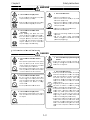 9
9
-
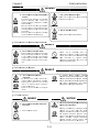 10
10
-
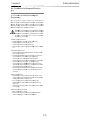 11
11
-
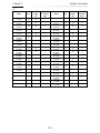 12
12
-
 13
13
-
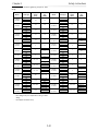 14
14
-
 15
15
-
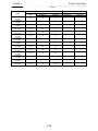 16
16
-
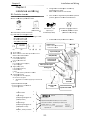 17
17
-
 18
18
-
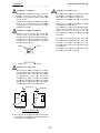 19
19
-
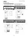 20
20
-
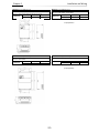 21
21
-
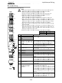 22
22
-
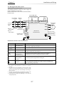 23
23
-
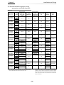 24
24
-
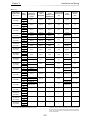 25
25
-
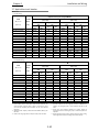 26
26
-
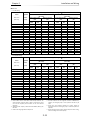 27
27
-
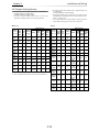 28
28
-
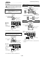 29
29
-
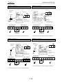 30
30
-
 31
31
-
 32
32
-
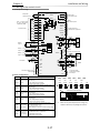 33
33
-
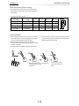 34
34
-
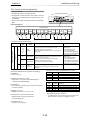 35
35
-
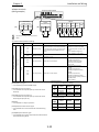 36
36
-
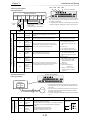 37
37
-
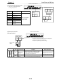 38
38
-
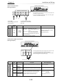 39
39
-
 40
40
-
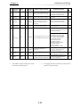 41
41
-
 42
42
-
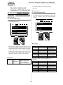 43
43
-
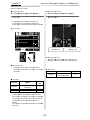 44
44
-
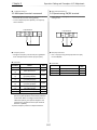 45
45
-
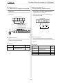 46
46
-
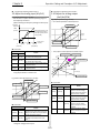 47
47
-
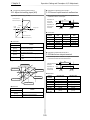 48
48
-
 49
49
-
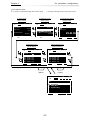 50
50
-
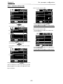 51
51
-
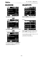 52
52
-
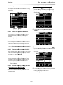 53
53
-
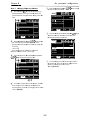 54
54
-
 55
55
-
 56
56
-
 57
57
-
 58
58
-
 59
59
-
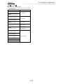 60
60
-
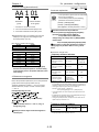 61
61
-
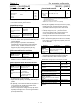 62
62
-
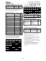 63
63
-
 64
64
-
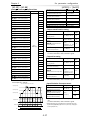 65
65
-
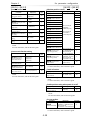 66
66
-
 67
67
-
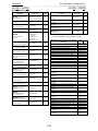 68
68
-
 69
69
-
 70
70
-
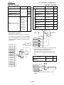 71
71
-
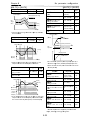 72
72
-
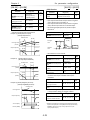 73
73
-
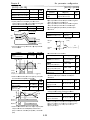 74
74
-
 75
75
-
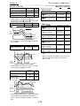 76
76
-
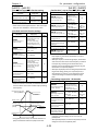 77
77
-
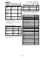 78
78
-
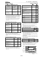 79
79
-
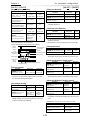 80
80
-
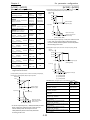 81
81
-
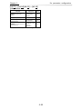 82
82
-
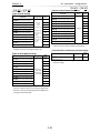 83
83
-
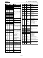 84
84
-
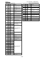 85
85
-
 86
86
-
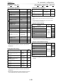 87
87
-
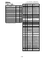 88
88
-
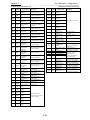 89
89
-
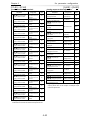 90
90
-
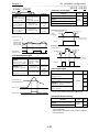 91
91
-
 92
92
-
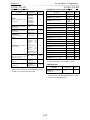 93
93
-
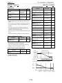 94
94
-
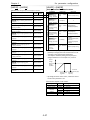 95
95
-
 96
96
-
 97
97
-
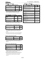 98
98
-
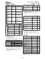 99
99
-
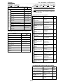 100
100
-
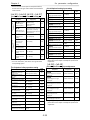 101
101
-
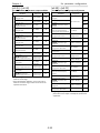 102
102
-
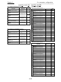 103
103
-
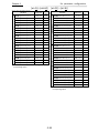 104
104
-
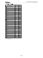 105
105
-
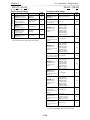 106
106
-
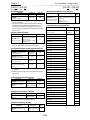 107
107
-
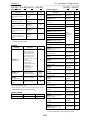 108
108
-
 109
109
-
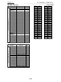 110
110
-
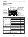 111
111
-
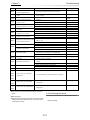 112
112
-
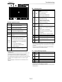 113
113
-
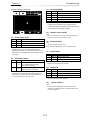 114
114
-
 115
115
-
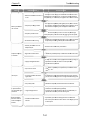 116
116
-
 117
117
-
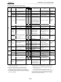 118
118
-
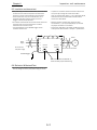 119
119
-
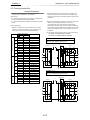 120
120
-
 121
121
-
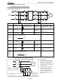 122
122
-
 123
123
-
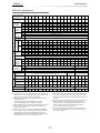 124
124
-
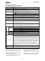 125
125
-
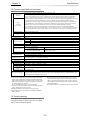 126
126
-
 127
127
-
 128
128
-
 129
129
-
 130
130
-
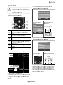 131
131


Ask a question and I''ll find the answer in the document
Finding information in a document is now easier with AI
Related papers
-
Hitachi P1-00044-L User manual
-
Hitachi L100 IP Series User manual
-
Hitachi SJ700D-550L Quick Reference Manual
-
-
Hitachi SJ Series Safety Function Manual
-
-
Hitachi WJ200-002S Quick Reference Manual
-
-
-
Other documents
-
Toshiba Welding System VF-A7 User manual
-
 Powtran PI500 220F3 User manual
-
-
ACP Speecon 7200M3 User manual
-
 AE-TECHNOLOGY AE-L User manual
-
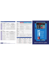 IMO Jaguar VXR2A5-4 Quick Reference Manual
-
Ultratec EZcom PRO User manual
-
Hyundai N700E 037 HF User manual
-
Toshiba VF-S11 User manual
-
Baumer HS35F Installation and Operating Instructions


