Page is loading ...

Be sure this information reaches the operator.
You can get extra copies through your supplier.
These INSTRUCTIONS are for experienced operators. If you are not fully familiar with the principles of operation
and safe practices for arc welding equipment, we urge you to read our booklet, "Precautions and Safe Practices
for Arc Welding, Cutting, and Gouging," Form 52-529. Do NOT permit untrained persons to install, operate, or
maintain this equipment. Do NOT attempt to install or operate this equipment until you have read and fully
understand these instructions. If you do not fully understand these instructions, contact your supplier for
further information. Be sure to read the Safety Precautions before installing or operating this equipment.
F-15-332-B
July, 1998
INSTRUCTION MANUAL
352CV & 482CV
This manual provides complete instructions for the following power sources starting with Serial No. MORI613036,
March, 1996:
ESAB ITEM NO. 36377 - 352CV - 230/460 vac, 3 ph., 60 Hz
ESAB ITEM NO. 36378 - 352CV - 230/460/575 vac, 3ph., 60 Hz
*ESAB ITEM NO. 36379 - 482CV - 230/460 vac, 3 ph., 60 Hz
ESAB ITEM NO. 36380 - 482CV - 220/400 vac, 3 ph., 50 Hz
ESAB ITEM NO. 36381 - 482CV - 220/400 vac, 3 ph., 50 Hz CE Label
* Manufactured for export services only.
NOTE: 352CV and 482CV were originally called V-352 and V-382 respectively.
DC WELDING POWER SOURCES

2
USER RESPONSIBILITY
This equipment will perform in conformity with the description thereof contained in this manual and accompa-
nying labels and/or inserts when installed, operated, maintained and repaired in accordance with the instruc-
tions provided. This equipment must be checked periodically. Malfunctioning equipment should not be used.
Parts that are broken, missing, worn, distorted or contaminated should be replaced immediately. Should such
repair or replacement become necessary, the manufacturer recommends that a telephone or written request
for service advice be made to the Authorized Distributor from whom purchased.
This equipment or any of its parts should not be altered without the prior written approval of the manufacturer.
The user of this equipment shall have the sole responsibility for any malfunction which results from improper
use, faulty maintenance, damage, improper repair or alteration by anyone other than the manufacturer or a
service facility designated by the manufacturer.
TABLE OF CONTENTS
SECTION TITLE PAGE
PARAGRAPH
SECTION 1 DESCRIPTION ......................................... 7
1.1 General ..................................................... 7
1.2 Receiving-Handling ................................... 7
1.3 Description ................................................ 7
1.3.1 Power Source............................................ 8
1.3.2 Volt-Ampere Characteristics ..................... 8
1.4 Optional Accessories ................................ 8
1.4.1 Remote Control Kit ................................... 8
1.4.2 HC-3B Remote Voltage and Contactor
Hand Pendant Control ........................... 8
1.4.3 TR-23A Truck Kit ...................................... 8
1.4.4 Swivel Mount Kit ....................................... 8
1.4.5 External Grounding Conductor
Protection Kit ......................................... 8
1.4.6 Automatic Fan Kit ..................................... 8
1.5 Safety ........................................................ 8
SECTION 2 INSTALLATION ........................................ 9
2.1 Location ..................................................... 9
2.2 Receiving, Unpacking and Placement ...... 9
2.3 Primary (Input) Electrical Connection ....... 9
2.4 Secondary (Output) Welding
Connections ........................................ 11
2.5 Control Connections ............................... 11
2.5.1 Wire Feeder Control ............................... 11
2.5.2 Remote Control ....................................... 11
2.5.3 Auxiliary 115 V ac Receptacle ................ 11
2.5.4 42V Circuit Breaker (CB1) ...................... 11
2.5.5 115V Circuit Breaker (CB2) .................... 11
SECTION TITLE PAGE
PARAGRAPH
SECTION 3 OPERATION ........................................... 13
3.1 Controls ................................................... 13
3.1.1 Power Switch (ON-OFF) ......................... 13
3.1.2 Contactor, On/Remote Switch ................ 13
3.1.3 Voltage, Panel/Remote Switch ............... 13
3.1.4 Voltage Control ....................................... 13
3.1.5 Over Temperature Indicator ................... 13
3.1.6 Voltmeter and Ammeter .......................... 14
3.1.7 Fault Indicator ......................................... 14
3.1.8 Over Current Protection .......................... 14
3.2 Sequence of Operation ........................... 14
3.2.1 General Procedures for Mig Welding ..... 14
3.2.2 Specific Procedures for Mig Welding ...... 14
SECTION 4 MAINTENANCE ..................................... 15
4.1 General ................................................... 15
4.2 Cleaning .................................................. 15
4.3 Inspection and Service ........................... 15
4.3.1 Fan Motor ................................................ 15
4.3.2 Transformer ............................................ 15
4.3.3 Wire Feeder and Control Circuits ........... 15
4.3.4 Over Temperature Protection ................. 15
4.3.5 Digital Voltmeter/Ammeter Calibration .. 15
SECTION 5 TROUBLESHOOTING ........................... 16
5.1 General ................................................... 16
5.2 Testing and Replacing Bridge
Assembly Components ....................... 16
SECTION 6 PARTS .................................................... 18
6.1 General ................................................... 18
6.2 Ordering .................................................. 18

3
WARNING: These Safety Precautions are for
your protection. They summarize precaution-
ary information from the references listed in
Additional Safety Information section. Before
performing any installation or operating procedures, be
sure to read and follow the safety precautions listed below
as well as all other manuals, material safety data sheets,
labels, etc. Failure to observe Safety Precautions can result
in injury or death.
PROTECT YOURSELF AND OTHERS --
Some welding, cutting, and gouging
processes are noisy and require ear
protection. The arc, like the sun, emits
ultraviolet (UV) and other radiation and
can injure skin and eyes. Hot metal can cause burns.
Training in the proper use of the processes and equip-
ment is essential to prevent accidents. Therefore:
1. Always wear safety glasses with side shields in any work
area, even if welding helmets, face shields, and goggles
are also required.
2. Use a face shield fitted with the correct filter and cover
plates to protect your eyes, face, neck, and ears from
sparks and rays of the arc when operating or observing
operations. Warn bystanders not to watch the arc and
not to expose themselves to the rays of the electric-arc
or hot metal.
3. Wear flameproof gauntlet type gloves, heavy long-sleeve
shirt, cuffless trousers, high-topped shoes, and a weld-
ing helmet or cap for hair protection, to protect against
arc rays and hot sparks or hot metal. A flameproof apron
may also be desirable as protection against radiated
heat and sparks.
4. Hot sparks or metal can lodge in rolled up sleeves,
trouser cuffs, or pockets. Sleeves and collars should be
kept buttoned, and open pockets eliminated from the
front of clothing
5. Protect other personnel from arc rays and hot sparks
with a suitable non-flammable partition or curtains.
6. Use goggles over safety glasses when chipping slag or
grinding. Chipped slag may be hot and can fly far.
Bystanders should also wear goggles over safety glasses.
FIRES AND EXPLOSIONS -- Heat from
flames and arcs can start fires. Hot slag
or sparks can also cause fires and ex-
plosions. Therefore:
1. Remove all combustible materials well away from the
work area or cover the materials with a protective non-
flammable covering. Combustible materials include wood,
cloth, sawdust, liquid and gas fuels, solvents, paints and
coatings, paper, etc.
2. Hot sparks or hot metal can fall through cracks or
crevices in floors or wall openings and cause a hidden
smoldering fire or fires on the floor below. Make certain
that such openings are protected from hot sparks and
metal.“
3. Do not weld, cut or perform other hot work until the
workpiece has been completely cleaned so that there
are no substances on the workpiece which might pro-
duce flammable or toxic vapors. Do not do hot work on
closed containers. They may explode.
4. Have fire extinguishing equipment handy for instant use,
such as a garden hose, water pail, sand bucket, or
portable fire extinguisher. Be sure you are trained in its
use.
SAFETY PRECAUTIONS
11/95
5. Do not use equipment beyond its ratings. For example,
overloaded welding cable can overheat and create a fire
hazard.
6. After completing operations, inspect the work area to
make certain there are no hot sparks or hot metal which
could cause a later fire. Use fire watchers when neces-
sary.
7. For additional information, refer to NFPA Standard 51B,
"Fire Prevention in Use of Cutting and Welding Pro-
cesses", available from the National Fire Protection Asso-
ciation, Batterymarch Park, Quincy, MA 02269.
ELECTRICAL SHOCK -- Contact with live
electrical parts and ground can cause
severe injury or death. DO NOT use AC
welding current in damp areas, if move-
ment is confined, or if there is danger of
falling.
1. Be sure the power source frame (chassis) is connected
to the ground system of the input power.
2. Connect the workpiece to a good electrical ground.
3. Connect the work cable to the workpiece. A poor or
missing connection can expose you or others to a fatal
shock.
4. Use well-maintained equipment. Replace worn or dam-
aged cables.
5. Keep everything dry, including clothing, work area, cables,
torch/electrode holder, and power source.
6. Make sure that all parts of your body are insulated from
work and from ground.
7. Do not stand directly on metal or the earth while working
in tight quarters or a damp area; stand on dry boards or
an insulating platform and wear rubber-soled shoes.
8. Put on dry, hole-free gloves before turning on the power.
9. Turn off the power before removing your gloves.
10. Refer to ANSI/ASC Standard Z49.1 (listed on next page)
for specific grounding recommendations. Do not mistake
the work lead for a ground cable.
ELECTRIC AND MAGNETIC FIELDS —
May be dangerous. Electric current flow-
ing through any conductor causes lo-
calized Electric and Magnetic Fields
(EMF). Welding and cutting current cre-
ates EMF around welding cables and
welding machines. Therefore:
1. Welders having pacemakers should consult their physi-
cian before welding. EMF may interfere with some pace-
makers.
2. Exposure to EMF may have other health effects which are
unknown.
3. Welders should use the following procedures to minimize
exposure to EMF:
A. Route the electrode and work cables together. Secure
them with tape when possible.
B. Never coil the torch or work cable around your body.
C. Do not place your body between the torch and work
cables. Route cables on the same side of your body.
D. Connect the work cable to the workpiece as close as
possible to the area being welded.
E. Keep welding power source and cables as far away
from your body as possible.

4
FUMES AND GASES -- Fumes and
gases, can cause discomfort or harm,
particularly in confined spaces. Do
not breathe fumes and gases. Shield-
ing gases can cause asphyxiation.
Therefore:
1. Always provide adequate ventilation in the work area by
natural or mechanical means. Do not weld, cut, or gouge
on materials such as galvanized steel, stainless steel,
copper, zinc, lead, beryllium, or cadmium unless positive
mechanical ventilation is provided. Do not breathe fumes
from these materials.
2. Do not operate near degreasing and spraying opera-
tions. The heat or arc rays can react with chlorinated
hydrocarbon vapors to form phosgene, a highly toxic
gas, and other irritant gases.
3. If you develop momentary eye, nose, or throat irritation
while operating, this is an indication that ventilation is not
adequate. Stop work and take necessary steps to im-
prove ventilation in the work area. Do not continue to
operate if physical discomfort persists.
4. Refer to ANSI/ASC Standard Z49.1 (see listing below)
for specific ventilation recommendations.
CYLINDER HANDLING -- Cylinders, if
mishandled, can rupture and violently
release gas. Sudden rupture of cylin-
der, valve, or relief device can injure or
kill. Therefore:
1. Use the proper gas for the process and use the proper
pressure reducing regulator designed to operate from
the compressed gas cylinder. Do not use adaptors.
Maintain hoses and fittings in good condition. Follow
manufacturer's operating instructions for mounting regu-
lator to a compressed gas cylinder.
2. Always secure cylinders in an upright position by chain
or strap to suitable hand trucks, undercarriages, benches,
walls, post, or racks. Never secure cylinders to work
tables or fixtures where they may become part of an
electrical circuit.
3. When not in use, keep cylinder valves closed. Have
valve protection cap in place if regulator is not con-
nected. Secure and move cylinders by using suitable
hand trucks. Avoid rough handling of cylinders.
4. Locate cylinders away from heat, sparks, and flames.
Never strike an arc on a cylinder.
5. For additional information, refer to CGA Standard P-1,
"Precautions for Safe Handling of Compressed Gases in
Cylinders", which is available from Compressed Gas
Association, 1235 Jefferson Davis Highway, Arlington,
VA 22202.
EQUIPMENT MAINTENANCE -- Faulty or im-
properly maintained equipment can cause
injury or death. Therefore:
1. Always have qualified personnel perform the installa-
tion, troubleshooting, and maintenance work. Do not
perform any electrical work unless you are qualified to
perform such work.
2. Before performing any maintenance work inside a power
source, disconnect the power source from the incoming
electrical power.
3. Maintain cables, grounding wire, connections, power cord,
and power supply in safe working order. Do not operate
any equipment in faulty condition.
4. Do not abuse any equipment or accessories. Keep
equipment away from heat sources such as furnaces, wet
conditions such as water puddles, oil or grease, corrosive
atmospheres and inclement weather.
5. Keep all safety devices and cabinet covers in position and
in good repair.
6. Use equipment only for its intended purpose. Do not
modify it in any manner.
ADDITIONAL SAFETY INFORMATION -- For
more information on safe practices for elec-
tric arc welding and cutting equipment, ask
your supplier for a copy of "Precautions and
Safe Practices for Arc Welding, Cutting and
Gouging", Form 52-529.
The following publications, which are available from the
American Welding Society, 550 N.W. LeJuene Road, Miami,
FL 33126, are recommended to you:
1. ANSI/ASC Z49.1 - "Safety in Welding and Cutting"
2. AWS C5.1 - "Recommended Practices for Plasma Arc
Welding"
3. AWS C5.2 - "Recommended Practices for Plasma Arc
Cutting"
4. AWS C5.3 - "Recommended Practices for Air Carbon Arc
Gouging and Cutting"
5. AWS C5.5 - "Recommended Practices for Gas Tungsten
Arc Welding“
6. AWS C5.6 - "Recommended Practices for Gas Metal Arc
Welding"“
7. AWS SP - "Safe Practices" - Reprint, Welding Handbook.
8. ANSI/AWS F4.1, "Recommended Safe Practices for Weld-
ing and Cutting of Containers That Have Held Hazardous
Substances."
This symbol appearing throughout this manual
means Attention! Be Alert! Your safety is
involved.
The following definitions apply to DANGER, WARNING,
CAUTION found throughout this manual:
Used to call attention to immediate haz-
ards which, if not avoided, will result in
immediate, serious personal injury or loss
of life.
Used to call attention to potential haz-
ards which could result in personal injury
or loss of life.
Used to call attention to hazards which
could result in minor personal injury.

7
SECTION 1
DESCRIPTION
When requesting information concerning this equip-
ment, it is essential that Item number, Serial number
and Model number of the equipment be supplied.
1.3 DESCRIPTION
The 352CV and 482CV are designed for Mig short
circuiting, spray and flux cored arc welding (GMAW
and FCAW). Table 1-1 outlines the electrical and
physical specifications of the available models.
1.3.1 Power Source
The power source is a constant potential, Silicon
Controlled Rectifier (SCR), three phase, star-con-
nected transformer/rectifier type dc unit with solid
state contactor and control circuitry. It provides the
volt-ampere characteristics desired for conventional
Mig and flux cored arc welding.
1.1 GENERAL
This manual has been prepared for use by an expe-
rienced operator. It provides information to familiar-
ize the operator with the design, installation and
operation of the 352CV & 4 8 2 CV model power sources.
DO NOT attempt to install or operate this equipment
until you have read and fully understood these in-
structions. The information presented here should
be given careful consideration to ensure optimum
performance of this equipment.
1.2 RECEIVING-HANDLING
Upon receipt, remove all packing material and care-
fully inspect for any damage that may have occurred
during shipment. Any claims for loss or damage that
may have occurred in transit must be filed by the
purchaser with the carrier. A copy of the bill of lading
and freight bill will be furnished by the carrier on
request.
NOTE: The 352cv/382cv may also operate from a 200 (208)-volt a.c. primary input using the 230-volt changeover connections. However,
when connected to this source (200-volt), the output voltage is derated from 34-volts to 32-volts @ 450 amps.
The 482cv - 50 Hz may operate from 380 vac or 415 vac primary input when using the 400 vac changeover connection. When using this
connection, the output voltage is derated from 34 v to 32 v.
1
2
2
1
Table 1-1. Specifications for 352CV and 482CV
1
0
OPEN CIRCUIT VOLTAGE (U ) 45 Vdc
RATED
OUTPUT
DUTY CYCLE 60% 100%
Current (I ) 450 A 350 A
Voltage (U ) 34 V 32 V
RATED
INPUT
3 Phase
60 Hz
Volts (U ) Current (I ) Flat Current (I ) Flat
(208)230 V (66)60 A (55)50 A
460 V 30 A 25 A
575 V 24 A 20 A
50 Hz 220/400(380-415) V 62/35 (37-34) A 52/29 (31-28) A
Power Factor at Rated Output 83%
Welding Range 450A/34V - 30 A/12 V
Auxiliary Power 115 V ac @ 10 A, 60 Hz
PHYSICAL SPECIFICATIONS
60 Hz. 50 Hz.
Height
(without lift eye)
25.0" (62.2 cm)
Width
18.8" (48.3 cm)
Depth
32.5" (81.9 cm)
Net Weight
331 lbs (150 kg) 371 lbs (168 kg)
Shipping Weight
341 lbs (155 kg) 381 lbs (173 kg)

DESCRIPTIONSECTION 1
8
60
50
0
0
10
20
30
40
100
300 400
Amperes
Volts
500200
MIN.
Figure 1-1. Volt-Ampere Curves
1.4.6 Automatic Fan Kit (Item No. 36707)
With this kit installed, the fan will start to operate when
the welding arc is initiated and will continue to run for
5 minutes after the arc has been extinguished.
NOTE: This option can only be installed in units
manufactured after Serial No. MX-I709000
in which the large R5 resistor was moved
from top center of "A" frame to the base in
front of the fan bracket.
1.5 SAFETY
Before the equipment is put into operation, the safety
section at the front of this manual should be read
completely. This will help avoid possible injury due to
misuse or improper installation.
The definitions relating to the:
safety notations are described at the end of the Safety
Section in the front of this manual read them and
their specific text references carefully.
1.3.2 Volt-Ampere Characteristics
The curves shown in Figure 1-1 represent the volt-
ampere static characteristics for the power source.
The slant of these curves is referred to as the "slope"
and is generally defined as the "voltage drop per 100
amperes of current use". These curves show the
output voltage available at any given output current
from the minimum to the maximum setting of the
voltage control. Because the volt-ampere slope is
fixed, it is possible to select welding conditions by
estimating the open-circuit voltage required for the
load current.
1.4 OPTIONAL ACCESSORIES
1.4.1 Remote Control Kit (Item No. 36010).
This Remote Control Kit consists of a 14 pin recep-
tacle and assembly that permits the use of the HC-3B
Remote Control (Item No. 33838) as described be-
low.
1.4.2 HC-3B Remote Hand Control (Item No.
33838)
This control provides remote output control and pro-
vides a contactor closure switch to close the contactor
making the output terminals hot. The panel/remote
switch on the front panel must be placed in the remote
position when using this accessory.
1.4.3 TR-23A Truck Kit (Item No. 36224)
This truck kit provides complete mobility of the power
source. The kit consists of front castors, rear cylinder
rack and wheels, gas cylinder bracket, cylinder chain,
and pull handle.
1.4.4 Swivel Mount Kit (Item No. 36172)
This kit allows the MIG 2E and MIG 4HD wire feeders
to be mounted to the top of the power source on an
insulated swivel mount. This allows the feeder to
freely rotate, relieving potential wire feed problems
while increasing the working area of the torch.
1.4.5 External Grounding Conductor Protection
Kit (Item No. 36098)
This kit, when installed, will de-energize the power
source output if current flow is detected in the exter-
nal ground conductor. When this happens, the Fault
light on the front control panel will light. It will remain
lit until the fault is corrected or the power source
power switch (S1) is turned off.
MAX.

9
INSTALLATION
SECTION 2
2.1 LOCATION
A proper installation site is necessary for the power
source to provide dependable service. A proper in-
stallation site permits freedom of air movement
through the unit while minimizing exposure to dust,
dirt, moisture, and corrosive vapors. A minimum of 18
inches (46 cm) is required between the side and rear
panels of the power source and the nearest obstruc-
tion. Also, the underside of the power source must be
kept completely free of obstructions.
The selected site should also allow easy removal of
the power source outer enclosure for maintenance.
See Table 1-1 for overall dimensions of the unit.
2.2 RECEIVING, UNPACKING AND
PLACEMENT
A. Immediately upon receipt of the power
source, inspect for damage which may have
occurred in transit. Notify the carrier of any
defects or damage.
B. Remove the power source from the con-
tainer. Remove all packing materials. Check
the container for any loose parts.
C. Check air passages at front and rear of
cabinet, making sure that no packing mate-
rials that may obstruct air flow through the
power source.
D. Install the lifting ring furnished with the power
source into the top of the unit.
For lifting purposes and for keeping dust, mois-
ture, and other foreign material from entering the
power source, the lifting eyebolt must be fully
tightened with a tool.
E. After selecting an installation site (see para-
graph 2.1), place the power source in the
desired location. The unit may be lifted either
by using the lifting ring or by forklift truck. If
a forklift is used for lifting the unit, be sure that
the lift forks are long enough to extend com-
pletely under the base.
Do not use filters on this unit as they would
restrict the volume of intake air required for
proper cooling. Output ratings on this unit are
based on an unobstructed supply of cooling air
drawn over its internal components. Warranty is
void if any type of filtering device is used.
2.3 PRIMARY (INPUT) ELECTRICAL
CONNECTION
This power source is a three-phase unit and must be
connected to a three-phase power supply. It is rec-
ommended that the unit be operated on a dedicated
circuit to prevent impairment of performance due to
an overloaded circuit.
ELECTRIC SHOCK CAN KILL! Before making
electrical input connections to the power source,
"Machinery Lockout Procedures" should be em-
ployed. If the connections are to be made from a
line disconnect switch, place the switch in the off
position and padlock it to prevent inadvertent
tripping . If the connection is made from a fusebox,
remove the corresponding fuses and padlock the
box cover. If it is not possible to use padlocks,
attach a red tag to the line disconnect switch (or
fuse box) warning others that the circuit is being
worked on.
A. The primary power leads must be insulated
copper conductors. Three power leads and
one ground wire are required. Either rubber
covered cable or conduit (flexible or solid)
may be used. Table 2-1 provides recom-
mended input conductors and line fuse sizes.
B. Remove the top cover. Identify primary power
input connections on the power switch, chas-
sis ground lug on the "A" frame, and primary
input terminal board. Refer to Figures 2-1
and 2-2.

10
INSTALLATIONSECTION 2
® Double Link Provided
( ) Connections for 50 Hz units.
Strain Relief
Rear Panel (Inside View)
3 Power Leads
L1
L2
L3
Ground Lead
(Green or Green w/ Yellow Stripe)
Connect to Ground Lug (GND1)
Located on A-Frame, Right Side
ON-OFF Power
Switch (S1)
Recommended Cable Strip Lengths
(220)
Figure 2-1. Connecting Primary Power Leads
(400)
(220)
(220)
(400)
(220)
(220)
(400)
(220)
Table 2-1. Recommended Sizes for Input
Conductors and Line Fuses
Rated Input
at 100% Duty Cycle Rating
Input &
GND
Conductor*
CU/AWG
Fuse Size
Amps
Volts Amps
208
220
230
400
460
575
55
52
50
29
25
20
No. 8
No. 8
No. 8
No. 12
No. 14
No. 14
90
80
80
40
40
30
* Sized per National Code for 80 °C rated copper conductors @
30 °C ambient. Not more than three conductors in raceway or
cable. Local codes should be followed if they specify sizes
other than those listed above.
C. When using the provided strain relief, refer to
Figure 2-1 for proper cable strip lengths. It is
important to follow the cable strip guide to
ensure that if the primary input cable is ever
pulled from the strain relief, the input conduc-
tors will be pulled from the ON/OFF power
switch before the ground lead is pulled from
the ground lug. Once stripped, thread the
input and ground conductors through the
large strain-relief in the rear panel of the
power source. Connect the ground wire to
Figure 2-2. Input Terminal Board
230/460 (220/400) V illustrated with voltage links in the
factory supplied 460 volt configuration.
the terminal lug located on the right rear A-
frame leg inside the power source. Connect
the primary power leads to terminals L1, L2,
and L3 on the input power switch. Secure the
strain relief on the input cable.

11
INSTALLATION
SECTION 2
The output terminals are located on the front panel
(Figure 2-3). Three output terminals are provided.
Two NEGATIVE (-) terminals are located at the bot-
tom right-hand corner and the POSITIVE (+) terminal
is located at the bottom left corner. The output cable
connections will depend on the materials to be welded
and on the welding process desired. Table 2-2 pro-
vides the recommended cable output sizes.
2.5 CONTROL CONNECTIONS
Refer to Figure 2-3.
2.5.1 Wire Feeder Control
The Wire feeder control cable connection is provided
by a 19-pin receptacle (J1) located on the left-hand
side of the power source front panel. This receptacle
will operate all ESAB wire feeders with 19 pin control
cables including the Mig 2E, Mig 4HD, Mig 28A, Mig
35, Digimig, Digimig Dual as well as the UEC-8,
Digimatic II and Analog Interface mechanized con-
trols.
2.5.2 Remote Control (Optional)
This function is provided by an optional 14-pin recep-
tacle (J2) located on the front panel directly below
connector J1. It receives a mating plug from a Hand
Control Assembly (optional). This receptacle is op-
erative only if the panel remote switch on the power
source front panel is in the "Remote" position.
2.5.3 Auxiliary 115 V AC Receptacle
A 115 Vac receptacle is provided to supply power to
accessories such as a water cooler, heated CO
2
regulator, or small hand tools. The receptacle is rated
115 Vac / 10 amps.
2.5.4 - 42V Circuit Breaker (CB1)
The 42V resettable circuit breaker (CB1) protects the
42 volt wire feeder/control circuitry against over cur-
rent. (Table 5-2 provides troubleshooting informa-
tion).
2.5.5 - 115V Circuit Breaker (CB2)
The 115V resettable circuit breaker (CB2) protects
the 115 volt auxiliary receptacle and wire feeder/
control circuitry against over current. (Table 5-2 pro-
vides troubleshooting information).
The chassis must be connected to an approved
electrical ground. Failure to do so may result in
electrical shock, severe burns or death.
D. Check all connections for proper tightness.
Ensure all connections are correct and well-
insulated.
E. Figure 2-2 illustrates the input voltage termi-
nal board and the input voltage link connec-
tions. The particular voltages from which this
power source may be operated are stated on
the rating plate. The voltage links were fac-
tory set for highest voltage stated on the
rating plate. If the power source is to be
operated on another stated input voltage, the
links must be reset for that particular input
voltage. Always verify the input voltage and
check the link arrangement regardless of
factory setting. The voltage links are set up
by reconfiguring the copper link bars to the
silk-screened voltage designations for the
desired voltage.
2.4 OUTPUT WELDING CONNECTIONS
(SECONDARY)
Before making any connections to the power
source output terminals, make sure that all pri-
mary input power to the machine is off.
Table 2-2. Output Cable Sizes (Secondary)
Welding
Current
Total Length (Feet) of
Cable in Weld Circuit*
50 100 150 200 250
100
150
200
250
300
400
500
6
4
3
2
1
2/0
3/0
4
3
1
1/0
2/0
3/0
3/0
3
1
1/0
2/0
3/0
4/0
4/0
2
1/0
2/0
3/0
4/0
4/0
2-2/0
1/0
2/0
3/0
4/0
4/0
2-2/0
2-3/0
* Total cable length includes work and electrode cables. Cable size is based
on direct current, insulated copper conductors, 100-percent duty cycle and
a voltage drop of 4 or less volts. The welding cable insulator must have a
voltage rating that is high enough to withstand the open circuit voltage of
the machine.

12
INSTALLATIONSECTION 2
2.5.2
J2 (14-PIN), (Optional)
2.5.1
(19-PIN) J1
2.5.3
J3, 10 Amperes
2.5.5
2.5.4
Figure 2-3. Connection Diagram
Table 2-3
Recommended Output Inductance Tap Connections
Notes: The above chart shows the recommended output inductance tap connection for Mig Short Circuiting Transfer.
For Mig Spray Arc Transfer (stainless or carbon steel) - use low tap
For Flux Cored Wire (all types) - use low tap
NR - Not Recommended
* The best connection (high tap or low tap) depends on the specific welding application and personal preference.
Output Receptacle
2.4
Stainless Steel
Solid Wires Carbon Steels Solid Wires
Helium/Argon Based
Shielded Gases Argon Based Shielding Gases CO
2
Shielding Gas
Welding .023" .030" .035" .045"
Current All Wire Diameters (0.6mm) (0.8mm) (0.9mm) (1.2mm) All Wire Diameters
£ 100 amps high tap high tap high tap high tap high tap low tap
125 amps high tap high or low* high or low* high or low* high or low* low tap
150 amps high tap N R low tap low tap low tap low tap
³ 200 amps high tap N R N R low tap low tap low tap

SECTION 3
13
OPERATION
Never operate the power source with the cover
removed. In addition to the safety hazards, im-
proper cooling may cause damage to the compo-
nents. Keep side panels closed when unit is
energized. Welding helmet, gloves, and other
personal protection should always be worn when
welding.
3.1 CONTROLS (See Figure 3-1)
3.1.1 Power Switch (ON-OFF)/(I-O)
The power switch is located on the rear panel of the
power source. In the "off" ("O") position, the unit is
shut down; however, power is still present at the
switch itself. To fully shut down the power source,
power must be disconnected at the line disconnect
switch or the fuse box.
With the switch in the "on" ("I") position, power is
provided to the main transformer and the low voltage
control circuitry.
3.1.1.1 Power Indicator
This white light will indicate that the power switch is
in the on position and power has been applied to the
main transformer and low voltage circuitry.
3.1.6
3.1.1
(on rear panel)
Figure 3-1. Control Locations
3.1.1.1
3.1.5
3.1.7
3.1.4
3.1.2
3.1.3
V
3.1.2 Contactor, On/Remote Switch
The Contactor Control switch is located on the front
panel of the power source. In the on position, the
solid state contactor is energized and output power is
available at the output terminals. The "Remote" posi-
tion allows the solid state contactor to be controlled
from a remote Mig wire feeder or mechanized sub arc
control.
3.1.3 Voltage, Panel/Remote Switch
With this switch in the Panel position, output voltage
is controlled by adjusting the voltage potentiometer
on the front panel to the desired output. In the
Remote position, output is controlled using an op-
tional remote voltage control via receptacle J2 or at
the wire feeder.
3.1.4 Voltage Control
This control allows the operator to adjust the output
voltage. Placing the Panel/Remote switch in the
Remote position disables the voltage control on the
front panel.
3.1.5 Over Temperature Indicator (Temp)
This amber light will indicate when an internal
overheating condition has occurred and one of the
thermal switches has opened. User control of the
solid state contactor will be interrupted and power
source output will shut down to protect critical compo-
nents. Once cooled to a safe temperature, the ther-
mal switch will automatically reset and output control
will be restored.

14
SECTION 3 OPERATION
the main wall disconnect switch or reinstall
fuses in the fuse box.
3.2.2 Specific Procedures for MIG Welding
(GMAW)
A. Set the Voltage (panel/remote) switch to the
desired setting.
B. Set the contactor switch to "Remote".
ELECTRIC SHOCK CAN KILL! When the contactor
switch is in the "ON" position, output power will
be present thoughout the welding circuit; ie.
cables, wire feeder, wire spool, drive stand, gun,
and electrode. Be sure all are clear of the work-
piece or arcing will result.
C. Set the power switch on the rear panel to the
"on" ("I") position.
D. To preset the approximate welding voltage,
place the Contactor switch to the "on" posi-
tion. This will energize the power source
output, allowing the voltage to be preset
using the Voltage Control potentiometer and
observing the voltmeter.
E. After setting the desired voltage condition,
turn the contactor switch back to the re-
mote position. This position requires a re-
mote start control in order to start the welding
sequence.
F. Refer to Table 2-3 for the recommended
output inductance tap connections. The in-
ductance tap connection depends on the
combination of material type being welded,
shielding gas and the welding process being
used.
G. Begin welding. Observe the voltmeter, am-
meter, and the weld. Readjust the voltage
and wire feed speed settings as necessary to
obtain a satisfactory weld.
H. When welding is completed, release torch
switch. (This action will deenergize the power
source solid state contactor and remove dc
power from the output terminals.)
3.1.6 Voltmeter and Ammeter
A digital voltmeter and ammeter provides an accu-
rate indication of dc output voltage and current.
3.1.7 Fault Indicator
If an optional External Ground Conductor Protection
Kit was installed, this red light, when lit, will indicate
that current was flowing through the external ground
conductor. The power source output terminals are
de-energized and the fault must be corrected before
resuming operation.
3.1.8 Over Current Protection
The 352CV and 482CV incorporate automatic over
current protection. If an over current condition oc-
curs, the automatic circuitry will fold back the output
current to a level that will prevent damage to the
power source. The power source will remain in this
low current fold back mode until the arc is broken,
the torch trigger is released or the contactor switch is
reset.
3.2 SEQUENCE OF OPERATION
Prior to performing the steps below, open the wall
disconnect switch or remove the fuse from the fuse
box to electrically isolate the power source.
ELECTRIC SHOCK CAN KILL! "Machinery Lock-
out Procedures" should be employed. If it is not
possible to use padlocks, attach a red tag to the
line disconnect switch (or fuse box) warning
others that the circuit is being worked on.
3.2.1 General Procedures for MIG Welding
(GMAW)
A. Make the secondary output connections to
the positive and negative output receptacles.
B. Make the control connections. Refer to the
appropriate wire feeder, mechanized con-
trol, and/or torch instruction booklets for ad-
ditional process requirements or control con-
nections.
C. If primary input connections have been made
to the power switch, and on the input terminal
board to match the incoming voltage, close

SECTION 4
MAINTENANCE
15
4.1 GENERAL
If this power source does not operate properly,
stop work immediately and investigate the cause
of the malfunction. Maintenance work must be
performed by an experienced person, and electri-
cal work by a trained electrician. Do not permit
untrained persons to inspect, clean, or repair this
power source. Use only recommended replace-
ment parts.
Be sure that the branch circuit or main discon-
nect switch is off, or electrical input fuses are
removed, before attempting any inspection or
work inside the power source. Placing the power
switch in the off position does not remove all
power from inside the power source.
4.2 CLEANING
Periodically, remove the cover from the power source
and blow accumulated dust and dirt from the air
passages and interior components by using clean
low pressure air. The frequency of cleaning required
depends upon the environment in which the power
source is used.
It is imperative that all air passages be kept as clean
as possible in order to allow adequate air flow to
provide proper cooling.
After cleaning with low pressure air, check for and
tighten any loose hardware, including all electrical
connections. Check for frayed and/or cracked insu-
lation on all power cables and replace if necessary.
Failure to replace worn or damaged cables may
result in a bare cable touching a grounded object.
The resulting electrical arc may injure unpro-
tected eyes and will present a serious fire hazard.
Body contact with a bare cable, connector, or
conductor may result in severe electrical shock,
causing serious burns or death.
4.3 INSPECTION AND SERVICE
Keep the power source dry, free of oil and grease,
and protected at all times from damage by hot metal
and sparks.
4.3.1 Fan Motor
Keep the fan motor free of accumulated dust and lint.
4.3.2 Transformer
Other than periodically cleaning the dust and dirt from
the transformer, no maintenance is required. Ensure
that only clean, dry, low pressure air is used.
4.3.3 Wire Feeder and Control Circuits
These circuits are protected by two 10 amp circuit
breakers mounted in the front panel. If these open,
the contactor and wire feeder will not operate.
4.3.4 Over Temperature Protection
If the power source reaches an abnormally high
internal temperature, the thermal protection will
deenergize the contactor circuit, shutting down the
power source but leaving the cooling fan on. After the
power source has cooled to a safe level, the thermal
protection will automatically reset. While deenerigized,
the contactor and wire feeder cannot be operated.
4.3.5 Digital Voltmeter/Ammeter Calibration
To verify the accuracy of the digital voltmeter/amme-
ter combination, the following procedure can be per-
formed periodically:
1. Place the Panel/Remote switch in Panel position.
2. Disconnect cables from the output terminals and
then connect an accurate DC voltmeter to the
output terminals.
3. Place the Contactor switch in the On position.
4. With the primary input power on, turn the Voltage
control knob until you get 25V on the DC voltme-
ter. Compare the reading with the reading on the
digital voltmeter on the front panel.
5. If there is a difference in the voltage readings,
open front control panel by removing the two
mounting screws from the upper corners, re-
move meter board from its four mounting posts,
and adjust the trimpot (R13) on the meter board
with a small screwdriver until the digital meter
reading matches the DC voltmeter reading. When
satisfied, reassemble meter board and front con-
trol panel.

16
TROUBLESHOOTING
SECTION 5
6. Check the gate circuit on the SCRs by install-
ing a jumper from the gate lead to the anode
of the SCR. The meter should read less than
5 ohms. Remove the jumper from the gate.
The meter reading should increase (30-50
ohms).
IMPORTANT
When replacing SCRs, make sure mounting sur-
faces are clean. Using Alcoa No. 2 EJC Electrical
Joint Compound or an equivalent, apply a thin coat
to the SCR mounting surface and positively locate in
place on the heatsinks. Place the clamp in position
with the bolts through the holes in the heatsinks and
proceed as follows:
1. Tighten the bolts evenly until finger tight noting
that the nuts are not rotating.
2. Tighten the bolts 3/4 turn plus an 1/8 turn using
a socket wrench on the bolt heads and rotating
only in 1/4 turn increments plus 1/8 turn alter-
nating between the bolts noting that the nuts are
not rotating.
Table 5-1. PCB Voltage Tests*
NOTE
All voltage readings are taken with the front access
panel open and the power switch "ON".
Electrical service and repair should be attempted
only by a trained electrician.
5.1 GENERAL
DISCONNECT primary power at wall switch, or
circuit breaker, before attempting inspection or
work inside the power source.
If the power source is operating improperly, the
following troubleshooting information may be used to
locate the source of the trouble.
Check the problem against the symptoms in the
following troubleshooting guide (Table 5-2.) The
remedy for the problem may be quite simple. If the
cause cannot be quickly located, open up the unit and
perform a simple visual inspection of all the compo-
nents and wiring. Check for proper terminal connec-
tions, loose or burned wiring or components, blown
fuses, bulged or leaking capacitors, or any other sign
of damage or discoloration.
5.2 TESTING AND REPLACING BRIDGE
ASSEMBLY COMPONENTS
The SCRs used in the power source are devices
which allow current to flow in only one direction. The
SCRs are designed to provide long trouble-free op-
eration; however, should a failure occur, they may
require replacement.
A. Testing SCRs.
1. Remove top and right side panel from the
power source.
2. Locate the main rectifier assembly contain-
ing the SCRs.
3. Electrically isolate main bridge assembly by
disconnecting the capacitor bank and resis-
tor R5.
4. With the ohmmeter on RX1 scale, place the
positive lead on the anode (end of SCR with
screw threads) and the negative lead on the
cathode (positive output terminal on the front
panel). The meter should read minimum of
5 megohms.
5. Reverse leads and check each SCR. All
readings should again show high resistance.
The SCRs are bad if they show low resis-
tance in either direction.
SCR VOLTAGES (OUTPUT)
FROM TO READING
P8-5 OTB+ +10 V dc
P8-7 OTB+ 0-10 V dc**
P6-6 (SCR1)
P6-5 (SCR2)
P6-4 (SCR3)
P6-3 (SCR4)
P6-2 (SCR5)
P6-1 (SCR6)
OTB+ .3 V dc with
contactor on
* Refer to Schematic Diagram
** Varies with VCP (R1)

17
TROUBLESHOOTING
SECTION 5
Table 5-2. Troubleshooting Guide
CONDITION ACTION
Unit Inoperative A.
B.
C.
D.
E.
F.
G.
No input power. Check main line (user’s) switch fuses --replace if needed.
Poor or improper input (terminal board) connections.
Defective on/off switch on rear panel -- replace.
Main transformer overheating. Also check for proper cooling, proper primary hookup, or
shorted turn on secondary.
Fan motor not operating -- check motor and leads.
Ground fault indicator "ON". - Check for cause and correct. Turn power switch "OFF" then
"ON" to reset.
Loss of primary phase. Check that LED on control PCB is lit. If not, find & replace defective
fuse.
No Output -- Fan
Running
A.
B.
C.
D.
E.
Poor or improper electrical input -- check input connections on TB.
Poor connections at output terminals/work station -- check, tighten or replace.
Main transformer overheating -- thermal switches tripped due to restricted cooling
air. Temperature light on front panel will be lit. Let unit cool down.
Solid-state breaker tripped due to current overload.
PC board defective or loose PC board connector(s) -- if loose, reinsert; if
defective, replace.
Limited Output or
Low Open-Circuit
Voltage
A.
B.
C.
D.
Input voltage jumper links on terminal board improperly set check for proper
voltage.
Poor output connections. Take apart, clean, and reassemble.
Unit may be single phasing -- check incoming power for three phases.
Panel-Remote switch in Remote position and remote voltage pot disabled.
Erratic Weld Current A.
B.
C.
D.
E.
Welding cable size too small -- use correct cables.
Loose welding cable connection (will usually get hot) -- tighten connections.
Improper wire feeder setup.
Defective SCR in bridge rectifier.
PC board defective -- replace.
High Output, No
Voltage Control
A. PC board defective or loose -- reset and/or replace board.
No 115 Volt ac
Output
A. Circuit breaker tripped. Check 42V CB1 and 115V CB2 -- Reset.
Line Fuse Blows
When Power Source
is First Turned On
A.
B.
Shorted SCR in Main Bridge-- replace.
Shorted capacitor in Capacitor Bank.
Wire Feeder is
Inoperative
A.
B.
Loose feeder control cable -- Check and tighten all connections.
A Circuit Breaker tripped-- Check 42V CB1 and 115V CB2 -- Reset.
Wire Sparks and
Sticks to Workpiece
at End of Weld
A.
B.
Allow 2 to 4 seconds for capacitor banks to discharge after completing the weld
and before touching wire to workpiece.
If doubling the discharge rate is desired (twice as fast), change R5 (16 ohm, 300
watt) resistor to 8 ohm, 300 watt resistor (P/N 17300008). To quadruple the
discharge rate (four times as fast), two 8 ohm resistors may be connected in
parallel in place of R5.

SECTION 6
REPLACEMENT PARTS
18
6.1 GENERAL
Always provide the series or serial number of the unit
on which the parts will be used. The serial number is
stamped on the unit nameplate.
6.2 ORDERING
To assure proper operation, it is recommended that
only genuine ESAB parts and products be used with
this equipment. The use of non-ESAB parts may void
your warranty.
Replacement parts may be ordered from your ESAB
distributor or from:
ESAB Welding & Cutting Products
Attn: Customer Service Dept.
PO Box 100545, Ebenezer Road
Florence, SC, 29501-0545
Be sure to indicate any special shipping instructions
when ordering replacement parts.
To order parts by phone, contact ESAB at 1-843-664-
5540. Orders may also be faxed to 1-800-634-7548.
Be sure to indicate any special shipping instructions
when ordering replacement parts.
Refer to the Communication Guide located on the
back cover page for a list of customer service phone
numbers.

REPLACEMENT PARTS
SECTION 6
19
Figure 5-1. Schematic Diagram - 352CV/482CV, 230/460 vac, 60 Hz, 3 Phase and 220/400 vac, 50 Hz, 3 Phase
NOTE: Recent modifications to the power source may not be reflected in this
schematic. For up-to-date information on your model, refer to the schematic
on the inside cover of the power source.
D-36437-D

SECTION 6
REPLACEMENT PARTS
20
Figure 5-2. Wiring Diagram - 352CV/482CV - 230/460 vac, 60 Hz, 3 Phase and 220/400 vac, 50 Hz, 3 Phase
D-36438-D

REPLACEMENT PARTS
SECTION 6
21
Figure 5-3. 352CV Schematic Diagram - 230/460/575 vac, 60 Hz, 3 Phase
NOTE: Recent modifications to the power source may not be reflected in this
schematic. For up-to-date information on your model, refer to the schematic
on the inside cover of the power source.
D-36439-C

REPLACEMENT PARTS
SECTION 6
23
4, 6
7, 8
352CV
Figure 6-1. 352CV/482CV Power Source (Front View)
ESAB ITEM NO. 36380 - 482CV - 220/400 vac, 3 ph., 50 Hz
ESAB ITEM NO. 36381 - 482
CV - 220/400 vac, 3 ph., 50 Hz CE Label
ESAB ITEM NO. 36377 - 352
CV - 230/460 vac, 3 ph., 60 Hz
ESAB ITEM NO. 36378 - 352CV - 230/460/575 vac, 3ph., 60 Hz
ESAB ITEM NO. 36379 - 482CV - 230/460 vac, 3 ph., 60 Hz
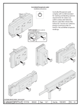
* Starting with Serial No. MORI621001, the square-shape outlet 952219 replaced the round-shape outlet 951033. 952219 will not fit in front
panel of prior manufactured units.
QTY. ITEM CIRCUIT
NO. REQ. NO. DESCRIPTION SYMBOL
1 3 13733935 RECEPTACLE, CABLE OTB
2 2 13792513 CONNECTOR, QUICK (NOT SHOWN)
3 1 32212GY PANEL, FRONT, SCREENED, GRAY, 352CV
1 32234GY PANEL, FRONT, SCREENED, GRAY, 482CV
4 1 36042GY PANEL , CONTROL
5 2 634515 SWITCH, TOGGLE, SPDT S2, S3
6 1 36151 OVERLAY, CONTROL PANEL
7 1 13730632 POTENTIOMETER, 10K R1
8 1 950584 KNOB
9 2 950122 CIRCUIT BREAKER, 10 AMP CB1, CB2
10 1 952219
* OUTLET, 110V J3
11 1 36094 RECEPTICAL ASSY., 19-PIN J1
12 1 36010 RECEPTICAL ASSY., 14-PIN (OPTIONAL KIT) J2
13 1 672786 EYEBOLT, LIFTING
14 1 36045YL PANEL, LEFT SIDE, YELLOW
15 1 36052YL PANEL, RIGHT SIDE, YELLOW
16 2 13734588 DECAL, ESAB (YELLOW)
13
5
3
15, 16
1, 2
12
11
10
14, 16
9
/