Page is loading ...

Installation Guide
DTV-RX01-SD Digital TV Receiver Standard Definition
Overview
As part of an AMX TDS (Television Distribution System) installation, DTV-RX01-SD
Receivers (FG1411-01) receive TDS broadcasts from DTV-TX01-DVB-T and DTV-TX02-
DVB-S Transmitters (via Ethernet), and pass the signal to the end display-device via
standard A/V connectors (FIG. 1).
Product Specifications
AMX TDS System Description
The AMX TDS system can be deployed in any installation where digital A/V broadcast over IP
is desired, and delivers Digital TV and other encoded A/V signals to a number of TV sets, or
desktop PC's.
System Components
The AMX TDS system consists of several components, including a DTV-MA01 TDS
Management Appliance, Receiver (and IR Remote Controller), and Transmitter modules.
There are two Transmitter units available, to accommodate Terrestrial and Satellite digital TV
broadcasts. See the AMX TDS Operation/Reference Guide for details.
Network Considerations
Because of the high bandwidth associated with A/V distribution, the TDS system is typically
managed via a separate IT infrastructure. However, content may be streamed over the main
network if desired. Consult your IT representative to determine the proper network
configuration for the TDS system.
The AMX TDS system transmits audio/video using IP multicast. In order for this to work
satisfactorily, it is vital that the network switches are multicast-enabled in order to prevent
unwanted flooding of traffic on the network.
• Within the context of AMX TDS documentation. the term “Multicast-enabled” means
that all network switches carry out IGMP snooping, and one switch must function as the
IGMP querier.
• AMX Digital TV supports version 2 of IGMP.
Rear Panel Connectors
All connectors are located on the rear panel of the DTV-RX01-SD, for ease of installation and
easy access. Refer to FIG. 1 for the connector layout.
CONSOLE (RJ45) Port
The CONSOLE port provides access to a local command line interface via RS232. Use the
CONSOLE Port for the initial configuration of the Receiver (IP address).
IR Rx Port
The IR Rx (IR Receiver) port (see FIG. 1) supports pass-through remote control of connected
IR devices and local compensation controls.
If pass-through mode is required (where an IR-controlled device is controlled via the DTV
Receiver using an AMX remote control), then the included IR03 External IR Receiver Module
is required to receive IR commands from the remote control.
Note: The Receiver must be powered-down before connecting or removing an IR Emitter or
IR Receiver. These connections are not hot-swappable.
To connect an IR Receiver to the DTV Receiver:
1. Remove power from the DTV Receiver.
2. Connect the IR03 IR Receiver cable to the IR Rx port on the DTV Receiver.
3. Run the cable and attach the IR receiver bud such that it has a clear line-of-sight with
the intended remote control device.
4. Replace power to the DTV Receiver.
IR Tx Port
The IR Tx IR Transmitter port (see FIG. 1 on page 1) supports wired control of one connected
IR device. To issue IR commands to a display device, an IR01 External IR Emitter Module
(FG-IR01, not included) is required.
To connect an IR Emitter:
1. Connect an IR01 IR Emitter cable (FG-IR01) to the IR Tx port on the DTV Receiver.
2. Run the other end of the IRTX cable to the display device and locate the IR window.
3. Attach the IR Emitter bud over the device’s IR sensor by removing the cover of the
reverse side of the Emitter and sticking it directly over the IR window.
Status LEDs
There are three LEDs on the rear panel to indicate various types of device status:
• Power (red): Lights to indicate that the unit is receiving power, and is functional.
• Streaming (yellow): Flashes to indicate that the unit is receiving or sending data from
or to the master.
• Lock (green): Lights to indicate that the Receiver is locked to a transport stream, and
should be playing video/audio (if valid channel is selected).
Audio Output Connectors
• Analog: Standard red and white AUDIO RCA connectors provide analog stereo audio
output (White = Left, Red = Right).
• Digital: The Black SPDIF RCA connector provides digital audio output.
Video Output Connectors
• Component: The green, red and blue COMPONENT RCA connectors provide
Component (Y/Pb/Pr) video output.
• CVBS: The yellow CVBS RCA connector provides Composite video output.
FIG. 1 DTV-RX01-SD Receiver
DTV-RX01-SD Receiver
Dimensions (HWD): • 1.21" x 8.55" x 3.68" (3.08cm x 21.72cm x 9.37cm)
• Can be mounted to the display device using standard VESA brackets.
Weight: 1.60 lbs (0.725 kg)
Power: PoE (Power Over Ethernet) - as a PoE-powered device, the DTV
Receiver must be used either with a PoE-enabled Network Switch, or
with an PoE injector.
• PoE Class: Class 2
• Power consumption (typical usage): 3.5W
Front Panel Components
Factory Reset
Button (recessed):
Press the recessed Factory Reset button and the Reset button (on the
rear panel) at the same time to revert the Receiver to factory default IP
address mode (DHCP).
Rear Panel Components
• CONSOLE: RJ12 connector provides local command line interface (via RS232 only).
The RS01 RS-232 Serial Transmit Cable (FG-RS01) is to be used on this
port.
Note: On some units, this connector may be labelled “SERIAL”, but the
connector functions the same in either case.
• IR Rx: 3.5mm stereo input port, for connection of an IR receiver to allow setup
of the DTV-RX01-SD, and for channel selection and control of local
monitor volume and power.
The IR03 External IR Receiver module (FG-IR03) can be connected to
this port.
• IR Tx: 3.5mm stereo output port allows one IR-controlled device (such as a
local monitor) to be controlled via an optional wired IR emitter.
The IR01 IR Emitter Module (FG-IR01) can be connected to this port.
• Reset Button: Press to reboot the Receiver - see the Performing a Full Factory Reset
section for details.
• Status LEDs: Three LEDs indicate the status of the Receiver:
• Power (red): Lights to indicate that the Receiver is receiving power (via
PoE), and is functional.
• Streaming (yellow): Flashes to indicate that the Receiver is receiving
or sending data from or to the master.
• Lock (green): Lights to indicate that the Receiver is locked to a
transport stream, and should be playing video/audio (if a valid channel
is selected).
• AUDIO: RCA connectors provide audio output:
• LEFT: Analog audio Left Out
• RIGHT: Analog audio Right Out
• S/PDIF: Digital audio Out
• VIDEO: RCA connectors provide video output:
• CVBS: Yellow RCA provides Composite video Out.
• RED / Pr: Component output: Pr
• BLUE / Pb: Component output: Pb
• GREEN / Y: Component output: Y
• NETWORK: Standard RJ45 connector connects the Receiver to the network and
provides PoE power to the unit (requires PoE-enabled network switcher,
or PoE injector).
Environment: • Operating Temperature: 35°F - 95°F (5°C - 35°C)
• Operating Humidity: Max. relative humidity - 85% (non-condensing)
ETHERNET (RJ45) Port
IR Tx Port
IR Rx Port
CVBS digital video Out
COMPONENT video Out
SPDIF digital audio Out
Analog audio Out (L/R)
(rear)
CONSOLE (RJ45) Port
Status LEDs
Reset
Factory Reset button
(front)
button
DTV-RX01-SD Receiver (Cont.)
Certifications: • CE
• FCC part 15 Class A
Included
Accessories:
• DTV-RC01 Digital TV Remote Control (FG1411-70)
• IR03 External Infrared Receiver Module (FG-IR03)
Other AMX
Equipment:
• DTV-MA01 TDS Management Appliance (FG1412-01)
• DTV-TX01-DVB-T Transmitter (FG1410-01)
• DTV-TX02-DVB-S Transmitter (FG1410-02)
• IR01 IR Emitter Module (FG-IR01)
• PS-POE-AF PoE Injector (FG423-80) - required only if connected to a
non PoE-enabled network switcher.

For full warranty information, refer to the AMX Instruction Manual(s) associated with your Product(s).
5/12
©2012 AMX. All rights reserved. AMX and the AMX logo are registered trademarks of AMX.
AMX reserves the right to alter specifications without notice at any time.
3000 RESEARCH DRIVE, RICHARDSON, TX 75082 • 800.222.0193 • fax 469.624.7153 • technical support 800.932.6993 • www.amx.com
93-1411-01 REV: E
NETWORK Port
The NETWORK (RJ45) port provides 10/100 BaseT network connectivity as well as PoE
(Power over Ethernet). As a PoE-powered device, the DTV Receiver must be used either
with a PoE-enabled Network Switch (such as the NXA-ENET24PoE), or with an PoE
injector (such as the PS-POE-AF).
Note: The maximum distance that a Receiver can be mounted from the Network Switch is
100m (328’).
Note: Consult the Network Administrator for correct cabling from the DTV-RX01 Receiver
onto the network. For remote connectivity, the Receivers will use ports 2008, 5000, 5001,
5002 and 5003 for remote connectivity over UDP.
Network Port Pinouts and Signals
The following table lists the pinouts, signals, and pairing for the NETWORK port.
Ethernet LEDs
Default IP Address
By default, DTV Receivers are set to DHCP. See the Setting the Receiver’s IP Address via the
CONSOLE Port section for more information.
Installing DTV-RX01-SD Receivers
DTV-RX01-SD Receivers receive TDS broadcasts from DTV-TX01-DVB-T and
DTV-TX02-DVB-S Transmitters (via Ethernet), and pass the signal to the end display-
device via standard A/V connectors.
DTV-RX01-SD Receivers do not connect directly to the Transmitters. Rather, they connect
to Transmitters indirectly via the LAN, via a network switch.
• DTV-RX01-SD Receivers receive power via PoE, therefore it is required that either a
PoE network switcher is used to connect the Receivers to the network, or that a or
PoE injector is used to provide power to the Receiver.
• One DTV-RX01-SD Receiver is required for each display device. The Receivers are
designed to be mounted on or near the display devices.
• Each DTV-RC01 remote controller is associated with a Receiver via options in the
TDS Configuration Manager.
Connecting DTV-RX01-SD Receivers to the Network
Use standard (Cat5/5e/6 UTP) network cable to connect the DTV-RX01-SD Receivers to a
network switcher. DTV-RX01-SD Receivers feature standard A/V connectors to deliver the
incoming TV signal to the display device (FIG. 3).
Setting the Receiver’s IP Address via the CONSOLE Port
In most cases, all setup and configuration for both Transmitters and Receivers is done via
the Digital TV Configuration Manager. However, the Receiver’s IP Address can also be
specified using a local command line interface, accessible via the CONSOLE (RJ12) port.
Note: The default baud rate is 115200.
In order to configure the network settings on the Receivers, the Receiver must be placed in
Command mode (via the IPTVsetup serial command):
IPTVsetup<LF><CR>
Use the following command to configure the network settings:
Note: All DTV Transmitters and Receivers must have an assigned IP Address, Network
Mask, and Gateway Address in order for the DTV system to work correctly. This applies to
units that utilize DHCP and to units that have been assigned Static IP addresses. If you are
using DHCP, verify that these address assignments are provided by the DHCP Server.
Performing a Full Factory Reset
The recessed Factory Reset button on the front panel, in conjunction with the Reset
pushbutton on the rear panel (see FIG. 1), allows you to perform a full factory reset of the
DTV-RX01-SD Receiver. A full factory reset resets flash and reboots the unit in the factory
default IP address mode (DHCP).
To perform a full factory reset:
1. Press and hold the factory reset button, recessed on front panel.
2. Press and release the reset button on rear.
3. Wait until the yellow LED starts to flash and release the factory reset button.
Configuring DTV-RX01-SD Receivers
DTV Receivers are configured via the Digital TV Configuration Manager (see below).
Digital TV Configuration Manager
The DTV-MA01 TDS Management Appliance features a built-in web console called the
Digital TV Configuration Manager. The Digital TV Configuration Manager allows you to
configure the Receiver and all Transmitters in the TDS solution via a web browser on any
PC that has access to the DTV-MA01 in the TDS system.
These instructions assume that the TDS System has been installed, and that the DTV-
MA01 and a PC is connected to the LAN.
Accessing the Digital TV Configuration Manager
1. On any PC that has access to the LAN to which the DTV-MA01 is connected, open a
web browser and enter the following default URL to access the TDS Configuration
Pages (on the DTV-MA01):
http://<IP Address assigned to the DTV-MA01>:8080/TDS/web/TxNetworkPage.xml
2. Press enter to be prompted for the default User Name and Password for the DTV-
MA01:
•Default User Name: "amxdtv" (case-sensitive)
•Default Password: "admin" (case-sensitive)
Note: The User Name and Password can be changed via options in the System
Setup page (in the Digital TV Configuration Manager). See the AMX TDS Operation
Reference Guide for details.
3. Press OK to proceed to the Digital TV Configuration Manager. The initial view is of
the Transmitter Setup page (FIG. 4).
The command buttons along the top of the page provide access to the main areas of the
Digital TV Configuration Manager:
• Tx Setup - Click to configure DTV Transmitters
• Rx Setup - Click to configure DTV Receivers
• External AV - Click to add and configure external AV devices to be included in the
TDS system
• System Setup - Click to configure the TDS System
The links directly below the three command buttons (Network Settings, Channel Setup, IR
Settings, Firmware Upgrade & Diagnostics Logs) provide access to configuration options
specific to the current area of the Configuration Manager
Additional Documentation
Refer to the AMX TDS Operation/Reference Guide (available online at www.amx.com) for
additional product information, details on connecting the AMX TDS system, using the
Digital TV Configuration Manager, upgrading firmware and descriptions of all supported
NetLinx commands.
RJ45 Network Port Pinouts and Signals
Pin Signals Connections Pairing Color
1 TX + 1 --------- 1 1 --------- 2 Orange-White
2 TX - 2 --------- 2 Orange
3 RX + 3 --------- 3 3 --------- 6 Green-White
4 no connection 4 --------- 4 Blue
5 no connection 5 --------- 5 Blue-White
6 RX - 6 --------- 6 Green
7 no connection 7 --------- 7 Brown-White
8 no connection 8 --------- 8 Brown
FIG. 2 Ethernet LEDs
FIG. 3 Connecting DTV-TX01 Transmitters to DTV-RX01-SD Receivers
SPD - Speed LED
connection speed is 100 Mbps
and turns Off when speed is
lights (yellow) when the
L/A - Link/Activity LED
lights (green) when the
Ethernet cables are
connected and terminated
10 Mbps.
correctly.
Standard A/V connectors connect the Receiver to the display device
PoE Network Switcher
DTV-RX01 Receiver
Cat5/5e/6
DHCP,i.i.i.i,gw.gw.gw.gw,
nm.nm.nm.nm
Sets IP details:
• d = 1: DHCP on, 0, DHCP off
• i = ip
• gw = gateway
• nm = network mask
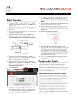
FIG. 4 Digital TV Configuration Manager
Command Buttons provide access to the main configuration pages
/