Page is loading ...

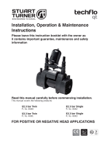
Booster Set (Vertical Twin) Installation,
Operation & Maintenance Instructions
Please leave this instruction booklet with the owner as
it contains important guarantee, maintenance and safety
information
Read this manual carefully before commencing installation.
This manual covers the following products:
ABB V150-45-2V-1
Pt. No. 46684
ABB V260-65-2V-1
Pt. No. 46687
ABB V150-60-2V-1
Pt. No. 46685
ABB V260-75-2V-1
Pt. No. 46688
ABB V150-75-2V-1
Pt. No. 46686
ABB V260-85-2V-1
Pt. No. 46689
(Subject to evidence of the required maintenance)
CE compliant product

- 2 -
PRODUCT DESCRIPTION
Twin electric motor driven centrifugal pump set complete with an automatic variable
speed duty/assist control system, incorporating pumps, VSD, transducer, pressure vessel
and electronic control.
APPLICATION
The Aquaboost Booster Set (vertical twin) range is designed for pressure boosting stored,
clean cold water into systems, where under gravity, no flow is available.
Inlet pressures to the pump and ambient temperatures must not exceed the
values given in the technical specifications.
z This pump set must not be used for any other application without
the written consent of Stuart Turner Ltd.
z This pump MUST NOT be connected directly to the mains water
supply.
z This appliance can be used by children aged from 8 years and
above and persons with reduced physical, sensory or mental
capabilities or lack of experience and knowledge if they have been
given supervision or instruction concerning use of the appliance
in a safe way and understand the hazards involved. Children shall
not play with the appliance. Cleaning and user maintenance shall
not be made by children without supervision.
z Children should be supervised to ensure that they do not play with
the appliance.
Please read installation details carefully as they are intended to ensure this
product provides long, trouble free service. Failure to install the unit in
accordance with the installation instructions will lead to invalidation of the
warranty.
STORAGE
If this product is not to be installed immediately on receipt, ensure that it is stored in a dry,
frost and vibration free location in its original packaging.
CONTENTS Page
Checklist ........................................................... 3
Important Facts - read before commencing installation ...................... 5
Location ........................................................... 7
Installation ......................................................... 9
Electrical ........................................................... 10
Control Programming ................................................. 13
Commissioning ...................................................... 20
Maintenance ........................................................ 22
Technical Specication ................................................ 23
Trouble Shooting .................................................... 25
Guarantee .......................................................... 27

- 3 -
CHECKLIST
Your product may vary slightly from the picture above.
Product Identification
Item Description Qty Item Description Qty
Booster set 1 Anti-vibration mounts 4
Pressure vessel (supplied loose) 1
A
C
B
IMPORTANT: With the pump removed from its packaging check for any
damage prior to installation. If any damage is found contact Stuart Turner Ltd
within 24 hours of receipt.
AB B V 150 45 2 V 1
No of pumps
Metres head (valve closed)
Flow rate (full flow, both pumps)
Variable speed
Aquaboost
Booster set
Vertical (pump orientation)
Single phase
Fig. 1
Discharge manifold
Removable cap
(ref: 2.25)
Suction manifold
Removable cap
(ref: 2.25)
Rating
plate
B
A
C

- 4 -
Cont ...
Product Performance
Performance curve indicates maximum performance, both pumps running.
0
1
2
3
4
5
6
7
8
9
0
10
20
30
40
50
60
70
80
90
100
0 50 100 150 200 250 300
Head (bar)
HEAD (metres)
FLOW (l/min)
Fig. 2

- 5 -
Cont ...
1 IMPORTANT FACTS: READ BEFORE COMMENCING PUMP INSTALLATION
A. Water storage capacity.
1.11 The cold water storage capacity must be sufficient to meet the flow rates
required by the pumped equipment and any other water using fittings and
appliances, which may be operated simultaneously.
1.12 Ensure the pump is primed as described in the priming section before starting,
damage to the shaft seal will result otherwise. See Section 6 - Commissioning.
B. Water temperature
This unit is designed to pump cold water only which should not exceed the following
values:
1.13 The maximum allowable water temperature is 23
o
C.
1.14 The minimum allowable water temperature is 4
o
C.
Note: Pump sets are available for handling greater temperatures, please contact us
for further information.
C. Pipework - General
1.15 Secure pipework: Ensure pipework to and from the booster set is
independently supported & clipped to prevent forces being transferred to inlet
and outlet branches of pump. Flexible hoses not supplied.
1.16 Flux: Solder joints must be completed and flux residues removed prior to pump
installation (flux damage will void any warranty).
1.17 Pipework design: Care should be taken in the design of pipework runs to
minimize the risk of air locks e.g. use drawn bends rather than 90
o
bends.
1.18 DO NOT install a non-return valve, or devices which contain non-
return valves, in the suction (inlet) pipework to the pump. The pump
must be free to vent to the supply tank at all times.
1.19 DO NOT connect this pump to the mains water supply.
D. Plumbing Installation Regulations
1.20 The plumbing installation must comply with the current water and building
regulations.
1.21 The plumbing installation must be installed by a qualified person.
1.22 The electrical installation must be carried out in accordance with the current
national electrical regulations.
1.23 The electrical installation must be installed by a qualified person.
E. Pressure vessel
1.24 Ensure the pressure vessel is installed correctly before operating the unit, to
avoid damage to the pumps/controls.
Do not attempt to dismantle the pressure vessel
Pressure vessel is charged at the factory see Section 7 - Maintenance for
details.

- 6 -
Cont ...
F. Lifting/Positioning
1.25 DO NOT lift the booster set by the pipework or by the control panel, the pressure
vessel is supplied lose for transport purposes, please ensure that the booster set
has been installed and connected to the suction and discharge pipework before
installing the pressure vessel. On no account should the pressure vessel be
used to “manouvre” the booster set into place. Care should be taken when
handling this product due to it’s weight.
1.26 This equipment must not be pressurised beyond maximum working pressure
(refer to technical specifications).

- 7 -
Cont ...
2 LOCATION - GENERAL
2.11 Access: For emergencies and maintenance the booster set must be
easily accessible.
2.12 Protection: The booster set must be located in a dry position, frost
free and protected from freezing. Avoid environments which have a
high ambient temperature, high humidity or excessive condensation.
Avoid dust, corrosive gas, explosive gas, inflammable gas, grinding-
fluid mist and salt damage, etc.
2.13 Ventilation: Ensure an adequate air flow to cool the pump. Separate
the pump from other appliances that generate heat.
2.14 Safety: The motor casing can become very hot under normal
operating conditions. Care must be taken to ensure it cannot be
touched during operation.
2.15 Water retention: Site the pump in a location where in the unlikely
event of a water leak, any spillage is contained or routed to avoid
electrics or areas sensitive to water damage.
2.16 Static inlet pressure: Care must be taken to ensure the booster set has
flooded suction from the cold water storage tank. Before deciding where to
locate the unit check to ensure the static inlet head between pump and the
bottom of the tank (Fig. 3) is at least 1 metre and does not exceed the max inlet
head of 10 metres. Inlet pressures in excess of 3 metres should be taken into
account when selecting the working pressure of the booster set, i.e. take the
static inlet pressure away from the required working pressure.
2.17 Booster set position: The unit must be mounted as close to the water source
as possible on a level surface, and if the plant-room has a chance of flooding it is
recommended that the unit is installed on a suitable plinth capable of taking total
working weight. If the optional anti-vibration bolt down mounts have been
purchased then fix these to the floor/plinth then fix the booster set to the anti-
vibration mounts.
2.18 Ensure that location of the unit allows adequate space to give reasonable access
to all parts to accommodate all service/commissioning, must be a minimum of
250 mm and easily see/operate the readout/controls.
2.19 Ambient temperature: The pump must be sited in a location where the
maximum ambient temperature does not exceed 40
o
C.
2.20 Pipework: For optimum performance:
V150 models have 1.1/2 “ BSP suction and discharge manifolds.
V260 models have 2 “ BSP suction and discharge manifolds.
All isolation valves should be full bore, non-restrictive type.
Flexible hoses are available separately, please contact us for further information.
Discharge pipework should only be reduced when entering the terminal fittings.
Note: Inlet pipework must always be greater than or equal to the outlet
pipework diameter.
2.21 Static outlet pressure: The static outlet head (Fig. 3) must also be within the
maximum requirement of 13 metres. The booster set should have been
selected to provide the required operating pressure at the highest outlet after
allowing for the static height of the highest fitting and the frictional losses in the
pipework. The minimum requirement at the highest outlet is usually 1 bar but
can be up to 3 bar depending on the type of fittings used.

- 8 -
Cont ...
2.22 Direction of flow: See Fig. 1 to identify the suction and discharge connections.
2.23 Isolating valves: Separate system isolating valves (non restrictive) must be
fitted to the suction and discharge of the pump set on the system side of the
flexible hoses.

- 9 -
Cont ...
3.11 The cold water supply: Must be a DEDICATED AIR FREE supply via a tank
connector and must be able to self vent. Flexible hoses are supplied with the
pump set and must be fitted between both suction and delivery manifolds and
the installation pipework.
Do not connect to the mains.
3.12 The suction and discharge caps can be installed on either end of the manifold to
facilitate ease of installation, please ensure these are water tight before switching
the unit on (see Fig. 1).
3.13 Pressure vessel: The pressure vessel is supplied loose, this must be fitted to
the connection on the discharge pipework. The connection is sealed with two
‘O’-rings within the end of the connection, ensure the ‘O’-rings are not damaged
during assembly. To fit the vessel tighten the running nut and open the isolation
valve.
3.14 DO NOT install the booster set where the control panel can be exposed to direct
sunlight or near sources of heat.
3.15 Non-return valves must not be fitted to suction or delivery as this may cause
incorrect operation and damage to the unit.
3 INSTALLATION
Fig. 3
Outlet to the
system
Static inlet pressure
Min. 1 m
Max. 10 m
Static outlet pressure
Max. 13 m
Fig. 4
Running nut
Turn lever to isolate
pressure vessel
Drain valve
Press button

- 10 -
Cont ...
4 ELECTRICAL
4.11 Regulations: The electrical installation must be carried out in
accordance with the current national electrical regulations and
installed by a qualified person.
4.12 Safety: In the interests of electrical safety a 30 mA residual current
device (R.C.D. not supplied) should be installed in the supply circuit.
Any RCD fitted must be suitable for operation with inverter drives,
i.e. Type A suitable for pulsation DC leakage current. This may be part
of a consumer unit or a separate unit.
4.13 Before starting work on the electrical supply ensure power supply is
isolated.
4.14 Install an emergency stop key separately from the isolator.
4.15 Earthing: This appliance must be permanently earthed via the supply cord,
which must be correctly connected to the earth point located in the terminal box.
The inverter should be protected separately against ground fault.
4.16 Additional earthing: Certain installations may require additional earthing
arrangements such as equipotential bonding. Reference should be made to the
relevant regulations concerning this subject to ensure compliance.
4.17 Connections: The pump set must be permanently connected to the mains
supply using a suitable sized cable using the double pole isolator fitted to the
pump set.
4.18 Wiring of connection unit:
WARNING: This appliance must be earthed.
Do not remove any cover of electrical components for at least 5 minutes to
allow total discharge of components after supply has been disconnected. When
making the electrical connections ensure all appropriate anti-static procedures
are taken.

- 11 -
Cont ...
4.19 Wiring Diagram:
Connect the pump set to the supply in accordance with the wiring diagram
shown below.
EN
E
L
VSD
1
L1 U
N V
PE PE
1
4
5
2
6
108
119
3
1
8
9
10
11
L1
N
U
V
PE PE
41
5
2
6
8 10
9
11
1
3
240v/1ph/50Hz/N/E
25 Amp Supply
63A/AC1
Panel Isolator
2.5 mm2
Tri-Rated
MS-HBC aM
P1
F
AquaBoost Controller
Pump
Pressure
Transducer
Float Switch
Closes to
Stop pump
Break Tank
(Optional)
Fault
Indication
Remote
(Optional)
MS-HBC aM
AquaBoost Controller
Pump
VSD2
Pressure
Transducer
Aquaboost Booster Set range
Fig. 5
Note:
This switch does not isolate
all connections to this panel.
Isolate elsewhere before
working on this equipment
Note:
1. This panel must be protected by a Type D
M.C.B or motor rated BS88 fuse, rating
see Section 3.21.
2. All protective devices are set to manual reset.
3. Panel wiring: All cables are Tri-rated
Mains=Phase Bm/Blk/Gry 2.5 mm
2
Motors=Phase Bm/Blk/Gry 1.5 mm
2
240 V a.c. Live=Brown/Neutral=Blue 0.5 mm
2
DC Live=Red/Neutral=Blue 0.5 mm
2
Volt free=White 0.5 mm
2
4. Earth Bonding=G/Y 4.0 mm
2

- 12 -
Cont ...
4.20 Fuses: Two fuses are fitted in the connection box fixed to the top of the pump
set, accessed via the clear front panel.
4.21 Pump controller:
z The connection of the alarms can distribute power even
when the frequency converter is turned off. Ensure that
there is no residual voltage on the terminals of the alarms.
z All the power terminals and other terminals must be
accessible after installation is completed. The maximum
output frequency must not exceed the design frequency of
the pump being controlled. Operating at a frequency
higher than the allowable frequency can cause higher
current absorption and damage to the device.
z If it is necessary to remove the frequency converter, remove
only the covers required in order to disconnect the
electrical cables. Take care not to damage the electronic
cards.
z Failure to comply with the safety regulations not only
causes risk to personal safety and damage to the
equipment, but also invalidates the warranty.
This pump set is controlled with two linked pump controllers, the controllers
allow the system pressure to be set on the digital display. The pump speed will
be varied by the controllers to maintain the set system pressure (Constant
pressure mode), if the set system pressure cannot be maintained with one pump
running, the second pump will automatically be started to increase the system
pressure to the set pressure (Duty/Assist).
Both controllers are electronically linked (Master and Slave) this allows the
pressure set on the master controller to be used for the slave controller,
simplifying the setting process. The master controller is the left hand unit and
will be confirmed when switching the unit on, the icon will appear
permanently on the master display panel.

- 13 -
Cont ...
5 CONTROL PROGRAMMING
Pump Start
Pump Stop
Access to programming menu/scroll up
Programming/confirm
Increase or scroll left
Decrease or scroll right
5.11 Screen format:
Fig. 6
Fig. 7
Auto mode Manual mode
Set-up mode activated
Alarm Sensor state Pump state
Duty-assist mode
Fixed speed modeConstant pressure mode
1
2
3

- 14 -
5.12 The display is divided into three key areas (see Fig. 7):
1 - System icons:
Auto mode
The system is operating in auto mode.
Manual mode
The system is operating in manual mode.
Set-up mode activated
It shows that the setup menu is activated. when an icon is blinking you
are modifying a parameter. You can confirm with enter.
Alarm
Indicates that a fault has occured, an error number will appear in the
display area. When in the set-up mode the alarm icon will not appear.
Sensor state
Indicates that the system is connected with the pressure transducer; if
it blinks there is a fault with the pressure transducer connected to that
controller.
Pump state
Indicates if the pump is running or in stand-by state.
Duty-assist mode
Indicates that the controls are in duty-assist mode. The 2 upper
symbols indicate if the pumps are running or in stand-by mode. The
lower symbol confirms if the pump is the master (permanantly alight) or
slave (blinking).
Constant pressure mode
The system keeps the pressure constant when the flow rate of water
varies dependant on demand.
Fixed speed mode
In this mode the controller operates the pump at a fixed speed that the
user can choose according to need (not used).
2 - Display area:
Is composed of an incremental bar proportional with the displayed value and its
unit of measure. The display is backlit, the light will be turned off after
20 seconds of system inactivity.
3 - Operating icons:

- 15 -
Cont ...
5.13 Low water cutout:
To protect the booster set from running out of water a float switch can be fitted
into the supply tank and should be wired into terminals 8 and 9 of both
controllers (see Fig. 8).
5.14 Remote alarm connection:
Using terminals 10 and 11, a remote alarm can be connected to both controllers
(see Fig. 9).
The remote alarm can be used to signal:
- error on the frequency converter (nO)
- the frequency converter is running (nC).
Operating limits: 250 V a.c., 450 mA maximum resistive
current.
Fig. 8
Electrical connection
Fig. 9
Electrical connection

- 16 -
5.15 Dry running protection:
The controllers are equipped with two methods of dry running protection:-
1) The system pressure is monitored by the controller, if the system pressure
drops below a pre-set level (SP07) for longer than a pre-set time (AP05) the
pumps will be stopped.
2) If an external float or level switch is to be connected to the controllers (see
Page 14, Fig. 8) the controller will stop the pumps when the switch is
activated, when the switch is re-set by the rising water level, the pumps will
re-start automatically after a pre-set time delay (AP19)
For entering the programming mode see 5.24.
5.16 Parameters:
On the controller the following information is displayed:
- Pump status
- Programming
- Alarms
5.17 Pump status:
The following controller operating conditions can be displayed:-
1) Frequency of the electrical supply to the pump (this will be different on each
controller, between 30 & 50 Hz)
2) System pressure in bar
3) Current drawn (amps) by the pump that is connected to the controller (this
will be different on each controller)
Starting from the basic display by pushing of the directional arrow (plus) or
(minus) these parameters are displayed for example:
Fig. 10

- 17 -
Cont ...
5.18 Programming:
To display the programming parameters, select (menu) and the following will
be displayed progressively:
UP - User settings: these are the basic settings that the user can change.
AP - Advanced settings: these settings are available only to qualified
personnel. Password entry is required (contact PumpAssist for
assistance).
SA - Technical assistance settings: these are the advanced parameters, only
technical assistance personnel are allowed to access this menu.
Password entry is required (contact PumpAssist for assistance).
MAn - Fixed speed mode activation: this allows activation of the fixed speed
mode and the working frequency. Only qualified personnel are allowed to
access this menu. Password entry is required (contact PumpAssist for
assistance).
AE - Advanced parameters: this allows display of the secondary parameters
which can be useful for system diagnostics.
Example: AE01 software release
AE02 supply voltage (V)
AE03 last 5 faults
5.19 Supply voltage display:
By pushing the button (menu) the UP parameter appears. Select the AE
parameter by pushing the (plus) up to arrive at the correct parameter
, confirm with (enter).
Select the parameter by pushing the button (plus) and confirm with
(enter).
Supply voltage is displayed.
5.20 UP - User settings
UP01-04 are factory set and should not be changed.
No Description Factory
settings
Modifications Note
UP01
restart mode power failure
[rA = automatic; rM = manual]
rA
UP02 Nominal pump current (A) 0.1
UP03 Nominal pump frequency (HZ) 50
UP04
Direction of rotation
[--- = std rotation; E--- = inverted rotation]
---
UP05 Set point pressure (bar) 1.5
E
E

- 18 -
Cont ...
5.21 AP - Advance settings
To enter password is required contact PumpAssist for assistance on
+44 (0) 800 31 969 80.
No Description Factory
settings
Modifications Note
AP01
Pressure transducer set-up
[sensor full-scale]
(bar) 10
AP02 Ramp down (s) 3
AP03
Ramp-up
(fixed value for MM)
(s)
2MT
0 MM
AP04 Time before stop (s) 30
AP05 Dry run pressure (s) 10
AP06 First dry run time 60
AP07 Dry run pressure 1.5
AP08
System dynamic
[1 = fast dynamic; 5 = slow dynamic]
3
AP09
Duty-assist mode
[oFF; UU = duty-assist mode with double inverter;
UF= duty-assist mode with an inverter]
oFF
AP010
Master/Slave setting
MAS = master; SLA = slave
SLA
AP011 Reset to factory set-up
AP012
Digital input activation
[0 = oFF; 1 = no; 2 - nC]
1
AP013
Digital output activation
[0 = oFF; 1 = on; 2 = no; 3 - nC}
0
AP014 Restart fall pressure set-up (bar)
AP015 Pump address SLA1
AP016 Duty-assist mode start fall pressure set-up (bar) 0.3
AP017 Duty-assist mode restart delay (s) 10
AP018 Duty-assist mode fall pressure limit set-up (bar) 0.6
AP019
Digital input delay time
[float switch delay time]
(s) 30

- 19 -
Cont ...
5.22 SA - Technical assistance settings
To enter password is required contact PumpAssist for assistance on
+44 (0) 800 31 969 80.
No Description Factory
settings
Modifications Note
SA01
SA02
SA03 Pressure PID (Proportional gain) 2.8
SA04 Pressure PID (Integral time constant) 5.5
SA05 Pressure PID (Derivative time constant) 5.0
SA06 Min. run frequency (Hz) 30
SA07 Max. frequency (Hz) 60
SA08 Set point pressure step up (bar) 0.3
SA09 Pressure step up time (s) 3
SA010 Pressure step up ramp (bar/s) 0.3
SA011 Set point control ramp (bar/s) 0.4
SA012 Carrier frequency 7010
SA013 Singlephase starting requency (Hz) 80
SA014 Singlephase starting voltage (V) 195
SA015 Nominal voltage (V) 220
5.23 MAn - Fixed speed mode activation
To enter password is required contact PumpAssist for assistance on
+44 (0) 800 31 969 80.
No Description Factory
settings
Modifications Note
MAn1 Fixed speed mode activation oFF
MAn2 Working frequency [MAn2 ≤ UP03] (Hz) 45
5.24 Programming
To enter programming:-
1) Select (menu). Use the buttons (plus) or (minus) to select the
parameter to be modified and confirm with (enter).
2) Use the buttons (plus) or (minus) to select the parameter to be
modified and confirm with (enter).
3) Using buttons (plus) or (minus) increase or decrease the value. From
this moment the set-up icon start blinking until the value is confirmed
with (enter).
4) To exit the program, push (menu) until when you arrive back on the initial
display screen. The set-up icon will disappear once the action is
complete.

- 20 -
Cont ...
6 COMMISSIONING
6.11 Isolate the booster set before pressure testing the system.
Over pressure could damage the pressure transducer and
diaphragm in the pressure vessel.
6.12 Each booster set is factory set to the required perameters
as per the agreed specification and per the operating
perameters set out elsewhere in this manual. We strongly
recommend that commissioning and service work is carried
out by the manufacturer’s personnel or appointed agents.
Please contact our technical sales department for information
on our commissioning and service contract packages.
6.13 System Flushing
The pipework system should be flushed out prior to the pump being
connected to ensure any contaminants/chemical residues and foreign
bodies are removed from elsewhere in the system.
6.14 Water supply: Always ensure that water storage capacity is adequate to meet
the demand. Ensure the pump chambers are full of water before starting the
unit. Failure to do this could result in seal damage. To ensure dry running does
not occur the pumps must be primed as described in priming section below.
Do not run pump(s) dry.
6.15 Priming:
Never operate the unit with inlet and/or outlet isolating valves
in the closed position. Damage will occur!
The pump’s must be primed (filled with
water) before starting.
(a) Turn on the service valves and vent/
prime pump head.
(a) Loosen priming plug on each pump
and allow an even flow of water this
may take a few seconds.
(b) Re-seal draining plug, nipping tight.
The pump is now ready to start.
6.16 Starting:
a) Ensure the pumps are vented and the water supply turned on.
b) Turn on the electrical supply at the isolator switch in the connection box.
c) The pump set will automatically start if the rA option (default setting) is selected.
If the pump set does not start press button and the controller will start the
pumps.
Fig. 11
Priming/
vent
Plug
Drain
Plug
Priming/
vent
Plug
/