Page is loading ...

mainsboost
Read this manual carefully before commencing installation.
This manual covers all Mainsboost vessels for vertical and horizontal and units.
Mainsboost Installation, Operation &
Maintenance Instructions
Please leave this instruction booklet with the home owner as it contains
important guarantee, maintenance and safety information
CE compliant product

- 2 -
PRODUCT DESCRIPTION
Mainsboost consists of one key assembly, the Mainsboost vessel complete with upstream
line-in kit.
APPLICATION
Mainsboost is designed to offer stored clean, potable cold water under pressure for all
domestic or small commercial applications where mains water is insufficient to offer
consistent and reliable water services.
Installation parameters must not exceed the values given in the technical
specifications.
zMainsboost system must not be used for any
other application without the written consent of
Stuart Turner Limited.
zThis appliance can be used by children aged
from 8 years and above and persons with reduced
physical, sensory or mental capabilities or lack of
experience and knowledge if they have been given
supervision or instruction concerning use of the
appliance in a safe way and understand the
hazards involved. Children shall not play with the
appliance. Cleaning and user maintenance shall
not be made by children without supervision.
zChildren should be supervised to ensure that they
do not play with the appliance.
Please read installation details carefully as they are intended to ensure this
product provides long, trouble free service. Failure to install the unit in
accordance with the installation instructions will lead to invalidation of the
warranty. These instructions must be left with the product.
STORAGE
If this product is not to be installed immediately on receipt, ensure that it is stored in a dry,
frost and vibration free location in its original packaging.
CONTENTS Page
Checklist ................................................................3
Introduction .............................................................4
Important Facts - read before commencing installation ...........................5
Location ................................................................6
Terminology .............................................................7
Conguration ............................................................8
Installation ..............................................................10
Commissioning ...........................................................14
Technical Specication .....................................................15
Trouble Shooting .........................................................16
Guarantee ...............................................................17

- 3 -
Cont ...
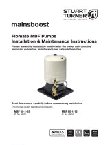
CHECKLIST
Item Description Qty Item Description Qty
Package
1
1 ¼ “ BSP pressure gauge 2 Package
21 Mainsboost vessel 1
2 Lever isolating ball valve 1
3Pressure vessel connector
fitting 1Package
31 Cradle 2
46 bar pressure regulating
valve 1
5 ¼ x ½ “ BSP Brass bush 1
6 Y pattern inline strainer 1
7 Double check valve 1
8 1¼ “ BSP Pressure gauge 1
Your product may vary slightly from the picture above.
IMPORTANT: Your Mainsboost water performance system will be delivered
in a minimum of two boxes on one pallet. Please check the contents within
24 hours of receipt and if any component is damaged, please contact Stuart
Turner Ltd immediately.
Package 2
Mainsboost vessel
Fig. 2
1
Package 1
Upstream line-in kit
Fig. 1
61
4
8
5
2
7
3
Package 3
Cradle
(only applicable for horizontal installations with
MB 200SH or MB 250SH models)
Fig. 3

- 4 -
Cont ...
1 INTRODUCTION
1.1 Congratulations on buying a Mainsboost system, designed to offer consistent
and reliable water services throughout the property and the only system available
that is patent protected No. GB2349908.
1.2 Patents, Trademarks & Trade Names:
‘Mainsboost’ ‘Mainsboost Plus™’ and ‘Mainsboost Charger’ are
registered Trademarks of Stuart Turner Ltd.
The use of this system is patent protected and the Mainsboost vessel cannot
be mixed with other accumulator systems without prior approval from
Stuart Turner Ltd.
The Mainsboost vessels have special characteristics and the use of other
vessels in this application could prove to be detrimental to the design and
performance of the system and the patent.
Stuart Turner Ltd will treat any infringement of the patent very seriously and
therefore recommend that any questions regarding application be brought to the
company for consideration.
1.3 How the Mainsboost System works:
The Mainsboost vessel stores water from the rising main in a sealed water
chamber, separated from the air space by a rubber diaphragm and pressurised
to an optimum setting. When water is drawn off by downstream services, the
water from the mains is supplemented by the water from the Mainsboost unit to
provide a balanced supply at consistent pressure to downstream services.

- 5 -
Cont ...
2 IMPORTANT FACTS READ BEFORE COMMENCING INSTALLATION
A. Water temperature
This unit is designed for cold water applications only which should not exceed the
following values:
2.11 The maximum allowable water temperature is 35 oC.
2.12 The minimum allowable water temperature is 4 oC.
B. Pipework - General
2.13 Secure pipework: Ensure pipework to and from the Mainsboost is
independently supported & clipped to prevent forces being transferred.
2.14 Flux: Solder joints must be completed and flux residues removed prior to
completing the installation (flux damage will void any warranty).
2.15 Pipework design: Care should be taken in the design of pipework runs to
minimize the risk of air locks e.g. use drawn bends rather than 90o bends.
C. Plumbing Installation Regulations
2.16 The plumbing installation must comply with the current water and building
regulations.
2.17 The plumbing installation must be installed by a qualified person.
D. Mainsboost vessel
2.18 Ensure the Mainsboost vessel is installed correctly before operating the unit, to
avoid damage.
Do not attempt to dismantle the Mainsboost vessel
The Mainsboost vessel is pressurised to a pre-set level at the factory see
Section 7.11 - Commissioning for details.

- 6 -
Cont ...
3 LOCATION - GENERAL
3.11 Access: For emergencies and maintenance the Mainsboost must be
easily accessible.
3.12 Protection: The system must be located in a dry position, and
protected from freezing. Avoid environments which have a high
ambient temperature, high humidity or excessive condensation
and salt damage, etc.
3.13 Incoming mains water pressure: The incoming water pressure of at least
1.5 bar is required and should not exceed 5 bar.
3.14 Ensure that location of the unit allows adequate space to give reasonable access
to all parts to accommodate service/commissioning.
3.15 Pipework: Pipework should be sized to ensure optimum performance of the
system.
3.16 Direction of flow: See Fig. 4 to identify the suction and discharge connections.

- 7 -
Cont ...
4 TERMINOLOGY
4.11 System Designation:
It is important to understand what upstream and downstream refers to before
starting the installation.
4.12 Upstream
The term ‘Upstream’ refers to the system configuration from the consumer’s
stopcock to the point where the supply reaches the inlet port of the Mainsboost
vessel.
4.13 Downstream
The term ‘Downstream’ refers to the system configuration from the outlet tapping
on the Mainsboos vessel, along the distribution header (if configured in this way)
and into the distribution pipework and outlets. This includes hot and cold
services where both are present (see Fig. 4).
Fig. 4 System designation
Direction of flow

- 8 -
Cont ...
5 CONFIGURATION
5.11 Mainsboost is a very flexible solution, offering a patent protected packaged
system to suit any type or size of building no matter how large or small the
demand is. The following illustrations depict just some of the most typical
installations.
5.12 Single occupancy application:
Use of Mainsboost in a house
offers water on demand whilst
giving maximum flexibility. As
can be seen the upstream
line-in kit has to be fitted on to
the rising main but the vessels
can be fitted wherever there is a
space, for example; utility,
kitchen, upstairs cupboard or
loft, providing adequate
provisions are taken for the
weight, frost protection etc (see
Fig 5). Where height restrictions
exist the MB 200SH and
MB 250SH Mainsboost units
can be supplied suitable for
horizontal installation.
5.13 Multiple occupancy application:
Often affected by poor water
supplies Mainsboost offers the
perfect solution. For multiple
occupancy buildings again the
upstream line-in kit is located
next to the rising main and sized
to meet the demand of the
entire building. Each apartment
then has its own vessel located
within the property, sized to meet
the apartments own demand
(see Fig. 6).
Fig. 6
Fig. 5

- 9 -
Cont ...
5.14 High demand single occupancy application:
Where single properties have a much higher demand, it may be necessary to
use additional Mainsboost vessels connected in parallel to ensure sufficient
water is on tap to meet the much higher demand. Fig. 7 shows all vessels being
located in the same place.
5.15 Water softener:
Note: If a water softener is to be fitted it must be located between the upstream
line-in kit and the vessel. If high pressure is also required to the drinking tap fit a
Stuart Water Conditioner, available from Stuart Turner, rather than a water
softener.
Fig. 7
Fig. 8
Water softener

- 10 -
Cont ...
6 INSTALLATION
Step 1:
Remove the Mainsboost vessel from its packaging and check to ensure it is not
damaged.
zWARNING: depending on cylinder size this may require two
people to complete safely.
zEnsure the floor is sufficiently strong enough to take the total
weight of the unit when full of water (see Technical
Specification section). Take care when manoeuvring the unit
so as not to damage it.
6.11 Vertically mounted Mainsboost vessels
a) Carefully turn the vessel on its side using the discarded packaging to protect
it.
b) Once on its side screw the Mainsboost vessel connector (item 3) provided in
the upsteam line-in kit into the tank elbow at the base using suitable thread
seal such as PTFE tape or liquid thread lock (see Fig. 9).
c) Cut a piece of 28 mm dia. copper pipe to the following minimum length,
ensuring clearance of the base.
Pipe length:
MB 100SV = 210 mm MB 200SV = 270 mm MB 300SV = 270 mm
MB 130SV = 210 mm MB 250SV = 270 mm MB 450SV = 340 mm
Then re-erect the cylinder.
d) Fit the isolating valve provided to the tail now protruding from the base of the
vessel.
e) The vessel assembly should then be positioned and checked to ensure
there is sufficient space to install the upstream line-in kit between the
stopcock and pressure vessel inlet. Refer to the chart (Fig. 17) as a guide.
Fig. 9
item 3
item 2

- 11 -
Cont ...
f) Fix the Mainsboost vessel securely to the floor using appropriately selected
and sized fixings.
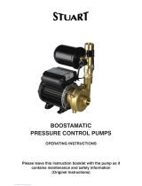
6.12 Horizontally mounted vessels
a) Fix the two cradles in place where the unit is to be located in line with each
other per chart shown below.
b) Position the cylinder centrally on the cradles with the outlet elbow facing
upwards.
Dimension between hole centres
Tank size A
200 litre 570 mm
250 litre 740 mm
Fig. 10
Fig. 11
Fig. 12
A
Vertically mounted
vessels

- 12 -
d) With the vessel on its side screw the Mainsboost vessel connector (item 3)
provided in the upsteam line-in kit, into the tank elbow using suitable thread
seal such as PTFE tape or liquid thread lock (see Fig. 16).
e Cut a piece of 28 mm dia. copper pipe to the following minimum length,
ensuring clearance of the base.
Pipe length:
MB 100SV = 210 mm MB 200SV = 270 mm MB 300SV = 270 mm
MB 130SV = 210 mm MB 250SV = 270 mm MB 450SV = 340 mm
f) Fit the isolating valve provided to the tail.
c) Remove the plastic skirt by rotating anti-clockwise to unclip and discard.
Please note: Horizontal mounting is available for the steel MB 200 SH
and MB 250 SH vessels only.
Note: Do not forget if a water softener is to be installed this has to be
included in this pipe run, and additional space must be allocated for
this.
Do not fit smaller pipework than the upstream line-in kit accepts as
this will impair performance.
Fig. 13
Step 1: twist Step 2: unclip
Step 3: pull off
Fig. 14
Fig. 15
Fig. 16
item 3
item 2

- 13 -
Cont ...
Pipe
Size
Minimum pipe length required to install the
upstream line-in kit (mm) (A)
22 mm 480 mm
28 mm 580 mm
35 mm 630 mm
40 mm 735 mm
54 mm 820 mm
Step 2:
Upstream line-in kit
The upstream line-in kit includes:
1 - inline strainer
2 - pressure gauge (upstream)
3 - double check valve
4 - pressure reducing valve
5 - pressure gauge (fitted to pressure reducing valve)
6 - MainsBoost vessel connector (see step 1)
The above components must be installed in the correct order to ensure safe and
satisfactory system operation.
Completed installation
Fig. 17
5
4
3
2 (T-piece not supplied)
1
Inlet
Outlet
A

- 14 -
Cont ...
7 COMMISSIONING
7.11 Check vessel pre-charge pressure:
It is important to have the correct pre-charge pressure in the vessel for your site
conditions to optimise performance.
Checking and adjustment to the vessel pre-charge air pressure can only be
carried out when the vessel is empty (contains no water).
7.12 Check mains dynamic pressure:
zOpen outlets and check pressure gauge after ‘Y’ strainer - for dynamic
mains pressure and note it.
zTurn stopcock off and leave outlet taps open.
7.13 Check the chart below for the correct vessel pressure against the dynamic mains
pressure recorded.
7.14 On completion of the installation, follow the commissioning process below.
zLeave all outlet valves closed.
zTurn on stopcock and open inlet ballvalve, both pressure gauges on inlet and
PRV will start to show movement as the mains pressure fills the system.
zCheck for leaks on all joints made.
zThe incoming mains pressure will start to fill the vessel with water.
The time taken to fill the vessel will vary depending on the vessel size and mains
water pressure.
Mains pressure
Set vessel
pre-charge pressure
to
Differential Set PRV maximum
setting to
bar bar bar bar
1.5 0.55 1.0 2.0
2.0 0.55 1.5 2.5
2.5** 1.0 1.5 3.0*
3.0 1.5 1.5 3.5
3.5 2.0 1.5 4.0
4.0 2.5 1.5 4.5
*Adjust pressure regulating valve down to these settings where possible.
**Recommended setting.
Using a pressure gauge check the vessel and adjust to suit through the schrader
valve.
Warning: Note PRV setting must not exceed 5.0 bar.
Fig. 18

- 15 -
Cont ...
8 TECHNICAL SPECIFICATION
Mainsboost Vessel
General
Construction Mild steel
Membrane Butyl rubber
WRAS approval 1611336
System patent no. 2349908
Guarantee 5 years
Performance
Maximum head (closed valve) 4.3 bar
Maximum working pressure* 600 kPa (6 bar)
Maximum ambient air temperature 40 oC
Min / Max water temperature Min 4 oC / Max 35 oC
Model
Vessel
capacity
(litres)*
Dimensions
(mm)
Weight
empty (Kg)
Dry
Total weight
(Kg)
Maximum
weight (Kg)
Connectors
supplied
Steel
vessels
MB 100SV 55 890 x 410 19 69 119 1 " BSP x 28 mm
MB 130SV 71 1100 x 410 23 88 153 1 " BSP x 28 mm
MB 200SV/SH 110 1030 X 535 34 119 204 1¼ " BSP x 28 mm
MB 250SV/SH 132 1210 X 535 37 157 277 1¼ " BSP x 28 mm
MB 300SV 174 1500 X 535 46 211 376 1¼ " BSP x 28 mm
MB 450SV 248 1530 X 660 70 295 520 1¼ " BSP x 28 mm
MB 600SV 330 1859 X 740 128 458 728 1½ " BSP x 35 mm
MB 800SV 440 2325 X 740 176 616 976 1½ “ BSP x 35 mm
MB 1000SV 550 2604 X 740 214 764 1214 1½ “ BSP x 35 mm
*working pressure
Stuart Turner reserve the right to amend the specification in line with its policy of
continuous development of its products.
*Note: The maximum pressure that can be applied to the pump under any installation
conditions.

- 16 -
Cont ...
9 TROUBLE SHOOTING GUIDE
Symptoms Probable Cause Recommended Action
Poor flow. ISO valve not opened on
pressure vessel.
Check valve is fully open.
Poor pressure. Mains pressure dropped. Check pressure gauge on supply (2) Fig. 17.
If below 1.5 bar at peak times, recommend use of
Mainsboost Plus pump.
Filter blocked. Isolate system and clean out strainer.
PRV set incorrectly. Check PRV ga ould read between 1.5 and 3.0 bar, adjust to
suit.
Note: Pressure gauge (2) reading has to exceed desired
pressure on (4).
System works but runs out of
water.
Insufficient vessel capacity. Call Stuart Turner on +44 (0) 800 31 969 80

- 17 -
10 GUARANTEE
Congratulations on purchasing a Stuart Turner Mainsboost system.
We are confident this product will give you many years of trouble free service as all our
products are manufactured to the very highest standard.
The Mainsboost benefits from a five year guarantee.
Within the guarantee period we will repair, free of charge, any defects in the
Mainsboost resulting from faults in material or workmanship, repairing or exchanging the
part affected or whole unit as we may reasonably decide.
Not covered by this guarantee: Damage arising from incorrect installation, improper use,
unauthorised repair, normal wear and tear and defects which have a negligible effect on
the value or operation of the unit.
Reasonable evidence must be supplied that the product has been purchased within the
guarantee term prior to the date of claim (such as proof of purchase or the product serial
number).
This guarantee is in addition to your statutory rights as a consumer. If you are in any
doubt as to these rights, please contact your local Trading Standards Department.
In the event of a claim please telephone ‘PumpAssist’ customer support.
+44 (0) 800 31 969 80
You should obtain appropriate insurance cover for any loss or damage which is not covered
by Stuart Turner Ltd in this provision.
Please record here for your records.
TYPE NO. SERIAL NO. DATE PURCHASED


DECLARATION OF CONFORMITY
2006/42/EC
BS EN ISO 12100-1, BS EN ISO 12100-2
2006/95/EC
BS EN 60335-1
2014/29/EU
IT IS HEREBY CERTIFIED THAT THE MAINSBOOST SYSTEM AS SERIAL NUMBER BELOW,
COMPLIES WITH THE ESSENTIAL REQUIREMENTS OF THE ABOVE E.E.C. DIRECTIVES.
RESPONSIBLE PERSON
AND MANUFACTURER STUART TURNER LIMITED
HENLEY-ON-THAMES, OXFORDSHIRE
RG9 2AD ENGLAND.
Signed ................................................ Technical Director
Stuart Turner are an approved company to BS EN ISO 9001:2000
Stuart Turner Ltd, Henley-on-Thames, Oxfordshire RG9 2AD ENGLAND
Tel: +44 (0) 1491 572655, Fax: +44 (0) 1491 573704
[email protected] www.stuart-turner.co.uk
Issue No. 4217/1-01 Pt. No. 20531
/