DFI EC531-SD/EC532-SD Owner's manual
- Category
- Motherboards
- Type
- Owner's manual
This manual is also suitable for

www.d.com
1
EC531/532-SD
User’s Manual
A-457-M-2008

www.d.com
2
Copyright
This publication contains information that is protected by copyright. No part of it may be re-
produced in any form or by any means or used to make any transformation/adaptation without
the prior written permission from the copyright holders.
This publication is provided for informational purposes only. The manufacturer makes no
representations or warranties with respect to the contents or use of this manual and specifi-
cally disclaims any express or implied warranties of merchantability or fitness for any particular
purpose. The user will assume the entire risk of the use or the results of the use of this docu-
ment. Further, the manufacturer reserves the right to revise this publication and make changes
to its contents at any time, without obligation to notify any person or entity of such revisions
or changes.
Changes after the publication’s first release will be based on the product’s revision. The website
will always provide the most updated information.
© 2019. All Rights Reserved.
Trademarks
Product names or trademarks appearing in this manual are for identification purpose only and
are the properties of the respective owners.
FCC and DOC Statement on Class A
This equipment has been tested and found to comply with the limits for a Class A digital
device, pursuant to Part 15 of the FCC rules. These limits are designed to provide reason-
able protection against harmful interference when the equipment is operated in a residential
installation. This equipment generates, uses and can radiate radio frequency energy and, if not
installed and used in accordance with the instruction manual, may cause harmful interference
to radio communications. However, there is no guarantee that interference will not occur in a
particular installation. If this equipment does cause harmful interference to radio or television
reception, which can be determined by turning the equipment off and on, the user is encour-
aged to try to correct the interference by one or more of the following measures:
• Reorient or relocate the receiving antenna.
• Increase the separation between the equipment and the receiver.
• Connect the equipment into an outlet on a circuit different from that to which the receiver
is connected.
• Consult the dealer or an experienced radio TV technician for help.
Notice:
1. The changes or modifications not expressly approved by the party responsible for compli-
ance could void the user’s authority to operate the equipment.
2. Shielded interface cables must be used in order to comply with the emission limits.

www.d.com
3
Copyright .............................................................2
Trademarks ..........................................................2
FCC and DOC Statement on Class A ..................... 2
About this Manual ................................................ 4
Warranty ............................................................4
Static Electricity Precautions ................................. 4
Safety Measures...................................................4
Safety Precautions ...............................................5
About the Package ............................................... 5
Chapter 1 -Introduction ........................................ 6
Overview .................................................................................6
Key Features ...........................................................................6
Specifications ...........................................................................7
Getting to Know the EC531/EC532-SD .....................................8
Mechanical Dimensions ............................................................9
Chapter 2 - Getting Started ..................................10
Chapter 3 - Installing the Devices .........................11
Removing the Chassis Cover ...................................................12
Installing a SODIMM .............................................................. 12
Installing a Mini PCIe or mSATA Card .....................................13
Installing a PCI or PCIe Expansion Card ................................. 14
Installing a CPU ..................................................................... 15
Chapter 4 - Jumper Settings .................................17
Clear CMOS Data ................................................................... 17
Auto Power-on Select ............................................................. 17
COM1/COM2 RS232 Power Select (maindboard) ..................... 18
COM4/COM5 RS232 Power Select (daughter board) ............... 18
COM1 /COM2 /COM3 RS232/422/485 Select (mainboard) ...... 19
COM4 /COM5 /COM6 RS232/422/485 Select (daughter board) 20
Chapter 5 - Ports and Connectors ......................... 21
Front Panel I/O Ports .............................................................21
USB Ports (mainboard) ............................................................................... 21
COM (Serial) Ports (mainboard) ................................................................... 22
9~36V DC-in .............................................................................................. 22
RJ45 LAN Ports ........................................................................................... 23
Display Interfaces ....................................................................................... 23
I/O Connectors ...................................................................... 24
Parallel Connector ....................................................................................... 24
SATA (Serial ATA) Connectors ...................................................................... 24
SATA (Serial ATA) Power Connectors ............................................................ 25
SMBus Connector ...................................................................................... 25
Cooling Fan Connectors............................................................................... 26
Digital I/O Connector (mainboard) ............................................................... 26
Audio Connector ......................................................................................... 27
Front Panel Connector ............................................................................... 27
S/PDIF Connector ....................................................................................... 28
LPC Connector ............................................................................................ 28
Expansion Slots .......................................................................................... 29
12V DC-out ................................................................................................ 30
Digital I/O Connector (daughter board) ....................................................... 31
COM (Serial) Ports (daughter board) .......................................................... 31
USB Ports (daughter board) ........................................................................ 32
Chapter 6 - Mounting Options .............................. 33
Chapter 7 - BIOS Setup ....................................... 34
Main .......................................................................................................... 35
Advanced .................................................................................................. 35
Security ...................................................................................................... 43
Boot........................................................................................................... 44
Exit ............................................................................................................ 46
Chapter 8 - Supported Software ...........................48
Chapter 9 - RAID ................................................64
Chapter 10 - Intel AMT Settings .......................... 68

www.d.com
4
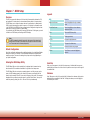
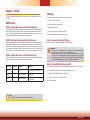
About this Manual
An electronic file of this manual can be obtained from the DFI website at www.dfi.com.
To download the user’s manual from our website, please go to “Support” > “Download Center.”
On the Download Center page, select your product or type the model name and click “Search”
to find all technical documents including the user’s manual for a specific product.
Warranty
1. Warranty does not cover damages or failures that arised from misuse of the product,
inability to use the product, unauthorized replacement or alteration of components and
product specifications.
2. The warranty is void if the product has been subjected to physical abuse, improper instal-
lation, modification, accidents or unauthorized repair of the product.
3. Unless otherwise instructed in this user’s manual, the user may not, under any circum-
stances, attempt to perform service, adjustments or repairs on the product, whether in or
out of warranty. It must be returned to the purchase point, factory or authorized service
agency for all such work.
4. We will not be liable for any indirect, special, incidental or damages to the product that
has been modified or altered.
Static Electricity Precautions
It is quite easy to inadvertently damage your PC, system board, components or devices even
before installing them in your system unit. Static electrical discharge can damage computer
components without causing any signs of physical damage. You must take extra care in han-
dling them to ensure against electrostatic build-up.
1. To prevent electrostatic build-up, leave the system board in its anti-static bag until you are
ready to install it.
2. Wear an antistatic wrist strap.
3. Do all preparation work on a static-free surface.
4. Hold the device only by its edges. Be careful not to touch any of the components, contacts
or connections.
5. Avoid touching the pins or contacts on all modules and connectors. Hold modules or con
nectors by their ends.
Safety Measures
To avoid damage to the system:
• Use the correct AC input voltage range.
To reduce the risk of electric shock:
• Unplug the power cord before removing the system chassis cover for installation or
servicing. After installation or servicing, cover the system chassis before plugging the power
cord.
Battery:
• Danger of explosion if battery incorrectly replaced.
• Replace only with the same or equivalent type recommend by the manufacturer.
• Dispose of used batteries according to local ordinance.
Important:
Electrostatic discharge (ESD) can damage your processor, disk drive and other com-
ponents. Perform the upgrade instruction procedures described at an ESD worksta-
tion only. If such a station is not available, you can provide some ESD protection by
wearing an antistatic wrist strap and attaching it to a metal part of the system chas-
sis. If a wrist strap is unavailable, establish and maintain contact with the system
chassis throughout any procedures requiring ESD protection.

www.d.com
5
About the Package
The package contains the following items. If any of these items are missing or damaged,
please contact your dealer or sales representative for assistance.
• 1 EC531/EC532-SD system unit
• 1 Quick Installation Guide
Optional Items
• Wall Mount kit
• Power Cord
• Power Adapter (100W/120W/160W)
The board and accessories in the package may not come similar to the information listed
above. This may differ in accordance to the sales region or models in which it was sold. For
more information about the standard package in your region, please contact your dealer or
sales representative.
Safety Precautions
• Use the correct DC input voltage range.
• Unplug the power cord before removing the system chassis cover for installation or servic-
ing. After installation or servicing, cover the system chassis before plugging the power cord.
• Danger of explosion if battery incorrectly replaced.
• Replace only with the same or equivalent type recommend by the manufacturer.
• Dispose of used batteries according to local ordinance.
• Keep this system away from humidity.
• Place the system on a stable surface. Dropping it or letting it fall may cause damage.
• The openings on the system are for air ventilation to protect the system from overheating.
DO NOT COVER THE OPENINGS.
• Place the power cord in such a way that it will not be stepped on. Do not place anything on
top of the power cord. Use a power cord that has been approved for use with the system
and that it matches the voltage and current marked on the system’s electrical range label.
• If the system will not be used for a long time, disconnect it from the power source to avoid
damage by transient overvoltage.
• If one of the following occurs, consult a service personnel:
- The power cord or plug is damaged.
- Liquid has penetrated the system.
- The system has been exposed to moisture.
- The system is not working properly.
- The system dropped or is damaged.
- The system has obvious signs of breakage.
• The unit uses a three-wire ground cable which is equipped with a third pin to ground the
unit and prevent electric shock. Do not defeat the purpose of this pin. If your outlet does
not support this kind of plug, contact your electrician to replace the outlet.
• Disconnect the system from the DC outlet before cleaning. Use a damp cloth. Do not use
liquid or spray detergents for cleaning.

www.d.com
6
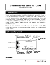
Chapter 1 -Introduction
Chapter 1
Overview
Key Features
Model Name EC531/EC532-SD
Processor 6th Generation Intel
®
Core
TM
processors
Chipset Intel
®
H110 Chipset or Intel
®
Q170 Chipset
LAN 2 LAN ports
COM 6 COM ports
Display VGA
DVI (DVI-D signal)
HDMI or DP (DP available upon request)
USB 8 USB 3.0 Type A ports
Power 9~36V DC-in
*HDMI is only available for the Intel
®
Q170 Chipset.
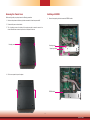
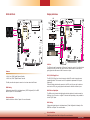
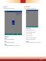
Front Panel

www.d.com
7
Specifications
Processor
System
6th/7th Generation Intel
®
Core
TM
Processors, LGA 1151 Socket
• Intel
®
Core
™
i7-6700TE, Quad Core, 8M Cache, 2.4GHz (3.4GHz), 35W
• Intel
®
Core
™
i5-6500TE, Quad Core, 6M Cache, 2.3GHz (3.3GHz), 35W
• Intel
®
Core
™
i3-6100TE, Dual Core, 4M Cache, 2.7GHz, 35W
• Intel
®
Core
™
i7-7700T, Quad Core, 8M Cache, 2.9GHz (3.8GHz), 35W
• Intel
®
Core
™
i5-7500T, Quad Core, 6M Cache, 2.7GHz (3.3GHz), 35W
• Intel
®
Core
™
i3-7101TE, Dual Core, 3M Cache, 3.4GHz, 35W
Chipset
• Intel
®
H110 Chipset or Intel
®
Q170 Chipset
Memory
Two 260-pin SODIMM
• Supports dual-channel DDR4 1866/2133MHz
• Supports up to 32GB system memory
Graphics
Intel
®
HD Gen 9 Graphics
OpenGL 5.0, DirectX 12, OpenCL 2.1
• Supports these codecs:
HW Decode: AVC/H.264, MPEG2, VC1/WMV9, JPEG/MJPEG, HEVC/H265,
VP8, VP9
HW Encode: MPEG2, AVC/H264, JPEG, HEVC/H265, VP8, VP9
• Output displays:
VGA: resolution up to 1920x1200 @ 60Hz
DVI-I: resolution up to 1920x1200 @ 60Hz
HDMI: resolution up to 4096x2160 @ 24Hz or 2560x1600 @ 60Hz
DP: resolution up to 4096x2304 @ 60Hz
Triple/Dual
Display
VGA (+)
DVI-I (DVI-D signal) / HDMI (HDMI available upon request) (+)
HDMI / DP (DP available upon request)
(1)
Storage
• Two 2.5" SATA Drive Bay (support only HDD or SSD with 7mm thickness)
• SATA 3.0 port with data transfer rate up to 6Gb/s
Ethernet
• One Intel
®
I211AT PCIe (10/100/1000Mbps)
• One Intel
®
I219V
Expansion
One full-size Mini PCIe (PCIe/USB)
One half-size Mini PCIe (USB/mSATA)
Chapter 1
Notes:
1. This HDMI or DP port is only available for the Intel
®
Q170 Chipset.
2. Please contact your sales representative for more information on the mounting
kit, which is not included in the standard model.
Power
• Power input voltage: 9~36V DC-in (terminal block connector)
Cooling System
•
Fanless with heatsink
Environment
• Operating Temperature:
0 to 50°C (SSD or mSATA-mini, with 0.7m/s air ow)
• Storage Temperature:
-20 to 85°C
• Relative Humidity:
5 to 95% RH (non-condensing)
• Shock:
Half sine wave 3G, 11ms, 3 shock per axis
• Vibration:
IEC68-2-64
Construction
• Aluminum + SGCC
Mounting
• Wall mount
- Mounting brackets and screws
(2)
(optional)
Dimensions
•
235mm x 153.8mm x 222mm (W x H x D)
Weight
• 4.8 kg
OS Support
• Windows 7 (32/64-bit)
• Windows 8.1 (64-bit)
• Windows 10
Other Features
System Reset, Programmable via Software from 1 to 255 Seconds
Standards and
Certications
IEC68-2-64
Front I/O Ports
• One status and one HDD LED
• One power button with LED
• One reset button
• Two RJ45 LAN ports
• One VGA port/one DVI (DVI-D signal)/one HDMI or DP
(DP available upon request)
• Eight USB 3.0 Type A ports
• One Line-out and one Mic-in Ports
• Four RS-232/422/485 (DB-9) (RS-232 with power) and
two RS-232/422/485 (DB-9)
• One 8-bit DIO
• One 9~36V DC-in 3-pole terminal block

www.d.com
8
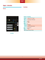
Power Button with LED (Green)
Press to power on or power off the system.
Reset Button
Press to reset the system.
HDD LED (Red)
Indicates the status of disk drives.
Status LED (Orange)
Indicates system status as below.
SATA 1 /SATA 2
Install SATA drives into the system.
Remote Power-on/Power-off Switch Connector
Connects distant power on/off switch.
USB 3.0 Ports
Connect to USB 3.0 as well as devices based on previous USB versions.
COM and DIO Ports
All COM ports can be selected among RS232, RS422 and RS485.
COM1~COM2 and COM4~COM5 can be selected between RS232 and RS232 with power via
jumper settings; COM3 and COM6 are normal RS232 ports.
The DIO port provides 8-bit digital input/output.
DVI-I (DVI-D signal) / HDMI / VGA Connector
Connects the DVI-I / HDMI / VGA connector of an LCD monitor.
Line-out and Microphone Ports
Connect audio devices such as microphones and speakers.
Gigabit LAN Ports
Connect the system to a local area network.
DC-in
DC 9~36V power input via a terminal block connector.
PCIe Expansion Slots
Provide PCIe and PCI expansion connectivity via a riser card.
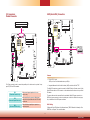
Getting to Know the EC531/EC532-SD
Chapter 1
HDD LED
HDD State
Disk access
activity
Disk drives present or not present
LED Behavior
Blink O
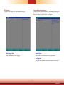
Front I/O Ports
Front View
Status LED
Suspend Mode S0 S1 S3 S4, S5
LED Behavior
Always ON
Quick Blink
(cycle 1 sec)
Slow Blink
(cycle >1 sec)
O
Rear View
HDMI
(2)
DC-in
DVI-I
(DVI-D signal)
USB 3.0
LAN 1
LAN 2
USB 3.0
SATA 2 SATA 1
VGA
COM 1
COM 2
COM 3
Remote
Power on/off
Line-out
Microphone
Expansion slots
DIO COM4 COM5 COM6
Status LED (Orange)
HDD LED (Red)
Power Button
(1)
with LED (Green)
Reset Button
Notes:
1. Please gently press the power button to avoid possible damages.
2. The HDMI is a DP/HDMI combo port but can only transmit HDMI signals (unless wired as a DP
port by request). Please plug in an HDMI cable with the right orientation and alignment to avoid
damage to the connector. You should feel resistance (due to a pin on the right) if the cable is not
inserted correctly.
Align this edge with the
left side of the connector
Angled-corner
(up)
Angled-corner
Aligning side
(left)
pin

www.d.com
9
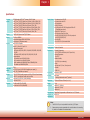
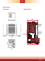
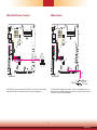
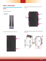
Mechanical Dimensions
Chassis Dimensions
Chapter 1
Front View
Right View
Left View
Rear View
Motherboard Dimensions
Gold finger
PCIE X4
PCIE X16
228
216.70
209.55
50
Gold finger
mini PCIe

www.d.com
10
Chapter 2 - Getting Started
Chapter 2
Preparing the System
Before you start using the system, you need the following items:
• SATA hard drive
• AC power adapter
• Optical drive (for installing software/drivers)
• Memory module
Installing Devices
The following devices can be installed in the system.
• Memory module
• SATA hard drives
• Mini PCIe and mSATA card
• PCIe and PCI expansion cards
Configuring the BIOS
To get you started, you may need to change configurations such as the date, time and the
type of hard disk drive.
1. Power-on the system.
2. After the memory test, the message “Press DEL to run setup” will appear on the screen.
Press the Delete key to enter the BIOS setup utility.
Installing an Operating System
Most operating system software can be installed using a DVD (and DVD burner) or bootable
USB drive.
Please refer to your operating system manual for instructions on installing an operating system.
Installing the Drivers
The system requires you to install drivers for some devices to operate properly. Refer to the
Supported Software chapter for instructions on installing the drivers.

www.d.com
11
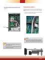
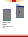
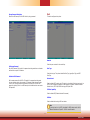
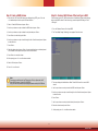
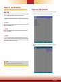
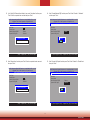
The SATA drive bay can be easily accessed witout opening the system. However, the system
does not support hot-swapping hard drives; turn off the system first.
Use the following procedure to install SATA HDD or SSD to the system:
2. Slide the HDD into the drive bay. Note that the HDD should be positioned vertically with the
SATA power connector on top of the data connector to correctly engage with the system's
SATA connectors. Then close the drive bay and lock the handle.
SATA drive bay
SATA 2 SATA 1
SATA power
Connecotr
Drive bay handle
Chapter 3 - Installing the Devices
Notes:
1. The slot is desgined to exactly fit a 2.5" SATA drive with 7mm thickness; it
cannot fit SATA drives with other sizes.
2.
Do not force to close the drive bay if the HDD is not correctly inserted.
1. Locate the drive bay on the front panel and open it by releasing the handle.

www.d.com
12
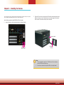
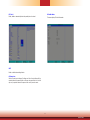
Chapter 1 Introduction
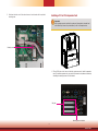
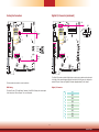
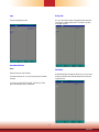
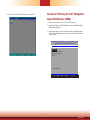
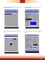
Expansion Slots Sequence
EC531-SD
Below figure shows the expansion slots of PCIe, PCI, PCI (from top to bottom)
Slot Plate
PCIe 1 (x16)
PCI 1
PCI 2
Mounting Screw and Bracket
EC532-SD
Below figure shows the expansion slots of PCIe, PCI, PCI (from top to bottom)
Slot Plate
PCIe 1 (x8)
PCI
PCIe 2 (x1)
Mounting Screw and Bracket

www.d.com
13
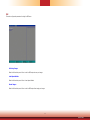
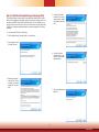
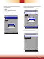
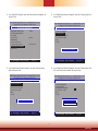
Removing the Chassis Cover
Before working inside your system, observe the following precautions:
1. Make sure the system and all other peripherals connected to it have been powered o.
2. Disconnect all power cords and cables.
3. The 4 mounting screws on the bottom of the system are used to secure the cover to the
chassis. Remove these screws and put them in a safe place for later use.
4. Lift the cover upward to open the system.
Mounting screw
Installing a SODIMM
1. Remove the supporting bracket to access the SODIMM sockets.
Mounting screw
Supporting bracket
SODIMM socket

www.d.com
14
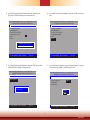
2. Grasp the module by its edges and align the memory’s notch with the socket’s
notch; then insert the memory into the socket at an angle and push it down until
you feel a click.
Notes:
1. The system supports dual-channel configuration. To enable dual-channel,
populate both SODIMM sockets.
2. The SODIMM sockets can only accept DDR4 memory modules. Please do not
install other types of memory modules.
SODIMM module
The system board is equipped with 2 Mini PCIe slots: one full-size (PCIe/USB signals) and one
half-size (USB/mSATA signals) slot. Here we will demonstrate the installation of a full-size Mini
PCIe card.
1. Grasp the Mini PCIe card by its edges and align the notch in the connector of the Mini PCIe
card with the notch in the connector on the system board.
Installing a Mini PCIe or mSATA Card
0.82mm
Important:
The bottom side of a full-size Mini PCIe module should have a component height
restriction of 0.82 mm and will sit flush against the connected half-size Mini PCIe
module if such a component is used and the half-size slot is connected with a module.

www.d.com
15
2. Push down the other end of the card and secure it on the board with the provided
mounting screw.
Mounting screw
Installing a PCI or PCIe Expansion Card
1. PCI and PCIe slots on the riser card inside the system are used to install the expansion
cards. To install the expansion cards, you need to rst remove the slot plates and bracket by
uninstalling the mounting screws on the front chassis.
Slot plate
Mounting screw and bracket
Important:
When inserting expansion cards into the system unit, please select a standard card
within 190mm (as shown in the picture below) in order to fit expansion slots.

www.d.com
16
2. Insert the expansion card into a PCI or PCIe slot on the riser card and secure the bracket
in place.
PCIe card
Rear View
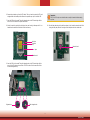
Installing a CPU
1.
Make sure the system and all other peripheral devices connected to it have been powered-o.
2. Disconnect all power cords and cables.
3. Before installing the Intel CPU,
remove the 8 mounting screws on the top of the
system unit and put them in a safe place for later use.
4. The system board is equipped with a surface mount LGA 1151 socket. This socket is ex-
clusively designed for installing a LGA 1151 packaged Intel CPU.
Important:
1. Before you proceed, make sure (1) the LGA 1151 socket comes with a protective
cap, (2) the cap is not damaged and (3) the socket’s contact pins are not bent. If
the cap is missing or the cap or contact pins are damaged, contact your dealer im-
mediately.
2. Keep the protective cap. RMA requests will be accepted and processed only if the
LGA 1151 socket comes with the protective cap.
5. Unlock the socket by pushing the load lever down, move it sideways until it is released
from the retention tab, and then lift the load lever up.

www.d.com
17
6. Remove the protective cap from the CPU socket. The cap is used to protect the CPU sock-
et against dust and harmful particles. Remove the protective cap only to install the CPU.
7. Insert the CPU into the socket. The gold triangular mark on the CPU must align with the
corner of the CPU socket as the photo shown below.
8. Unlock the socket by pushing the load lever down and moving it sideways until it is re-
leased from the retention tab and then lift the load lever up.
Retention tab
Protective
cap
Load lever
Load plate
9. Insert the CPU into the socket. The gold triangular mark on the CPU must align with the
corner of the CPU socket as shown below. The CPU’s notch will at the same time fit into
the socket’s alignment key.
Alignment key
Gold triangular mark
Important:
The CPU will fit in only one orientation and can easily be inserted without exerting
any force.
10. Close the load plate and push the load lever down to lock it under the retention tab. While
closing the load plate, slide the front edge of the load plate under the retention tab.
Retention knob

www.d.com
18
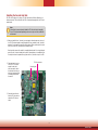
Installing the Fan and Heat Sink
The CPU must be kept cool by using a CPU fan with heat sink. Without sufficient air cir-
culation across the CPU and heat sink, the CPU will overheat damaging both the CPU and
system board.
1. Before you install the fan / heat sink, you must apply a thermal paste onto the top of
the CPU. The thermal paste is usually supplied when you purchase the fan / heat sink
assembly. Do not spread the paste all over the surface. When you later place the heat
sink on top of the CPU, the compound will disperse evenly.
Some heat sinks come with a patch of pre-applied thermal paste. Do not apply thermal
paste if the fan / heat sink already has a patch of thermal paste on its underside. Peel
the strip that covers the paste before you place the fan / heat sink on top of the CPU.
2. Place the heat sink on top
of the CPU. The 4 screw
around the heat sink,
which are used to secure
the heat sink onto the sys-
tem board, must match the
4 mounting holes around
the socket.
3. Orient the heat sink such
that the CPU fan’s cable is
nearest the CPU fan con-
nector.
Note:
A boxed Intel
®
processor already includes the CPU fan and heat sink assembly.
If your CPU was purchased separately, make sure to only use Intel
®
-certified fan
and heat sink.
Mounting hole
CPU fan connector

www.d.com
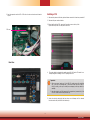
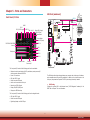
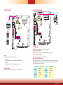
17
USB 3-4
USB 3.0
USB 1-2
USB 3.0
J22
JP2
JP3
J21
HDMI (default)/DP
DVI
System
Fan 2
1
Front
Panel
51
2
1
10
9
1
1
1
1
4
SATA Power
-
DC-in
LAN 2
LAN 1
PCIe x16 (PCIE1)
SPI Flash
BIOS
VGA
Clear CMOS
Data (JP1)
Auto Power-on
Select (JP11)
(JP9)
1
6
(JP8) (JP15)
1
6
6
1
1
2 10
COM 3
1
(JP6)
6
6
9
1
2 10
COM 2
9
1
2
(JP7) (JP14)
6
6
1
2
1
2 10
COM 1
9
1
2
16
LPC
1
2
14
4-pin power
1
1
2
3
4
PCIe x4 (PCIE2)
Power
Button
Reset
DDR4_2 SODIMM
DDR4_1 SODIMM
1
(JP5)
6
6
1
1
1
6
6
2 2
2
6
1
4
Status LED
HDD LED
2
25
26
Parallel
1
DIO Power
DIO
S/PDIF
Front Audio
2
51
1
10
9
ECX
+
SATA 3.0
USB 2.0 13-14
(JP13)
1
1
(JP12)
1
SATA 0
SATA 1
1
Mini PCIe
mSATA
System
Fan 1
1
1
bettery
1
1
1
2 12
USB 2.0
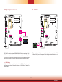
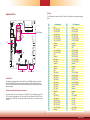
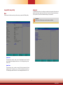
Chapter 4 - Jumper Settings
Clear CMOS Data
If you encounter the following conditions, you can reconfigure the system with the default val-
ues stored in the ROM BIOS.
a) CMOS data becomes corrupted.
b) You forgot the supervisor or user password.
To load the default values stored in the ROM BIOS, please follow these steps below:
1. Power-off the system and unplug the power cord.
2. Set the jumper pins 2 and 3 to On. Wait for a few seconds and set the jumper back to its
default setting: 1-2 On.
3. Now plug the power cord and power on the system.
2-3 On: Clear CMOS Data
1-2 On: Normal
(default)
JP1
3
1
2
3
1
2
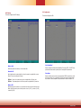
Auto Power-on Select
JP11 is used to select the method of powering on the system. If you want the system to
power-on whenever AC power comes in, set JP11 pins 2 and 3 to On. If you want to use the
power button, set pins 1 and 2 to On.
When using the JP11 “Power On” feature to power the system back on after a power failure
, the system may not power on if the power lost is resumed within 5 seconds (power flicker).
1-2 On:
Power-on via the
power button (default)
2-3 On:
Power-on via AC power
JP11
31 2
31 2

www.d.com
18
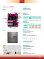
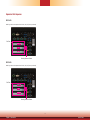
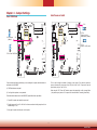
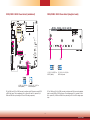
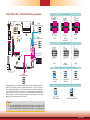
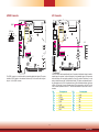
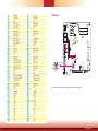
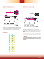
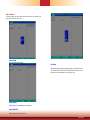
COM1/COM2 RS232 Power Select (maindboard)
JP3 (for COM1) and JP2 (for COM2) are used to configure serial COM ports to normal RS232
or RS232 with power. The pin assignments (Pin 1: optional 12V and Pin 9: optional 5V) of
COM1 and COM2 will vary according to JP3’s and JP2’s setting respectively.
USB 3-4
USB 3.0
USB 1-2
USB 3.0
J22
JP2
JP3
J21
HDMI (default)/DP
DVI
System
Fan 2
1
Front
Panel
51
2
1
10
9
1
1
1
1
4
SATA Power
-
DC-in
LAN 2
LAN 1
PCIe x16 (PCIE1)
SPI Flash
BIOS
VGA
Clear CMOS
Data (JP1)
Auto Power-on
Select (JP11)
(JP9)
1
6
(JP8) (JP15)
1
6
6
1
1
2 10
COM 3
1
(JP6)
6
6
9
1
2 10
COM 2
9
1
2
(JP7) (JP14)
6
6
1
2
1
2 10
COM 1
9
1
2
16
LPC
1
2
14
4-pin power
1
1
2
3
4
PCIe x4 (PCIE2)
Power
Button
Reset
DDR4_2 SODIMM
DDR4_1 SODIMM
1
(JP5)
6
6
1
1
1
6
6
2 2
2
6
1
4
Status LED
HDD LED
2
25
26
Parallel
1
DIO Power
DIO
S/PDIF
Front Audio
2
51
1
10
9
ECX
+
SATA 3.0
USB 2.0 13-14
(JP13)
1
1
(JP12)
1
SATA 0
SATA 1
1
Mini PCIe
mSATA
System
Fan 1
1
1
bettery
1
1
1
2 12
USB 2.0
1-3 (RI), 2-4 (DCD) On:
RS232 (default)
6
1
3-5 (+5V), 4-6 (+12V) On:
RS232 with power
6
2
1
JP2 JP3
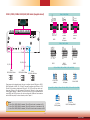
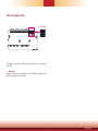
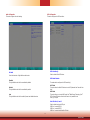
COM4/COM5 RS232 Power Select (daughter board)
JP7 JP11
1
6
(JP7)
1
6
(JP2)
1
6
(JP3)
1
6
(JP1)
1
6
(JP5)
1
6
(JP6)
1
6
(JP4)
1
6
(JP11)
1
6
(JP9)
1
6
(JP10)
1
6
(JP8)
1
6
(JP13)
1
6
(JP14)
1
6
(JP12)
DC-in
USB 3.0
USB 7-8
USB 5-6
DIO COM4 COM5
COM6
JP7 (for COM4) and JP11 (for COM5) are used to configure serial COM ports on the daughter
board to normal RS232 or RS232 with power. The pin assignments (Pin 1: optional 12V and
Pin 9: optional 5V) of COM4 and COM5 will vary according to JP7’s and JP11’s setting respec-
tively.
1-3 (RI), 2-4 (DCD) On:
RS232 (default)
3-5 (+5V), 4-6 (+12V) On:
RS232 with power
6
2
1
1
2
6
2
Page is loading ...
Page is loading ...
Page is loading ...
Page is loading ...
Page is loading ...
Page is loading ...
Page is loading ...
Page is loading ...
Page is loading ...
Page is loading ...
Page is loading ...
Page is loading ...
Page is loading ...
Page is loading ...
Page is loading ...
Page is loading ...
Page is loading ...
Page is loading ...
Page is loading ...
Page is loading ...
Page is loading ...
Page is loading ...
Page is loading ...
Page is loading ...
Page is loading ...
Page is loading ...
Page is loading ...
Page is loading ...
Page is loading ...
Page is loading ...
Page is loading ...
Page is loading ...
Page is loading ...
Page is loading ...
Page is loading ...
Page is loading ...
Page is loading ...
Page is loading ...
Page is loading ...
Page is loading ...
Page is loading ...
Page is loading ...
Page is loading ...
Page is loading ...
Page is loading ...
Page is loading ...
Page is loading ...
Page is loading ...
Page is loading ...
Page is loading ...
Page is loading ...
Page is loading ...
Page is loading ...
Page is loading ...
Page is loading ...
Page is loading ...
Page is loading ...
Page is loading ...
Page is loading ...
Page is loading ...
Page is loading ...
Page is loading ...
-
 1
1
-
 2
2
-
 3
3
-
 4
4
-
 5
5
-
 6
6
-
 7
7
-
 8
8
-
 9
9
-
 10
10
-
 11
11
-
 12
12
-
 13
13
-
 14
14
-
 15
15
-
 16
16
-
 17
17
-
 18
18
-
 19
19
-
 20
20
-
 21
21
-
 22
22
-
 23
23
-
 24
24
-
 25
25
-
 26
26
-
 27
27
-
 28
28
-
 29
29
-
 30
30
-
 31
31
-
 32
32
-
 33
33
-
 34
34
-
 35
35
-
 36
36
-
 37
37
-
 38
38
-
 39
39
-
 40
40
-
 41
41
-
 42
42
-
 43
43
-
 44
44
-
 45
45
-
 46
46
-
 47
47
-
 48
48
-
 49
49
-
 50
50
-
 51
51
-
 52
52
-
 53
53
-
 54
54
-
 55
55
-
 56
56
-
 57
57
-
 58
58
-
 59
59
-
 60
60
-
 61
61
-
 62
62
-
 63
63
-
 64
64
-
 65
65
-
 66
66
-
 67
67
-
 68
68
-
 69
69
-
 70
70
-
 71
71
-
 72
72
-
 73
73
-
 74
74
-
 75
75
-
 76
76
-
 77
77
-
 78
78
-
 79
79
-
 80
80
-
 81
81
-
 82
82


DFI EC531-SD/EC532-SD Owner's manual
- Category
- Motherboards
- Type
- Owner's manual
- This manual is also suitable for
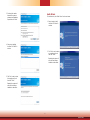
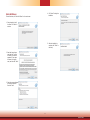
Ask a question and I''ll find the answer in the document
Finding information in a document is now easier with AI
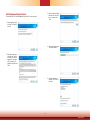
Related papers
-
DFI AL053 Reference guide
-
-
-
-
-
-
-
-
-
Other documents
-
Geovision GV-COMV2 Datasheet
-
TESmart HKS1601A1U User manual
-
Sweex ST152 Datasheet
-
EXSYS EX-48030 Specification
-
Avalue Technology LPC-15WD510 Quick Reference Manual
-
-
-
BCM QS440BXP User manual
-
 ANTAIRA MSC-102B1 Installation guide
-
MATSONIC MS7177CT User manual
