Page is loading ...

XStream-PKG-E™ Ethernet RF Modem
Product Manual v5.x00
For XStream RF Modem Part Numbers
X09-001PK…-E…
X09-009PK…-E…
X09-019PK…-E…
X24-009PK…-E...
X24-019PK…-E…
XH9-001PK…-E...
XH9-009PK…-E…
XH9-019PK…-E…
900 MHz and 2.4 GHz Stand-alone RF Modems by Digi International Inc.

XStream‐PKG‐E™ Ethernet RF Modem – Product Manual v5.x00
© 2014 Digi International Inc.
ii
XStream-PKG-E Ethernet Modem – Product Manual v5.x00
(Part number 90002207 B)
Revision
Date
Description
B
10/15/14
Minor changes and new part number
© 2014 Digi International Inc. All rights reserved
Digi, Digi International Inc., the Digi logo, and XStream
®
are
trademarks or registered trademarks in the United States and
other countries worldwide. All other trademarks mentioned
in this document are the property of their respective owners.
Information in this document is subject to change without
notice and does not represent a commitment on the part of
Digi International Inc. Digi provides this document “as is,”
without warranty of any kind, expressed or implied,
including, but not limited to, the implied warranties of fitness
or merchantability for a particular purpose. Digi may make
improvements and/or changes in this manual or in the
product(s) and/or the program(s) described in this manual at
any time.

XStream‐PKG‐E™ Ethernet RF Modem – Product Manual v5.x00
© 2014 Digi International Inc.
iii
Contents
1. XStream Ethernet RF Modem 4
1.1. Features Overview 4
1.1.1. Worldwide Acceptance 4
1.2. Product Overview 5
1.2.1. Specifications 5
1.3. External Interface 6
1.3.1. Front and Back Views 6
2. System Setup 7
2.1. Data Radio System Components 7
2.1.1. System Description 7
2.2. Com Port Communications 8
2.2.1. Install Software 8
2.2.2. Run Range Test 8
3. RF Modem Operation 9
3.1. Modes of Operation 9
3.1.1. Idle Mode 9
3.1.2. Transmit Mode 9
3.1.3. Receive Mode 11
3.1.4. Sleep Mode 11
3.1.5. Command Mode 14
4. RF Modem Configuration 16
4.1. Hands-On Programming Examples 16
4.1.1. Configuration Setup Options 16
4.1.2. AT Command Examples 17
4.1.3. Binary Command Example 21
4.2. Command Reference Table 18
4.3. Command Descriptions 19
5. RF Communication Modes 38
5.1. Addressing 39
Appendix A: Agency Certifications 50
FCC Certification 50
FCC Notices 50
OEM Labeling Requirements 51
Antenna Usage 51
FCC Approved Antennas 52
IC (Industry Canada) Certification 54
Appendix B: Additional Information 54
1-Year Warranty 54
Ordering Information 54
Contact Digi 55
5.1.1. Address Recognition 39
5.2. Basic Communications 40
5.2.1. Streaming Mode (Default)
5.2.2. Repeater Mode 41
40
5.3. Acknowledged Communications 44
5.3.1. Acknowledged Mode 44
5.3.2. Multi-Streaming Mode 46

XStream‐PKG‐E™ Ethernet RF Modem – Product Manual v5.x00
© 2014 Digi International Inc.
4
1. XStream Ethernet RF Modem
XStream-PKG-E Ethernet RF Modems extend system performance and
flexibility by adding serial connectivity to Ethernet networks.
Digi RF Modems handle the complexities inherent to RF
communications (modulation, demodulation, frequency synthesizers,
amplifiers, filters, FCC approvals, etc.), so OEMs and integrators can
focus resources beyond the wireless portion of the data system.
1.1. Features Overview
Long
Range
at
a
Low
Cost
9XStream-PKG-E (900 MHz) Range:
•
Indoor/Urban: up to 1500’ (450 m)
•
Outdoor line-of-sight: up to 7 miles (11 km)
w/2.1 dBm dipole antenna
•
Outdoor line-of-sight: up to 20 miles (32 km)
w/high gain antenna
24XStream-PKG-E (2.4 GHz) Range:
•
Indoor/Urban: up to 600’ (180 m)
•
Outdoor line-of-sight: up to 3 miles (5 km)
w/2.1 dBm dipole antenna
•
Outdoor line-of-sight: up to 10 miles (16 km)
w/high gain antenna
Receiver sensitivity: -110 dBm (@ 900 MHz),
–105 dBm (@ 2.4
GHz)
Advanced Networking and
Secur
i
ty
True Peer-to-Peer (no “master” required), Point-to-
Point, Point-to-Multipoint and Multidrop
Retries and Acknowledgements
FHSS (Frequency Hopping Spread Spectrum)
7 hopping channels, each with over 65,000 unique
network addresses available
Easy-to-Use
Out-of-Box RF Experience -
no configuration required
No Master/Slave setup dependencies
Advanced configurations using
Windows software and AT Commands
7-28 VDC power supply
Transparent Operation
Support for multiple data formats
(parity and data bits)
Portable (small form factor and
low power)
Software-selectable interfacing rates
Support for multiple data formats
XII™ Interference Immunity
Power-saving Sleep Modes
(as low as 230 mA)
1.1.1. Worldwide Acceptance
FCC Certified (USA) Refer to Appendix A for FCC Requirements.
Systems
that
contain
XStream
RF
Modems
automatically
inherit
Digi
Certifications.
ISM (Industrial, Scientific and Medical) frequency band
Manufactured
under
ISO
9001:2000
registered
standards
9XStream-PKG-E (900 MHz) RF Modems approved for use in US, Canada, Australia,
(and more).

XStream‐PKG‐E™ Ethernet RF Modem – Product Manual v5.x00
© 2014 Digi International Inc.
5
1.2. Product Overview
The XStream-PKG-E RF Modem comes configured to provide immediate wireless links between
devices; however, the RF modem can be configured for additional functionality through the use of
a simple AT command interface (Refer to the Command Mode (p18) and RF Modem Configuration
(p20) sections for programming options).
1.2.1. Specifications
Table 1‐01. XStream‐PKG‐E Ethernet RF Modem Specifications
Specification 9XStream-PKG-E (900 MHz) 24XStream-PKG-E (2.4 GHz)
Performance
Indoor/Urban Range
Up to 1500’ (450 m)
Up to 600’ (180 m)
Outdoor LOS Range
Up to 7 miles (11 km) w/ 2.1 dBm dipole antenna
Up to 20 miles (32 km) w/ high-gain antenna
Up to 3 miles (5 km) w/ 2.1 dBm dipole antenna
Up to 10 miles (16 km) w/ high-gain antenna
Transmit Power Output
100 mW (20 dBm)
50 mW (17 dBm)
Interface Data Rate
Software selectable 125 – 65,000 bps
(Including non-standard baud rates)
Software selectable 125 – 65,000 bps
(Including non-standard baud rates)
Throughput Data Rate
9,600 bps
19,200 bps
9,600 bps
19,200 bps
RF Data Rate
10,000 bps
20,000 bps
10,000 bps
20,000 bps
Receiver Sensitivity
-110 dBm
-107 dBm
-105 dBm
-102 dBm
Power Requirements
Supply Voltage
7-28 VDC
7-28 VDC
Receive (RX) Current*
240 mA (@ 9V)
260 mA (@ 9V)
Transmit (TX) Current*
320 mA (@ 9V)
340 mA (@ 9V)
Power Down Current*
230 mA (@ 9V)
230 mA (@ 9V)
General
Frequency
902-928 MHz
2.4000-2.4835 GHz
Spread Spectrum
Frequency Hopping, Wide band FM modulator
Network Topology
Peer-to-Peer, Point-to-Point, Point-to-Multipoint, Multidrop
Supported Network Protocols
ARP, UDP, TCP, ICMP, Telnet, TFTP, AutoIP, DHCP, HTTP and SNMP (read-only)
Channel Capacity
7 hop sequences share 25 frequencies
Data Connection
RJ-45 Female Ethernet Connection
Physical Properties
Enclosure
Extruded aluminum, black, anodized
Enclosure Size
2.750” x 5.500” x 1.125” (6.99cm x 13.97cm x 2.86cm)
Weight
7.1 oz. (200g)
Operating Temperature
0 to 70º C (commercial), -40 to 85º C (industrial)
Antenna
Type
½ wave dipole whip, 6.75” (17.1 cm), 2.1 dBi Gain
Connector
Reverse-polarity SMA (RPSMA)
Impedance
50 ohms unbalanced
Certifications
FCC Part 15.247
OUR9XSTREAM
OUR-24XSTREAM
Industry Canada (IC)
4214A-9XSTREAM
4214A 12008
* Divide by 2 for 18V supply (constant wattage from 7 to 28V)

XStream‐PKG‐E™ Ethernet RF Modem – Product Manual v5.x00
© 2014 Digi International Inc.
6
3 LEDs ON = Very Strong Signal (> 30 dB fade margin)
2 LEDs ON = Strong Signal (> 20 dB fade margin)
1 LED ON
=
Moderate Signal (> 10 dB fade margin)
0 LED ON = Weak Signal (< 10 dB fade margin)
1.3. External Interface
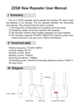
1.3.1. Front and Back Views
Figure 1‐01. Front View
1-01a. Power Switch
Move Power Switch to the ON (up) position to power the
XStream PKG-E Ethernet RF Modem.
1‐01d. RJ‐45 Port
1‐01c. RSSI LEDs (all green)
1‐01e. Power
Connector*
1-01b. I/O and Power LEDs
LEDs indicate modem activity as follows:
Yellow (top LED) = Serial Data Out (to host)
Green (middle) = Serial Data In (from host)
Red (bottom) = Power/TX Indicator (Red light is on
when powered and pulses off briefly during RF transmission)
1‐01b. I/O and Power LEDs
1‐01a. Power Switch
* The Ethernet RF Modem does not support
Power-over-Ethernet (PoE). The device
cannot be powered directly from a PoE port
on a compatible hub.
However, it may be useful to send power on
the unused wires of the CAT-5 cable in
situation where the radio will be mounted
in
a
location that optimizes radio coverage but
may not have a power outlet nearby. There
are several third part devices available that
can inject the power onto the cable and then
remove it at the remote side.
Figure 1‐02. Back View
1-01c. RSSI LEDs
RSSI LEDs indicate the amount of fade margin present in an active
wireless link. Fade margin is the difference between the incoming
signal strength and the modem’s receiver sensitivity.
1-01d. RJ-45 Ethernet Port
Standard Female RJ-45 connector is used to connect unshielded
twisted-pair CAT5 cabling.
1-01e. Power Connector *
7-28 VDC Power Connector.
1-02a. Reset Switch
Reset Switch forces the RF Modem to reset (or re-boot).
1-02b. Antenna Port
Antenna Port is a 50 Ω RF signal connector for connecting to an
external antenna. Connector type is Reverse Polarity (RPSMA)
female. The RPSMA has threads on the outside of a barrel and a
male center conductor.
1‐02a. Reset Switch
1‐02c. Config
Switch
1‐02b. Antenna Port
1-02c. Config (Configuration) Switch
The Config Switch provides an alternate way to enter AT Command
Mode.
To enter Command Mode at the Modem’s default baud rate:
Simultaneously press the Reset (1-02a) and Config switches;
release the Reset Switch; then after 1 sec., release the Config
Switch. The RF Modem then enters AT Command Mode at the
modem’s default baud rate.

XStream‐PKG‐E™ Ethernet RF Modem – Product Manual v5.x00
© 2014 Digi International Inc.
7
2. System Setup
2.1. Data Radio System Components
XStream Radio Modems are designed to provide long range wireless links between devices of a
data system. The PKG-E Ethernet RF Modem connects serial modems to Ethernet networks.
The following devices will be used to describe a data system that includes the XStream-PKG-E
Ethernet RF Modem:
XStream-PKG-E Ethernet RF Modem (“PKG-E”): The Ethernet RF Modem is
an Ethernet-connected serial modem used for communication with other Digi
serial modems. The Ethernet RF Modem is not a wireless Ethernet Bridge
intended for Ethernet connectivity on both the remote and base sides of a
wireless link.
XStream-PKG-R RS-232/485 RF Modem (“PKG-R”): The RS-232/485 RF
Modem is a serial modem that can be identified by its DB-9 serial port and 6-
switch DIP Switch.
XStream OEM RF Module (“OEM RF Module”): The OEM RF Module
is
mounted inside all XStream-PKG RF Modems and may be integrated into OEM-
designed products to transmit and receive data over-the-air.
2.1.1. System Description
The PKG-E Ethernet RF Modem can be used as an access point in a network of Digi RS-
232/RS-485 RF Modems (or other OEM RF Module Embedded Devices). XStream RF Modems
support point-to-point, peer-to-peer, point-to-multipoint and multidrop network topologies. Below
is an example of a typical point-to-multipoint application:
Figure 2‐01. XStream‐PKG‐E Ethernet RF Modem in a Point‐to‐Multipoint Data Radio System

XStream‐PKG‐E™ Ethernet RF Modem – Product Manual v5.x00
© 2014 Digi International Inc.
8
2.2. Com Port Communications
2.2.1. Install Software
The XCTU and Com Port Redirector software facilitate communications through a PC’s com port.
Follow the instructions below to setup a com port for configuring and testing RF modems.
Installation #1: To Install the XCTU Software
Go to the XCTU Software page at www.digi.com/xtcu and click “Download”. Launch the appropriate
XCTU installer and follow the prompts on the installation screens.
Installation #2: To Install the Ethernet Com Port Redirector
Go to the Knowledge Base page at www.digi.com/support/kbase. In the Keyword box, type “2033”
and press “Search”. Click the link to the Knowledge Base article for detailed instructions on how to
install the Device Installer and Com Port Redirector.
2.2.2. Run Range Test (XCTU)
When testing a wireless link, Digi suggests creating the link using the following
components:
•
XStream-PKG-E Ethernet RF Modem (connected to a local network)
•
XStream-PKG-R RS-232/485 RF Modem (w/ loopback adapter)
•
PC (connected to a local network)
•
Accessories (Loopback adapter, CAT5 UTP cable, power supplies and RPSMA antennas)
Hardware Setup:
1. Connect the XStream-PKG-E (Ethernet) RF Modem and a PC to active Ethernet ports of the
same local network using CAT5 cables (included w/ PKG-EA accessories package).
2. Attach the serial loopback adapter to the DB-9 serial connector of the XStream-PKG-R (RS-
232) RF Modem. The serial loopback adapter configures the PKG-R RF Modem to function as
a repeater by looping serial data back into the modem for retransmission.
3. Configure the PKG-R (RS-232) RF Modem for RS-232 operation using
the built-in DIP Switch. Dip Switch 1 should be ON (up) and the
remaining switches should be OFF (down).
4. Attach RPSMA antennas to both RF Modems.
5. Power both RF Modems with power supplies (included w/ accessories package).
Figure 2‐02. Hardware Setup for Range Test
Run Range Test:
Launch XCTU and click on “Help Contents” located under the question mark button. Refer to Section
5.5 - Range Test Tool of the XCTU User's Guide for detailed instructions on how to conduct a range
test using XCTU.

XStream‐PKG‐E™ Ethernet RF Modem – Product Manual v5.x00
© 2014 Digi International Inc.
9
3. RF Modem Operation
3.1. Modes of Operation
An on-board RF module enables the XStream RF Modem to send and receive data over-the-air.
The RF modem operates in five modes.
Figure 3‐01. RF Modem Modes of Operation
The RF modem can only be in one mode at a time.
3.1.1. Idle Mode
When not receiving or transmitting data, the RF modem is in Idle Mode. The RF modem uses the
same amount of power in Idle Mode as it does in Receive Mode.
The modem shifts into the other modes of operation under the following conditions:
•
Serial data is received in the DI Buffer (Transmit Mode)
•
Valid RF data is received through the antenna (Receive Mode)
•
Command Mode Sequence is issued (Command Mode)
•
Sleep Mode condition is met (Sleep Mode)
After responding to any of the preceding conditions, the modem automatically transitions back
into Idle Mode.
3.1.2. Transmit Mode
Note: RF reception must
complete before the
modem is able to enter
into Transmit Mode.
When the first byte of serial data is received from the UART in the DI buffer, the modem
attempts to shift to Transmit Mode and initiate an RF connection with other modems. After
transmission is complete, the modem returns to Idle Mode.
RF transmission begins after either of the following criteria is met:
1. RB bytes have been received in the DI buffer and are pending for RF transmission (refer to
RB (Packetization Threshold) command, p32).
The RB parameter may be set to any value between 1 and the RF packet size (PK), inclusive.
When RB = 0, the packetization threshold is ignored.
2. At least one character has been received in the DI buffer (pending for RF transmission) and
RO time has been observed on the UART (refer to RO (Packetization Timeout) command).
The timeout can be disabled by setting RO to zero. In this case, transmission will begin after
RB bytes have been received in the DI buffer.

XStream‐PKG‐E™ Ethernet RF Modem – Product Manual v5.x00
© 2014 Digi International Inc.
10
Figure 3‐02. Data Transmission Sequence
After either RB or RO conditions are met,
the modem then initializes a
communications channel. (Channel
initialization is the process of sending an
RF initializer that synchronizes receiving
modems with the transmitting modem.
During channel initialization, incoming
serial data accumulates in the DI buffer.)
Serial data in the DI buffer is grouped
into RF packets (refer to PK (RF Packet
Size)); converted to RF data; then
transmitted over-the-air until the DI
buffer is empty.
RF data, which includes the payload data, follows the RF initializer. The payload includes up to
the maximum packet size (PK Command) bytes. As the transmitting modem nears the end of the
transmission, it inspects the DI buffer to see if more data exists to be transmitted. This could be
the case if more than PK bytes were originally pending in the DI buffer or if more bytes arrived
from the UART after the transmission began. If more data is pending, the transmitting modem
assembles a subsequent packet for transmission.
RF Data
Packet
The RF packet is the sequence of data used for communicating information between Digi
Modems. An RF Packet consists of an RF Initializer and RF Data.
Figure 3‐03. RF Data Packet Components
* When streaming multiple RF packets,
the RF Initializer is only sent in front of the
first packet.
RF Initializer
An RF initializer is sent each time a new connection sequence begins. The RF initializer contains
channel information that notifies receiving modems of information such as the hopping pattern
used by the transmitting modem. The first transmission always sends an RF initializer.
An RF initializer can be of various lengths depending on the amount of time determined to be
required to prepare a receiving modem. For example, a wake-up initializer is a type of RF
initializer used to wake remote modems from Sleep Mode (Refer to the FH, LH, HT and SM
Commands for more information). The length of the wake-up initializer should be longer than the
length of time remote modems are in cyclic sleep.
Header
The header contains network addressing information that filters incoming RF data. The receiving
modem checks for a matching Hopping Channel (HP parameter), Vendor Identification Number
(ID parameter) and Destination Address (DT parameter). Data that does not pass through all
three network filter layers is discarded.
CRC (Cyclic Redundancy Check)
To verify data integrity and provide built-in error checking, a 16-bit CRC (Cyclic Redundancy
Check) is computed for the transmitted data and attached to the end of each RF packet. On the
receiving end, the receiving modem computes the CRC on all incoming RF data. Received data
that has an invalid CRC is discarded (Refer to the Receive Mode section, next page).

XStream‐PKG‐E™ Ethernet RF Modem – Product Manual v5.x00
© 2014 Digi International Inc.
11
3.1.3. Receive Mode
If a modem detects RF data while operating in Idle Mode, the modem transitions into Receive
Mode to start receiving RF packets.
Figure 3‐04. Reception of RF Data
After a packet is received, the modem checks the
CRC (cyclic redundancy check) to ensure that the
data was transmitted without error. If the
CRC
data
bits on the incoming packet are invalid, the
packet is discarded. If the CRC is valid, the packet
proceeds to the DO Buffer.
The modem returns to Idle Mode after valid RF
data is no longer detected or after an error is
detected in the received RF data. If serial data is
stored in the DI buffer while the modem is in
Receive Mode, the serial data will be transmitted
after the modem is finished receiving data and
returns to Idle Mode.
3.1.4. Sleep Mode
Sleep Modes enable the XStream Modem to operate at minimal power consumption when not in
use. Three Sleep Mode options are available:
•
Pin Sleep (Host Controlled)
•
Serial Port Sleep (Wake on Serial Port activity)
•
Cyclic Sleep (Wake on RF activity)
For the modem to transition into Sleep Mode, the modem must have a non-zero SM (Sleep Mode)
Parameter and one of the following must occur:
1. The modem is idle (no data transmission or reception) for a user-defined period of time
(Refer to ST (Time before Sleep)
Command).
2.
SLEEP pin is asserted (only for Pin Sleep option).
In Sleep Mode, the modem will not transmit or receive data until the modem first transitions to
Idle Mode. All Sleep Modes are enabled and disabled using SM Command. Transitions into and
out of Sleep Modes are triggered by various mechanisms as shown in the table below.
Table 3‐01. Summary of Sleep Mode Configurations
Sleep Mode
Setting
Transition into
Sleep Mode
Transition out of
Sleep Mode
Related
Commands
Pin Sleep
(SM = 1)
A microcontroller can shut down and wake modems by
asserting (high) SLEEP pin.
Note: The module will complete a transmission or
reception before activating Pin Sleep.
De-assert SLEEP pin.
SM
Serial Port Sleep
(SM = 2)
Automatic transition to Sleep Mode occurs after a user-
defined period of inactivity (no transmitting or receiving
of data). The period of activity is defined using the ST
(Time before Sleep) Command.
When serial byte is
received on the DI pin.
SM, ST
Cyclic Sleep
(SM = 3-8)
Automatic transition to Sleep Mode occurs in cycles as
defined by the SM (Sleep Mode) Command.
Note: The cyclic sleep time interval must be shorter than
the “Wake-up Initializer Timer” (set by LH Command).
After the cyclic sleep time
interval elapses.
Note: Modem can be
forced into Idle Mode if PW
(Pin Wake-up) Command
is issued.
SM, ST, HT, LH,
PW
For more information about Sleep Modes, refer to the individual commands listed in “Related
Commands” column of the table.

XStream‐PKG‐E™ Ethernet RF Modem – Product Manual v5.x00
© 2014 Digi International Inc.
12
Pin Sleep (SM = 1)
Pin Sleep requires the least amount of power. In order to achieve this state, DI3 (SLEEP) pin
must be asserted (high). The modem remains in Pin Sleep until the DI3 pin is de-asserted.
After enabling Pin Sleep, the SLEEP pin controls whether the XStream Modem is active or in Sleep
Mode. When DI3 is de-asserted (low), the modem is fully operational. When DI3 is
asserted
(high),
the modem transitions to Sleep Mode and remains in its lowest power-consuming state
until the DI3 (SLEEP) pin is de-asserted. DI3 is only active if the modem is setup to operate in
this mode; otherwise the pin is ignored.
Once in Pin Sleep Mode, DO2 ( ) is de-asserted (high), indicating that data should not be sent
to the modem. The PWR pin is also de-asserted (low) when the modem is in Pin Sleep Mode.
Note: The module will complete a transmission or reception before activating Pin Sleep.
Serial Port Sleep (SM = 2)
Serial Port Sleep is a Sleep Mode in which the XStream Modem runs in a low power state until
serial data is detected on the DI pin.
When Serial Port Sleep is enabled, the modem goes into Sleep Mode after a user-defined period
of inactivity (no transmitting or receiving of data). This period of time is determined by ST (Time
before Sleep) Command. Once a character is received through the DI pin, the modem returns to
Idle Mode and is fully operational.
Cyclic Sleep (SM = 3-8)
Cyclic Sleep is the Sleep Mode in which the XStream Modem enters into a low-power state and
awakens periodically to determine if any transmissions are being sent.
When Cyclic Sleep settings are enabled, the XStream Modem goes into Sleep Mode after a user-
defined period of inactivity (no transmission or reception on the RF channel). The user-defined
period is determined by ST (Time before Sleep) Command.
While the modem is in Cyclic Sleep Mode, DO2 ( ) is de-asserted (high) to indicate that data
should not be sent to the modem during this time. When the modem awakens to listen for data,
DO2 is asserted and any data received on the DI Pin is transmitted. The PWR pin is also de-
asserted (low) when the modem is in Cyclic Sleep Mode.
The modem remains in Sleep Mode for a user-defined period of time ranging from 0.5 seconds to
16 seconds (SM Parameters 3 through 8). After this interval of time, the modem returns to Idle
Mode and listens for a valid data packet for 100 ms. If the modem does not detect valid data (on
any frequency), the modem returns to Sleep Mode. If valid data is detected, the modem
transitions into Receive Mode and receives incoming RF packets. The modem then returns
to
Sleep Mode after a Period of inactivity that is determined by ST “Time before Sleep” Command.
The modem can also be configured to wake from cyclic sleep when SLEEP/DI3 is de-asserted
(low). To configure a modem to operate in this manner, PW (Pin Wake-up) Command must be
issued. Once DI3 is de-asserted, the modem is forced into Idle Mode and can begin transmitting
or receiving data. It remains active until no data is detected for the period of time specified by
the ST Command, at which point it resumes its low-power cyclic state.
Note: The cyclic interval time defined by SM (Sleep Mode) Command must be shorter than the interval
time defined by LH (Wake-up Initializer Timer). (Refer to figures below.)

XStream‐PKG‐E™ Ethernet RF Modem – Product Manual v5.x00
© 2014 Digi International Inc.
13
Cyclic Scanning. Each RF transmission consists of an RF Initializer and payload. The wake-up
initializer contains initialization information and all receiving modems must wake during the
wake-up initializer portion of data transmission in order to be synchronized with the transmitting
modem and receive the data.
Figure 3‐05. Correct Configuration (LH > SM)
Length of the wake‐up initializer exceeds the time interval of Cyclic Sleep. The receiver is guaranteed to detect
the wake‐up initializer and receive the accompanying payload data.
Figure 3‐06. Incorrect Configuration (LH < SM)
Length of wake‐up initializer is shorter than the time interval of Cyclic Sleep. This configuration is vulnerable
to the receiver waking and missing the wake‐up initializer (and therefore also the accompanying payload data).

XStream‐PKG‐E™ Ethernet RF Modem – Product Manual v5.x00
© 2014 Digi International Inc.
14
3.1.5. Command Mode
To modify or read RF module parameters, the module must first enter into Command Mode - a
state in which incoming characters are interpreted as commands and parameters. Two command
types are available for programming the RF modem: AT Commands and Binary Commands.
IMPORTANT: For modified parameter values to persist in the RF modem’s registry, changes must be
saved to non-volatile memory using the WR (Write) Command. Otherwise, parameter values are
restored to previously saved values the next time the RF modem is powered off and then on again.
AT Commands
Enter AT Command Mode:
1. Send the 3-character command sequence “+++” and observe guard times before and after
the command characters. (Refer to “Default AT Command Mode Sequence” below.) The
“Terminal” tab (or other serial communications software) of the XCTU Software can be used
to enter the sequence.
(OR)
2. Assert (low) the CONFIG pin and turn the power going to the RF modem off and back on. To
achieve this result, simultaneously press the Reset (Figure 1-02a) and Config (Figure 1-02c)
switches; release the Reset Switch; then after 1 sec., release the Config Switch. The RF
Modem then enters AT Command Mode at the modem’s default baud rate.
The AT Command Mode Sequence (default parameter values are shown in parenthesis):
•
Observe Guard Time Before (ATBT = 0x0A, no characters sent for one second)
•
Enter three copies of the Command Sequence Character (ATCC = 0x2B, ASCII “+++“)
•
Observe Guard Time After (ATAT = 0x0A, no characters sent for one second)
To Send AT Commands:
Send AT commands and parameters using the syntax shown below:
Figure 3‐07. Syntax for sending AT Commands
NOTE: To read a parameter value stored in a register, leave the parameter field blank.
The preceding example would change the RF modem’s destination address to “1F”. To store the
new value to non-volatile (long term) memory, the Write (ATWR) Command must follow.
System Response. When a command is sent to the modem, the modem will parse and execute
the command. Upon successful execution of a command, the modem returns an “OK” message. If
execution of a command results in an error, the modem returns an “ERROR” message.
To Exit AT Command Mode:
1. Send ATCN (Exit Command Mode) Command.
(OR)
2. If no valid AT Commands are received within the time specified by CT (Command Mode
Timeout) Command, the Modem automatically returns to Idle Mode.
For examples that step through the programming the modem using AT Commands, refer to the
RF Modem Configuration (p20) chapter.

XStream‐PKG‐E™ Ethernet RF Modem – Product Manual v5.x00
© 2014 Digi International Inc.
15
Binary Commands
Sending and receiving parameter values using binary commands is the fastest way to change
operating parameters of the XStream RF Modem. Binary commands are used most often to
sample signal strength (RS parameter) and/or error counts; or change modem addresses and
channels for polling data systems. Since the sending and receiving of register values takes place
through the same serial data path as “live” data (received RF payload), interference between the
two types of data can be a concern.
Common questions about using binary commands:
•
What are the implications of asserting CMD while live data is being sent or received?
•
After sending serial data, is there a minimum time delay before CMD can be asserted?
•
Is a delay required after CMD is de-asserted before payload data can be sent?
•
How does one discern between live data and data received in response to a command?
The CMD pin must be asserted in order to send binary commands to the RF modem. The CMD pin
can be asserted to recognize binary commands anytime during the transmission or reception of
data. The status of the CMD signal is only checked at the end of the stop bit as the byte is shifted
into the serial port. The application does not allow control over when data is received, except by
waiting for dead time between bursts of communication.
If the command is sent in the middle of a stream of payload data to be transmitted, the command
will essentially be executed in the order it is received. If the radio is continuously receiving data,
the radio will wait for a break in the received data before executing the command. The signal
will frame the response coming from the binary command request (Figure 3-08).
A minimum time delay of 100 µs (after the stop bit of the command byte has been sent) must be
observed before the CMD pin can be de-asserted. The command executes after all parameters
associated with the command have been sent. If all parameters are not received within 0.5
seconds, the modem returns to Idle Mode.
Note: When parameters are sent, they are two bytes long with the least significant byte sent first.
Binary commands that return one parameter byte must be written with two parameter bytes.
Refer to p21 for a binary programming example.
Commands can be queried for their current value by sending the command logically ORed (bit-
wise) with the value 0x80 (hexadecimal) with CMD asserted. When the binary value is sent (with
no parameters), the current value of the command parameter is sent back through the DO pin.
Figure 3‐08. Binary Command Write then Read
Signal #4 is CMD
Signal #1 is the DIN signal to the radio
Signal #2 is the DOUT signal from the radio
Signal
#3
is
In this graph, a value was written to a register and then
read out to verify it. While not in the middle of other
received data, note that the (DO2 pin) signal
outlines the data response out of the modem.
IMPORTANT: For the XStream Modem to
recognize a binary command, the RT (DI2 Configuration) parameter must be set to
one. If binary programming is not enabled (RT ≠ 1), the modem will not recognize
that the CMD pin is asserted and therefore will not recognize the data as binary
commands.

XStream‐PKG‐E™ Ethernet RF Modem – Product Manual v5.x00
© 2014 Digi International Inc.
16
4. RF Modem Configuration
4.1. Hands-On Programming Examples
For more information about entering Command Mode, sending
commands and exiting Command Mode, refer to the Command Mode
section (p18).
4.1.1. Configuration Setup Options
After installing the XCTU and Com Port Redirector Software (refer to
p8) to a PC, use one of the connection options below to send
commands to the XStream-PKG-E Ethernet RF Modem.
Examples in this
section
cite
the use of
Digi
’
s
X‐CTU
Software
for
programming
the
RF
modem. Other
programs
such as Telnet
Software
can also be used
to
program the
modem.
Option #1 – Local Network
Connection
Connect a PC and the Ethernet RF Modem to active Ethernet connections of the same local
network (as shown in the figure below).
Figure 4‐01. Local Network Connection
Option #2 – Direct PC Connection
Connect the Ethernet RF Modem directly to the PC through the PC’s Ethernet port (as shown in
the figure below).
Figure
4‐02.
Direct
PC
Connection
Configuration Setup:
1. Install both the XCTU Software and the Ethernet Com Port Redirector (Refer to the “Install
Software” (p8) section for more information).
2. Connect the Ethernet RF Modem to a PC using either a Local Network (p20) or a Direct PC (20)
connection.
3. Follow the steps outlined in the “Ethernet RF Modem Discovery” section (p9) to identify the com
port that will be used to configure the RF modem.
4. Launch the XCTU Software on the PC and select the PC Settings tab.
5. Make sure values shown in the fields of the “Com Port Setup” section match those of the
Ethernet RF Modem.
(This example is continued on the following page)

XStream‐PKG‐E™ Ethernet RF Modem – Product Manual v5.x00
© 2014 Digi International Inc.
17
After following the steps outlined in the Configuration Setup section (previous page), the RF
modem is ready to be programmed. The following steps utilize the Terminal tab of the X-CTU
Software to read and write parameter values.
Highlight the Com Port from the ‘Select Com Port’ list that is mapped to the Ethernet RF
Modem.
Select the Terminal tab; then enter the following characters:
Sent AT Command System Response
OK <CR> (Enter RF modem into AT Command Mode)
ATDT <Enter> 0 <CR> (Read Current destination address)
ATDT1A0D <Enter> OK <CR> (Change destination address to 0x1A0D)
ATWR <Enter> OK <CR> (Write new value to non-volatile memory)
ATCN <Enter> OK <CR> (Exit AT Command Mode)
NOTE: Multiple commands can be sent on one command line. The following command line entries
will yield the same results as above. Commands must be separated by a comma (“,”).
Sent AT Command System Response
OK <CR> (Enter RF modem into AT Command Mode)
ATDT <Enter> 0 <CR> (Read Current destination address)
ATDT1A0D, WR, CN <Enter> OK <CR> (Execute multiple commands)
Both of the preceding examples change the RF modem destination address. If the RF modem is
to communicate with other RF modems, their destination addresses must match.
4.1.2. AT Command Examples
Send AT Commands (Using the XCTU Terminal Tab):
Send AT Commands (Using the XCTU Modem Configuration Tab):
4.1.3. Binary Command Example
Send Binary Commands:
Example: Use binary commands to change the XStream Modem’s destination address to 0x1A0D and
save the new address to non-volatile memory.
1. RT Command must be set to “1” in AT Command Mode to enable binary programming.
2. Assert CMD (Pin is driven high.) (Enter Binary Command Mode)
3. Send Bytes (Parameter bytes must be 2 bytes long):
00 (Send DT (Destination Address) Command)
0D (Least significant byte of parameter bytes)
1A (Most significant byte of parameter bytes)
08 (Send WR (Write) Command)
4. De-assert CMD (Pin is driven low).
After following the steps outlined in the Configuration Setup section (previous page), the RF
modem is ready to be programmed. The following steps utilize the Modem Configuration tab of
the X-CTU Software to read currently stored parameter values; then restore the modem
parameters to their factory-default states.
Highlight the Com Port from the ‘Select Com Port’ list that is mapped to the Ethernet RF
Modem.
Select the Modem Configuration tab.
Select the ‘Read’ button. (Currently stored parameter values are displayed.)
Select the ‘Restore’ button. (Original default parameter values are restored and written to
the RF modem’s non-volatile memory.)

XStream‐PKG‐E™ Ethernet RF Modem – Product Manual v5.x00
© 2014 Digi International Inc.
18
4.2. Command Reference Table
Table 4‐01. XStream Commands (The RF modem expects numeric values in hexadecimal. “d” denotes decimal equivalents.)
AT
Command
Binary
Command
AT Command Name Range Command Category
# Bytes
Returned
Factory
Default
AM v4.30*
0x3A (58d)
Auto-set MY
-
Networking and Security
-
-
AT
0x05 (5d)
Guard Time After
0x02 – 0xFFFF (x 100 msec)
Command Mode Options
2
0x0A (10d)
BD v4.2B* 0x15 (21d) Baud Rate
Standard baud rates: 0 – 6
(custom rates also supported)
Serial Interfacing 2
factory-set
RF data rate
BK v4.30*
0x2E (46d)
Serial Break Passing
0 – 1
Serial Interfacing
1
0
BO v4.30*
0x30 (48d)
Serial Break Timeout
0 - 0xFFFF (x 1 second)
Serial Interfacing
2
0
BT
0x04 (4d)
Guard Time Before
0 – 0xFFFF (x 100 msec)
Command Mode Options
2
0x0A (10d)
CB v4.30*
0x33 (51d)
Connection Duration Timeout
0x01 – 0xFFFF (x 100 msec)
Networking and Security
2
0x28 (4d sec)
CC
0x13 (19d)
Command Sequence Character
0x20 – 0x7F
Command Mode Options
1
0x2B (“+”)
CD v4.2B*
0x28 (40d)
DO3 Configuration
0 – 4
Serial Interfacing
1
0
CE v4.30*
0x34 (52d)
Connection Inactivity Timeout
0 – 0xFFFF (x 10 msec)
Networking and Security
2
0x64 (1d sec)
CF v4.30*
0x35 (53d)
Connection Failure Count
0 – 0xFFFF
Networking and Security
2
0
CL v4.30*
0x39 (57d)
Last Connection Address
(read-only)
Diagnostics
2
-
CM v4.30*
0x38 (56d)
Connection Message
0 – 1
Networking and Security
1
0
CN
0x09 (9d)
Exit AT Command Mode
-
Command Mode Options
-
-
CO v4.30*
0x2F (47d)
DO3 Timeout
0 - 0xFFFF (x 1 second)
Serial Interfacing
2
0x03
CS v4.27D*
0x1F (31d)
DO2 Configuration
0 – 4
Serial Interfacing
1
0
CT
0x06 (6d)
Command Mode Timeout
0x02 – 0xFFFF (x 100 msec)
Command Mode Options
2
0xC8 (200d)
DC v4.30*
0x37 (55d)
Disconnect
-
Networking and Security
-
-
DR v4.30*
0x2D (45d)
DI3 Configuration
0 – 4
Serial Interfacing
1
0
DT
0x00 (0d)
Destination Address
0 – 0xFFFF
Networking and Security
2
0
E0
0x0A (10d)
Echo Off
-
Command Mode Options
-
-
E1
0x0B (11d)
Echo On
-
Command Mode Options
-
-
ER
0x0F (15d)
Receive Error Count
0 – 0xFFFF
Diagnostics
2
0
FH
0x0D (13d)
Force Wake-up Initializer
-
Sleep (Low Power)
-
-
FL
0x07 (7d)
Software Flow Control
0 – 1
Serial Interfacing
1
0
FT v4.27B*
0x24 (36d)
Flow Control Threshold
0 – 0xFF (bytes)
Serial Interfacing
2
varies
GD
0x10 (16d)
Receive Good Count
0 – 0xFFFF
Diagnostics
2
0
HP
0x11 (17d)
Hopping Channel
0 – 6
Networking and Security
1
0
HT
0x03 (3d)
Time before Wake-up Initializer
0 – 0xFFFF (x 100 msec)
Sleep (Low Power)
2
0xFFFF
ID v4.2B* 0x27 (39d) Modem VID
User-settable: 0x10 - 0x7FFF
Read-only: 0x8000 – 0xFFFF
Networking and Security 2 -
IU v4.30*
0x3B (59d)
DI2, DI3 Update Timer
0 - 0xFFFF (x 100 msec)
Serial Interfacing
2
0x0A (10d)
LH
0x0C (12d)
Wake-up Initializer Timer
0 – 0xFF (x 100 msec)
Sleep (Low Power)
1
0x01
MD v4.30*
0x32 (50d)
RF Mode
0 – 4
Networking and Security
1
0
MK
0x12 (18d)
Address Mask
0 – 0xFFFF
Networking and Security
2
0xFFFF
MY v4.30*
0x2A (42d)
Source Address
0 – 0xFFFF
Networking and Security
2
0xFFFF
NB v4.30*
0x23 (35d)
Parity
0 – 5
Serial Interfacing
1
0
PC v4.22*
0x1E (30d)
Power-up Mode
0 – 1
Command Mode Options
1
0
PK v4.30*
0x29 (41d)
RF Packet Size
0 - 0x100 (bytes)
Serial Interfacing
2
0x40 (64d)
PW v4.22*
0x1D (29d)
Pin Wake-up
0 – 1
Sleep (Low Power)
1
0
RB v4.30*
0x20 (32d)
Packetization Threshold
0 - 0x100 (bytes)
Serial Interfacing
2
0x01
RE
0x0E (14d)
Restore Defaults
-
(Special)
-
-
RN v4.22*
0x19 (25d)
Delay Slots
0 – 0xFF (slots)
Networking and Security
1
0
RO v4.2A*
0x21 (33d)
Packetization Timeout
0 – 0xFFFF (x 200 µsec)
Serial Interfacing
2
0
RP v4.2A*
0x22 (34d)
RSSI PWM Timer
0 - 0x7F (x 100 msec)
Diagnostics
1
0
RR v4.22*
0x18 (24d)
Retries
0 – 0xFF
Networking and Security
1
0
RS v4.22*
0x1C (28d)
RSSI
0x06 – 0x36 (read-only)
Diagnostics
1
-
RT
0x16 (22d)
DI2 Configuration
0 - 2
Serial Interfacing
1
0
RZ v4.30*
0x2C (44d)
DI Buffer Size
(read-only)
Diagnostics
-
-
SB v4.2B*
0x36 (54d)
Stop Bits
0 - 1
Serial Interfacing
1
0
SH v4.27C*
0x25 (37d)
Serial Number High
0 – 0xFFFF (read-only)
Diagnostics
2
-
SL v4.27C*
0x26 (38d)
Serial Number Low
0 – 0xFFFF (read-only)
Diagnostics
2
-
SM
0x01 (1d)
Sleep Mode
0 – 8
Sleep (Low Power)
1
0
ST
0x02 (2d)
Time before Sleep
0x10 – 0xFFFF (x 100 msec)
Sleep (Low Power)
2
0x64 (100d)
SY
0x17 (23d)
Time before Initialization
0 – 0xFF (x 100 msec)
Networking and Security
1
0 (disabled)
TO v4.30*
0x31 (49d)
DO2 Timeout
0 - 0xFFFF (x 1 sec)
Serial Interfacing
2
0x03
TR v4.22*
0x1B (27d)
Transmit Error Count
0 – 0xFFFF
Diagnostics
2
0
TT v4.22*
0x1A (26d)
Streaming Limit
0 – 0xFFFF (0 = disabled)
Networking and Security
2
0xFFFF
VR
0x14 (20d)
Firmware Version
0 x 0xFFFF (read-only)
Diagnostics
2
-
WR
0x08 (8d)
Write
-
(Special)
-
-
* Firmware version in which the command and parameter options were first supported.
NOTE: AT Commands issued without a parameter value will return the currently stored parameter.

XStream‐PKG‐E™ Ethernet RF Modem – Product Manual v5.x00
© 2014 Digi International Inc.
23
Parameter
BAUD (bps)
Configuration
0
1200
1
2400
2
4800
3
9600
4
19200
5
38400
6
57600
4.3. Command Descriptions
Commands in this section are listed alphabetically. Command categories are designated between
the “< >” symbols that follow each command title. XStream Modems expect numerical values in
hexadecimal and those values are designated by a “0x” prefix.
AM (Auto-set MY) Command
<Networking and Security> AM Command is
used to automatically set the MY (Source
Address) parameter from the factory-set
modem serial
AT Command: ATAM
Binary Command: 0x3A (58 decimal)
Minimum firmware version required: 4.40
number. The address is formed with bits 29, 28 and 13-0 of the serial number (in that order).
AT (Guard Time After) Command
<Command Mode Options> AT Command is
used to set the time-of-silence that follows the
command sequence character (CC Command).
By default, AT Command Mode will activate
after one second of silence.
Refer to the AT Command Mode section to view
the default AT Command Mode Sequence.
AT Command: ATAT
Binary Command: 0x05 (5 decimal)
Parameter Range: 0x02 – 0xFFFF
(x 100 milliseconds)
Number of bytes returned: 2
Default Parameter Value: 0x0A (10 decimal)
Related Commands: BT (Guard Time Before), CC
(Command Sequence Character)
BD (Interface Data Rate) Command
<Serial Interfacing> BD Command allows the
user to adjust the UART interface data rate and
thus modify the rate at which serial data is sent
to the RF modem. The new baud rate does not
take effect until the CN command is issued. The
RF data rate is unaffected by the BD parameter.
Most applications will require one of the seven
standard baud rates; however, non-standard
baud rates are also supported.
Note: If the serial data rate is set to exceed the
fixed RF data rate of the XStream modem,
flow control may need to be implemented as
described in the Flow Control sections.
Non-standard Interface Data Rates: When
values outside the range of standard baud rates
are sent, the closest rate represented by the
number is stored in the BD register. For example,
AT Command: ATBD
Binary Command: 0x15 (21 decimal)
Parameter Range (Standard baud rates): 0 – 6
(Non-standard baud rates): 0x7D – 0xFFFF
Number of bytes returned: 2
Default
Parameter Value: Set to equal modem’s
factory-set RF data rate.
Minimum
firmware version required: 4.2B
(Custom baud rates not previously supported)
a rate of 19200 bps can be set by sending the following command line: ATBD4B00. NOTE: When
using XCTU Software, non-standard interface data rates can only be set and read using the X-
CTU “Terminal” tab. Non-standard rates are not accessible through the “Modem Configuration” tab.
When a non-standard interface data rate is sent, the UART will adjust to accommodate the
requested rate. In most cases, clock resolution will cause the stored BD parameter to vary from
the parameter that was sent (refer to the table below). Reading the BD command will return the
value that was actually stored to the BD register.
Table 4‐02. Parameter Sent vs. Parameter Stored
BD Parameter Sent (HEX)
Interface Data Rate (bps)
BD Parameter Stored (HEX)
0
1200
0
4
19,200
4
7
115,200
7
12C
300
12B
1C200
115,200
1B207

XStream‐PKG‐E™ Ethernet RF Modem – Product Manual v5.x00
© 2014 Digi International Inc.
24
BK (Serial Break Passing) Command
<Serial Interfacing> Pass a serial break condition
on the DI pin to the DO pin of another modem.
AT Command: ATBK
Binary Command: 0x2E (46 decimal)
Parameter Range: 0 – 1
Parameter
Configuration
0
disable
1
enable
Default Parameter Value: 0
Number of bytes returned: 1
Related Commands: BO (Serial Break Timeout)
Minimum Firmware Version Required: 4.30
BO (Serial Break Timeout) Command
<Serial Interfacing> DO pin will return to default
after no serial break status information
is
received
during the timeout period.
Use with BK parameter = 1.
AT Command: ATBO
Binary Command: 0x30 (48 decimal)
Parameter Range: 0 – 0xFFFF (x 1 second)
Default Parameter Value: 0
Number of bytes returned: 2
Related Commands: BK (Serial Break Passing)
Minimum Firmware Version Required: 4.30
BT (Guard Time Before) Command
<Command Mode Options> BT Command is used
to set the DI pin silence time that must precede
the command sequence character (CC Command)
of the AT Command Mode Sequence.
Refer to the AT Command Mode section to view
the default AT Command Mode Sequence.
AT Command: ATBT
Binary Command: 0x04 (4 decimal)
Parameter Range: 2 – 0xFFFF
(x 100 milliseconds)
Default Parameter Value:
0x0A (10 decimal)
Number of bytes returned: 2
Related
Commands: AT (Guard Time After),
CC (Command Sequence Character)
CB (Connection Duration Timeout) Command
<Networking and Security> Set/Read the
maximum amount of time an exclusive
connection between a base and remote modem
in a point-to-multipoint network is sustained. The
remote modem will disconnect when this timeout
expires.
AT Command: ATCB
Binary Command: 0x33 (51 decimal)
Parameter Range: 0x01 – 0xFFFF
(x 100 milliseconds)
Default Parameter Value: 0x28 (4d seconds)
Number of bytes returned: 2
Related Commands: CE (Connection Inactivity
Timeout), DC (Disconnect), MD (RF Mode)
Minimum Firmware Version Required: 4.30
CC (Command Sequence Character) Command
<Command Mode Options> The CC Command is
used to set the ASCII character used between
Guard Times of the AT Command Mode Sequence
(BT + CC + AT). The AT Command Mode
Sequence activates AT Command Mode.
Refer to the AT Command Mode section to view
the default AT Command Mode Sequence.
AT Command: ATCC
Binary Command: 0x13 (19 decimal)
Parameter Range: 0x20 – 0x7F
Default Parameter Value: 0x2B (ASCII “+” sign)
Number of bytes returned: 1
Related Commands: AT (Guard Time After), BT
(Guard Time Before)
/