AlphaGen
™
7.5kW Generator Set
Installation and Operation Manual
PN-6x-T 7.5kW 48VDC Telecom Generator
Effective: January, 2006
Alpha Technologies

Power
Alpha Technologies
®

AlphaGen PN-6x-T 7.5kW 48VDC Telecom Generator
Installation and Operation Manual
745-020-B0-003, Rev. C
Effective Date: January, 2006
Copyright © 2006
Alpha Technologies, Inc.
Photographs contained in this manual are for illustrative purposes only. These photographs may not match
your installation.
Operator is cautioned to review the drawings and illustrations contained in this manual before proceeding. If
there are questions regarding the safe operation of this power system, please contact Alpha Technologies or
your nearest Alpha representative.
Alpha shall not be held liable for any damage or injury involving its enclosures, power supplies, generators,
batteries, or other hardware if used or operated in any manner or subject to any condition not consistent with
its intended purpose, installed or operated in an unapproved manner, or improperly maintained.
Contacting Alpha Technologies: www.alpha.com
or
For general product information and customer service (7 AM to 5 PM, Pacifi c Time), call
1-800-863-3930,
For complete technical support, call
1-800-863-3364
7 AM to 5 PM, Pacifi c Time or 24/7 emergency support
3
member of The Group
TM
NOTE:
NOTE:
NOTE:

4
745-020-B0-003, Rev. C
Table of Contents
Safety Notes ......................................................................................................................... 8
1.0 System Overview .................................................................................................... 13
1.1 System Diagram ............................................................................................ 14
1.2 Natural Gas System Block Diagram .............................................................. 15
1.3 Liquid Propane System Block Diagram ......................................................... 16
1.4 Specifi cations ................................................................................................. 17
2.0 Site Preparation ...................................................................................................... 19
2.1 Site Considerations ........................................................................................ 19
2.2 Acoustics ........................................................................................................ 19
2.3 Enclosure Impact Protection ..........................................................................21
2.3.1 Generator Protection, Vehicular Areas ................................................21
2.4 Natural Gas Meter Confi gurations .................................................................23
2.5 Liquid Propane Systems ................................................................................24
2.6 Grounding Requirements ............................................................................... 25
3.0 Installation ...............................................................................................................26
3.1 Transportation ...............................................................................................27
3.2 Lifting Procedure ............................................................................................ 28
3.3 Enclosure Installation Procedure ................................................................... 29
3.4 Natural Gas Utility Fuel Hookup..................................................................... 30
3.5 Liquid Propane Utility Fuel Hookup................................................................ 31
3.6 Enclosure Grounding .....................................................................................32
3.7 Connecting the Ignition Battery ...................................................................... 33
3.8 Connecting the DC Output Connection..........................................................34
3.9 Terminal Block 2 (AC Line) Connection ......................................................... 35
3.10 Final Inspection Checklist .............................................................................. 36
4.0 The Engine Control Module .................................................................................. 37
4.1 Theory of Operation .......................................................................................39
4.1.1 Standby Operating Condition Less Than Three Minutes .................... 39
4.1.2 Standby Operating Condition More Than Three Minutes .................... 39
4.1.3 Normal APU Shutdown .......................................................................40
4.1.4 Abnormal APU Shutdown.................................................................... 40
4.2 ECM Operating Mode Summary .................................................................... 40
4.3 LED Indicators ...............................................................................................41
4.4 Control Functions ........................................................................................... 42
4.5 Alarm Classifi cations ...................................................................................... 43
4.6 ECM Alarm Overview ..................................................................................... 45
4.7 Connecting the Alarm and Control Connections ............................................ 46

745-020-B0-003, Rev. C
5
Table of Contents, continued
4.8 ECM DIP Switch and Fuse Confi guration ......................................................47
4.9 ECM Interface Block Diagram and Connectors ............................................. 49
4.10 ECM Input Voltage and Line Sense Confi gurations ....................................... 50
4.11 ECM Self-test ................................................................................................. 51
4.12 Maintenance Functions ................................................................................. 52
5.0 Turn-up and Test ..................................................................................................... 53
5.1 Appearance and Condition of Components ...................................................55
5.2 System Preparation .......................................................................................55
5.3 Performing a Local APU Test .........................................................................56
5.4 Generator System Sensor Verifi cation ........................................................... 56
5.4.1 Enclosure Alarm Verifi cation ............................................................... 58
5.4.2 AC and DC Line Sense Verifi cation .................................................... 57
6.0 Operation .................................................................................................................58
6.1 Normal Operating Condition .......................................................................... 58
6.1.1 AC Line Fail .........................................................................................58
6.1.2 Low DC Bus Level............................................................................... 58
6.2 Ignition Battery Charger Overview .................................................................59
7.0 Maintenance ............................................................................................................ 60
7.1 Servicing the APU .......................................................................................... 61
7.2 Filter Cleaning ................................................................................................ 62
7.3 Pad Shear Magnetic Switch Replacement..................................................... 63
7.4 Replacing Gas Hazard Sensor ...................................................................... 64
7.5 Replacing Ignition Battery Charger Module Assembly ................................... 65
7.6 Replacing Engine Control Module ................................................................ 66
7.7 Fuel Conversion – Natural Gas to LP ............................................................ 67
7.7.1 Pre-regulator Removal with Low Pressure Switch Installation ............ 67
7.7.2 Switching the LP Port to the NG Port .................................................. 68
7.8 Gas Solenoid Replacement Procedure..........................................................69
7.9 Maxitrol Pre-regulator Calibration .................................................................. 70
8.0 Interconnection ....................................................................................................... 74
8.1 Gas Hazard Alarm Interface Connector ......................................................... 74
8.2 Low Fuel Pressure Interface Connector ........................................................ 74
8.3 Gas Solenoid Interface Connector ................................................................ 75
8.4 48V Charger Module Control Interface Connector.........................................75
8.5 ECM Enclosure Alarm Interface Connector ................................................... 76
8.6 Inverter Battery DC Sense Interface Connector ............................................ 76
8.7 48VDC Charger Control Interface Connector ................................................ 77
8.8 ECM AC Line Sense 120/240V Interface ....................................................... 77
8.9 ECM APU Control Interface ........................................................................... 78
8.10 ECM Alarm Interface & Communications ......................................................78

6
745-020-B0-003, Rev. C
List of Figures and Tables
Fig. 1-1, PN-6x-T Generator and Enclosure (operator’s side) ............................................. 13
Fig. 1-2, System Diagram .................................................................................................... 14
Fig. 1-3, Arrangement of Metered, Nominal Pressure (1-2psi) Natural Gas System........... 15
Fig. 1-4, Excess Flow Valve ............................................................................................... 15
Fig. 1-5, LP Propane Vapor Withdrawal Block Diagram ...................................................... 16
Fig. 2-1, Generator Sound Levels at 100% Load ................................................................ 19
Fig. 2-2, Acoustical Measurements in Relation to Placement Near Residences ................. 20
Fig. 2-3, Vehicular Area Impact Protection for Collocated Natural Gas Meter ................... 21
Fig. 2-4, Vehicular Area Impact Protection for Remote Natural Gas Meter ........................ 22
Fig. 2-5, Collocated Natural Gas Meter Setup.....................................................................23
Fig. 2-6, Remote Natural Gas Meter Setup .........................................................................23
Fig. 2-7, Liquid Propane Setup ........................................................................................... 24
Fig. 2-8, Grounding Requirements ...................................................................................... 25
Fig. 3-1, Sweep Dimensions................................................................................................ 26
Fig. 3-2, Pallet Bolt Locations .............................................................................................. 27
Fig. 3-3, Lifting Plates Attached to Cabinet ......................................................................... 28
Fig. 3-4, Pad Shear Sensor/Magnet Assembly.................................................................... 29
Fig. 3-5, Enclosure Grounding............................................................................................. 30
Fig. 3-6, Utility Gas Service Input .......................................................................................31
Fig. 3-7, Propane Fuel Hookup .......................................................................................... 32
Fig. 3-8, DC Output Safety Shroud ..................................................................................... 33
Fig. 3-9, DC Output Block ................................................................................................... 33
Fig. 3-10, Ignition Battery Installation .................................................................................. 34
Fig. 3-11, Terminal Block 2 Location .................................................................................... 35
Fig. 4-1, Location of Engine Control Module (ECM) ........................................................... 37
Fig. 4-2 (a), ECM LED Indicators, Switches, and Interface Connections ............................38
Fig. 4-2 (b), ECM Printed Circuit Boards ............................................................................38
Fig. 4-3, LED Indicators and Control Functions...................................................................42
Fig. 4-4, RS-488 Communications Input Connector ............................................................ 46
Fig. 4-5, Terminal Block 1 .................................................................................................... 46
Fig. 4-6, SW5 and Fuse Locations ...................................................................................... 47
Fig. 4-7, SW5 Settings.........................................................................................................48
Fig. 4-8, ECM/APU Interconnection ................................................................................... 49
Fig. 4-9, Input Voltage and Line Confi guration Schematic .................................................. 50

745-020-B0-003, Rev. C
7
List of Figures and Tables, continued
Fig. 5-1, Generator Set Master Switch and Run/Auto/Stop (RAS) Switch .......................... 54
Fig. 6-1, Ignition Battery Charger LED ................................................................................ 59
Fig. 6-2, Wiring for ECM, Ignition Battery Charger, and Ignition Battery ............................. 59
Fig. 7-1, Air Filter Removal .................................................................................................. 62
Fig. 7-2, Pad Shear Sensor .................................................................................................63
Fig. 7-3, Gas Hazard Sensor Location ............................................................................... 64
Fig. 7-4, Ignition Battery Charger ........................................................................................ 65
Fig. 7-5, ECM with Connectors Attached............................................................................. 66
Fig. 7-6, Pre-regulator Removal .......................................................................................... 67
Fig. 7-7, Switch Assembly Installed ..................................................................................... 67
Fig. 7-8, Load Block.............................................................................................................68
Fig. 7-9, Changing Load Block Confi guration ...................................................................... 68
Fig. 7-10, Fuel Solenoid Valve .............................................................................................69
Fig. 7-11, Primary Fuel Regulator ........................................................................................70
Fig. 7-12, Pre-regulator Calibration ..................................................................................... 71
Fig. 7-13, Secondary Demand Regulator ............................................................................71
Fig. 7-14, Manometer Connection .......................................................................................72
Fig. 8-1, Gas Hazard Detector Interface Connector ............................................................74
Fig. 8-2, Low Fuel Pressure Interface Connector ................................................................ 74
Fig. 8-3, Gas Solenoid Interface Connector ........................................................................ 75
Fig. 8-4, Charger Control Interface Connector .................................................................... 75
Fig. 8-5, ECM Enclosure Alarm Interface Connector........................................................... 76
Fig. 8-6, Inverter Battery DC Sense Interface Connector .................................................... 76
Fig. 8-7, 48VDC Charger Control Interface Connector........................................................77
Fig. 8-8, ECM AC Line Sense, 120/240V Interface ............................................................. 77
Fig. 8-9, APU Control Interface............................................................................................ 78
Fig. 8-10, ECM, SCM Connector Arrangement ................................................................... 78
Table 3-1, Terminal Block 2 Connections ............................................................................35
Table 4-1, Engine Crank Cycle ............................................................................................ 39
Table 4-2, Major/Minor Alarm Indications and Notifi cations ................................................. 45
Table 4-3, Telecom Defaults ................................................................................................47
Table 4-4, DIP Switch Settings ............................................................................................ 48

8
745-020-B0-003, Rev. C
Safety Notes
Review the drawings and illustrations contained in this manual before proceeding. If there are any questions
regarding the safe installation or operation of the system, contact Alpha Technologies or the nearest Alpha
representative. Save this document for future reference.
To reduce the risk of injury or death, and to ensure the continued safe operation of this product, the following
symbols have been placed throughout this manual. Where these symbols appear, use extra care and
attention.
A NOTE provides additional information to help complete a specifi c task or procedure.
NOTE:
The use of ATTENTION indicates specifi c regulatory/code requirements that may affect the placement of
equipment and installation procedures.
ATTENTION:
The use of CAUTION indicates safety information intended to PREVENT DAMAGE to material or
equipment.
CAUTION!
A WARNING presents safety information to PREVENT INJURY OR DEATH to the
technician or user.
WARNING!

745-020-B0-003, Rev. C
9
General Safety Precautions
To avoid injury:
• This enclosure and its associated hardware must be serviced only by authorized personnel.
• Enclosure must remain locked at all times, except when authorized service personnel are present.
• Remove all conductive jewelry or personal equipment prior to servicing equipment, parts, connectors,
wiring, or batteries.
• Read and follow all installation, equipment grounding, usage, and service instructions included in this
manual.
• Use proper lifting techniques whenever handling enclosure, equipment, parts, or batteries.
• Batteries contain dangerous voltages, currents and corrosive material. Battery installation, maintenance,
service and replacement must be performed by authorized personnel only.
• Never use uninsulated tools or other conductive materials when installing, maintaining, servicing or
replacing batteries.
• Use special caution when connecting or adjusting battery cabling. An improperly connected battery cable,
or unconnected battery cable, can result in arcing, fi re, or possible explosion.
• A battery that shows signs of cracking, leaking or swelling must be replaced by authorized personnel
immediately using a battery of identical type and rating.
• Avoid any contact with gelled or liquid emissions from a valve-regulated lead-acid (VRLA) battery.
Emissions contain dilute sulfuric acid that is harmful to the skin and eyes. Emissions are electrolytic, and
are electrically conductive and are corrosive. Follow the Chemical Hazards notes if contact occurs.
• Do not smoke or introduce sparks in the vicinity of the batteries or natural gas/propane connections.
• Under certain overcharging conditions, lead-acid batteries can vent a mixture of hydrogen gas that is
explosive. Proper venting of the enclosure is required.
• Follow the battery manufacturer’s approved transportation and storage instructions.
To avoid damage:
• Prior to installation, verify that the AC input voltage to the enclosure and its equipment match with respect
to voltage and frequency.
• Prior to installation, verify that the output voltage from the enclosure or its equipment match the voltage
requirements of the connected equipment (load).
• Prior to installation, verify that the enclosure’s utility service panel is equipped with a properly rated circuit
breaker for use with the equipment inside. Refer to manufacturer’s recommendations.
• Review and upgrade utility service panel circuit breaker requirements whenever the equipment within the
enclosure is changed.
• Prior to installation, contact local utilities, local building maintenance departments, and cable/piping
locator services to ensure that installation does not interfere with existing utility or building cables/piping.
• Do not exceed the output rating of equipment. Verify load requirements prior and during connection
process.
• Prior to handling the batteries, touch a grounded metal object to dissipate any static charge that may
have developed in your body.

10
745-020-B0-003, Rev. C
Chemical Hazards
Any gelled or liquid emissions from a valve-regulated lead-acid (VRLA) battery contain dilute sulfuric
acid, which is harmful to the skin and eyes. Emissions are electrolytic, and are electrically conductive and
corrosive.
To avoid injury:
• Servicing and connection of batteries shall be performed by, or under the direct supervision of, personnel
knowledgeable of batteries and the required safety precautions.
• Always wear eye protection, rubber gloves, and a protective vest when working near batteries. Remove
all metallic objects from hands and neck.
• Batteries produce explosive gases. Keep all open fl ames and sparks away from batteries.
• Use tools with insulated handles. Do not rest any tools on top of batteries.
• Batteries contain or emit chemicals known to the State of California to cause cancer and birth defects,
or other reproductive harm. Battery post terminals and related accessories contain lead and lead
compounds. Wash hands after handling (California Proposition 65).
• Wear protective clothing (insulated gloves, eye protection, etc.) when installing, maintaining,
servicing, or replacing batteries.
• If any battery emission contacts the skin, wash immediately and thoroughly with water. Follow your
company’s approved chemical exposure procedures.
• Neutralize any spilled battery emission with the special solution contained in an approved spill kit or with
a solution of one pound Bicarbonate of soda to one gallon of water. Report chemical spill using your
company’s spill reporting structure and seek medical attention if necessary.
• Always replace batteries with those of an identical type and rating. Never install old or untested batteries.
• Do not charge batteries in a sealed container. Each individual battery should have at least 0.5
inches of space between it and all surrounding surfaces to allow for convection cooling.
• All battery compartments must have adequate ventilation to prevent an accumulation of potentially
dangerous gas.
• Prior to handling the batteries, touch a grounded metal object to dissipate any static charge that may have
developed on your body.
• Never use uninsulated tools or other conductive materials when installing, maintaining, servicing, or
replacing batteries.
• Use special caution when connecting or adjusting battery cabling. An improperly connected battery cable
or an unconnected battery cable can make contact with an unintended surface and can result in arcing,
fi re, or possible explosion.
• A battery showing signs of cracking, leaking, or swelling should be replaced immediately by Authorized
Personnel using a battery of identical type and rating.
Lead-acid batteries contain dangerous voltages, currents and corrosive material. Battery
installation, maintenance, service, and replacement must only be performed by authorized
personnel.
Battery Safety Notes
WARNING!

745-020-B0-003, Rev. C
11
Battery Maintenance Guidelines
The battery maintenance instructions listed below are for reference only. Battery manufacturer’s instructions
for transportation, installation, storage, or maintenance take precedence over these instructions.
• To prevent damage, inspect batteries every 3 months for:
Signs of battery cracking, leaking or swelling. The battery should be replaced immediately by
authorized personnel using a battery of the identical type and rating.
Signs of battery cable damage. Battery cables should be replaced immediately by authorized personnel
using replacement parts specifi ed by vendor.
Loose battery connection hardware. Refer to battery manufacturer’s documentation for the correct
torque and connection hardware for the application.
• Apply battery manufacturer’s specifi ed antioxidant compound on all exposed connections.
• Verify battery terminals and/or exposed connection hardware is not within 2 inches of a conductive
surface. Reposition batteries as necessary to maintain adequate clearance.
• Clean up any electrolyte (battery emission) in accordance with all federal, state, and local regulations or
codes.
• Proper venting of the enclosure is recommended. Follow the Battery Manufacturer’s approved
transportation and storage instructions.
• Always replace batteries with those of an identical type and rating. Never install old or untested batteries.
• Do not charge batteries in a sealed container. Each individual battery should have at least 0.5
inches of space between it and all surrounding surfaces to allow for convection cooling.
• All battery compartments must have adequate ventilation to prevent an accumulation of potentially
dangerous gas.
Recycling and Disposal Instructions
Spent or damaged batteries are considered environmentally unsafe. Always recycle used batteries or dispose
of the batteries in accordance with all federal, state and local regulations.
Electrical Safety
• Lethal voltages are present within the power supply and electrical boxes. Never assume that an electrical
connection or conductor is not energized. Check the circuit with a volt meter with respect to the grounded
portion of the enclosure (both AC and DC) prior to any installation or removal procedure.
• Always use the buddy system when working under hazardous conditions.
• A licensed electrician is required to install permanently wired equipment.
• Input voltages can range up to 240VAC. Ensure that utility power is disabled before beginning installation
or removal.
• Ensure no liquids or wet clothes contact internal components.
• Hazardous electrically live parts inside this unit are energized from batteries even when the AC input
power is disconnected.
Gas Safety
• Do not smoke or use any source of fl ame around gas lines. Propane and natural gas are extremely
fl ammable, and explosive at high concentrations. Large releases can create a fl ammable vapor cloud.
• In high concentrations gas is an asphyxiant that displaces oxygen from the breathing atmosphere.
• Contact with liquid may cause skin and eye burns.

12
745-020-B0-003, Rev. C
Auxiliary Power Unit (APU) Notes
• When the engine is stopping, a small amount of unburned fuel may be present. Fans are used to expel
these fumes from the enclosure, but fumes may be detected outside the enclosure for a short period of
time after engine shutdown. This is a normal condition and does not present a hazard.
• Most utilities add a chemical agent to the gas which produces a strong odor so leaks can be detected
before they reach a dangerous or explosive level. It may be possible to detect this gas additive odor even
though the gas hazard sensor does not issue an alarm. The gas sensor will issue an alarm when the
detected levels of gas reaches 10% to 20% of the Lower Explosive Limit (LEL). The gas hazard sensor
has a 10 minute delay for periods of purging and power up. During the purge phase, the Green alarm light
will fl ash. When the purge phase is completed, the light will glow steadily. In the event the detector has
been disconnected from power for more than 24 hours, it may require a period of more than 10 minutes
to complete its purge phase. In that event, push the reset button to disable the alarm for repeated purge
cycles. The reset button may be used to disable the alarm for 10 minutes at any time.
• If gas fumes are detected before the engine is run, or more than 10 minutes after engine shutdown, you
must check the system for leaks and correct as necessary.

745-020-B0-003, Rev. C
13
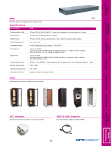
Fig. 1-1, PN-6x-T Generator and Enclosure (operator’s side)
1.0 System Overview
The AlphaGen PN-6x-T curb side generator system is designed to power outside plant
communication networks. Every AlphaGen system incorporates industry leading power technology,
including natural gas or propane fueling, exclusive audible noise baffl ing, remote status monitoring
features, and a durable, weather resistant enclosure.
The procedures in this document describe the installation, operation and maintenance of the PN-6x-T
generator and enclosure.
Features:
• Cost effective extended runtime solution for outdoor powering applications
• Quiet operation, small size, and low profi le allow for easier installation in populated areas
• Eliminates large quantities of batteries otherwise required for extended runtime
• Telecom grade 48VDC output
• Built-in safeguards to protect the system, operators and the public
• Safe unattended operation designed to UL2200, NFPA 37, 54, 58 & 70 standards

14
745-020-B0-003, Rev. C
Fig. 1-2, System Diagram
1.0 System Overview, continued
1.1 System Diagram
(See Fig. 3-12 for details)
SS
HR
SM
SR
STARTER RELAY
STM
F
UE
LP
2
-1
0
CRANK P2-1
7
1
IGNITION MODULE
IGNITION MODULE
7
0
G
ROUND P2-2
N
M4
P2-16
GAUGES P2-6
IG
NITI
O
NP2-1
3
IGN
P7-2
70
HR
M3
N
P
2
-1 2
P7-3
BAT
(
-) P
2
-3
-
SR
P
P
SS
P
+
STP
N
S
TT
O
VC
N
P
LOP
RUN
OV T
OV S
37
P1-6 START
P 1-9 S TOP
AC1
AC2
P3-4
P3-3
DCP
DCN
P3-2
P3-1
P7-4
THR OT TLE
P7-1
M1
P2-19
C
O
NTRO
L
M2
P
2
-2
0
3L
EA
D
ST
ATO
R
HIGH OIL TEM
P
SW
P
2-18
13
LO P
LOW OIL PRESSURE SWITCH
TB2-11
RECT
C
ARBU
R
E
T
OR
HEAT
E
R
120
V
AC
BLACK
RED
BA
TT
ER
Y
CH
A
RGER
J1
1
34
J2
2
1
2
1
J9
1
4
G
R
OUN D
EC
M
4
3
2
1
J
1
0
2
J9
T
B1
DOOR
O
P
E
N
NC
12 V
G
A
S
H
AZARD
P
O
WE
R
GAS HAZARD
PADSHEAR
LOW F U
E
LP
R
ESS.
5
4
6
2
8
7
3
13
12
11
1
0
T
B
2-8
ORANGE
YELLOW
9
TB
2
-7
WHI
TE
BLACK
2
BLAC
K
PADSH
EA
R
BLACK
RED
GREEN
O
RA
N
GE
1
123
AC SENSE
L
PG MODEL
ON
L
Y
2
1
2
00 AMP CB
T
B2-1
TB
2
-2
NC
NO
COM
L
TB 2
N
6
AC /
F
AI L
N
O
AC /
FA
IL
COM
AC
G
A
C
N
A
C
L
AC
/
F
A
IL
NC
345
2
1
LPG
(12V )
7
DOOR S W
G
A
S
HAZARD
SEN
S
O
R
OUT
P
UT
C
B
AUX S W
DOOR S
W
AL
A
RM
BYPA
S
S
REL
A
Y
7
6
8
1
NC
Do o
r
C
OM
12
D
oor
N
O
MI NOR
ALA
R
M
NO
COM
MI NOR
ALARM
NO
MI NOR
ALA
R
M
NC
ENG
RUN
NC
11
9
8
1
0
L
P
G
(-)
ENG
RU
N
NO
15
2
4
3
0
ECM
TB1
-
9
1
4
13
ECM
TB1
-6
E
C
M
T
B
1-
5
E
CM
T
B
1-
4
AL M
BY
C
O
M
AL
M
BY
NO
AL M
BY
NC
20
19
17
18
ALARM
C
O
M
ALA
RM
NO
MAJOR MAJOR MAJO
R
A
L
A
R
M
NC
MINOR
21
2223
IGNITION
BATTERY
QCON 1
HO
T
WHITE
WHI
T
E
1 WATER INTRUSION
YEL
RED
WHT
POS
NEG
LOW FUE
L
PRE
S
SURE SW
BLA
C
K
RED
1
6
ENG
RUN
COM
AC FAIL
R
EL
A
Y
BLOCK
H
EATER
P1-2 GROUND
P
3-5 BA
TT E
RY +
SE
N
SING
DC OU
TPU
T
NO
COM
30
SECONDS AFTER
SECOND SHUTDOWN
ENGINE
COMPA
R
TM
E
NT
START, THEN 5
INHIBIT FOR
P
1-12 OVER S
P
EE
D
P1-
7
L
OW O
I
L
PRESS.
SPEED SENSING
P1-10 ENGINE RUNNI NG
CONTROL
PCB
P1-
1
1
OVE
R
T
E
MP
.
P1-4 OVER CRANK
P1-1 GROUND
P1-3 BATTERY+
W
A
T
ER
I
N
TRU
SIO
N
1
2
3
4
5
6
7
8
9
1
0
11
12
P
2
-1
7
T
B
2
-13
NC
J4
N
C
12
11
3
1
1
6
3
10
2
4
8
7
5
9
TB 2- 20
Battery Charging
Regulator
BCA
A
C
D
B
E
+
-
ALARM
NC
COM

745-020-B0-003, Rev. C
15
Federal DOT Regulation 49 CFR Part 192.383, Excess Flow Valve Customer Notifi cation, requires gas
utilities to either voluntarily install Excess Flow Valves (EFVs) on all new home service lines or to notify
builders about EFVs’ benefi ts and availability. EFVs are installed on gas service lines during pre-construction
site work, and automatically activate when a gas line is ruptured. Excess fl ow valves should never be used as
in-line regulators. They cannot perform this function and may damage equipment.
Fig. 1-4, Excess Flow Valve
(above ground ¾" x 4" NPT nipple)
Alpha P/N 042-146-10
1.0 System Overview, continued
1.2 Natural Gas System Block Diagram
S
CONTROL
CONTROLS
ENGINE
Demand
Low-pressure
Regulator
14" WC
(max.)
WC = Water Column H
2
O
Pre-Regulator
Maxitrol 325-3
10 psi max input
Flare Coupling
(Quick-Disconnect)
NOTE: 1 psi = 28" WC
0.5 psi (min.)
1 psi (nominal)
10 psi (max)
Engine must have
7" to 11" WC and 156 cubic
feet/Hr. to operate
Solenoid
APU
Enclosure
Meter
Manual
Shutoff
Low pressure excess
flow valve (optional)
High pressure
excess flow valve
(optional)
For added safety, a low pressure and/or high pressure excess fl ow valve may be installed.
Do not include the generator system as part of a local gas piping system test. Damage to the
generator pre-regulator may result. The generator system is pressure tested in accordance with
NFPA standards prior to shipment.
Fig. 1-3, Arrangement of Metered, Nominal Pressure (1-2psi) Natural Gas System
NOTE:
ATTENTION:
CAUTION!

16
745-020-B0-003, Rev. C
Fig. 1-5, LP Propane Vapor Withdrawal Block Diagram
1.0 System Overview, continued
1.3 Liquid Propane System Block Diagram
DEMAND
REGULATOR
LOW PRESSURE
SOLENOI
D
8oz
ENGINE
LP PROPANE - VAPOR WITHDRAWAL
LOW FUEL
PRESSURE
S
CONTROL
CONTROLS
11"W
C
PROPANE
POST-REG
OUTLE
T
SENSOR
ENCLOSURE
APU
BLOCK DIAGRAM
SWITCH
PROPANE
ENCLOSURE
11"WC
MAX
LOW FUEL ALM
LPG TANK

745-020-B0-003, Rev. C
17
1.0 System Overview, continued
1.4 Specifi cations
System Specifi cations Specifi cation
System Size Height: 39.0" (57" with optional pedestal)
Width: 39.25"
Depth: 24"
Weight: 338 lbs (370 lbs with optional pedestal)
Acoustic 70.3 dBa @ 10 feet, (100% load)
DC Electrical Noise (PN-6x-T) RF: <100mV RMS in any 3kHz Band, 3kHz to
20MHz
Broadband: <250mV Pk to Pk
Voice Freq. Noise: Less than 56dBnrc
Gas Inlet Pressure 0.5-2 psi NOTE: Contact Alpha Technologies for
low pressure operation below 0.5 psi.
Integral Ignition Battery Charger Voltage 13.5 to 14.3VDC regulated, 15A max,
Remote Interface Length 12’ max. (sweep to sweep)
NOTE: Distance depends upon proper installation,
derating, and wire gauge. Contact Alpha Technolo-
gies for installations requiring greater distances.
Agency Compliance UL 1778, UL2200, CSA 22.2 No. 107.1, and appli-
cable sections of NFPA 37/54/58 and 70, EMC/FFC
Part 15 Class A
Exterior Surface Temperature 70°C max. (meets requirements of UL/CSA)
Fuel System Controls & Monitoring The controls and fuel system meet appropriate
sections of NFPA 37,54, and 58 for automatic,
unattended remote operation of enclosed
generators.
Sensors Gas Hazard, Pad Shear, Water Intrusion, Tamper,
Low Fuel Pressure
Safety Shutdowns Low oil shutdown
Oil over-temp
Engine over-speed
Over-crank (Crank limit)
Gas hazard (LPG or natural gas)
Low fuel pressure shutdown (LPG)
Water intrusion
Pad shear
Alternator over-voltage

18
745-020-B0-003, Rev. C
1.0 System Overview, continued
1.4 Specifi cations, continued
Generator Set
Specifi cation
48VDC
Manufacturer: Kohler
Dimensions (in/mm): 21.5"L x 20"W x 21.8"H/
546 x 508 x 554
Weight (lb/kg): 190/86
Rated* kW: 7.5
Rated Voltage
(after rectifi er):
52 ± 0.5VDC @ no load
Rated Amps: 144 @ 52VDC
* Derate approximately 4% per 1000 ft (300m) over
500 ft (153m) above sea level. Derate 1% for each
10ºF (5.5ºC) increase in temperature above 77ºF
(25ºC).
Generator
Specifi cations
48VDC
Stator Resistance
(ohms):
0.024
Stator Type: 3-phase, 3-lead,
ungrounded
Excitation Method: Permanent magnet,
brushless
Coupling Type: Direct-to-Engine
Insulation (stator): Class 180,
epoxy varnish,
vacuum-impregnated
Winding Material: Copper
Engine Specifi cations Specifi cation
Manufacturer Kohler
Make/model CH20
Cycle 4
Compression Ratio 8:5:1
Displacement, cu. in. (cc) 38 (624)
Rated Horsepower
(using natural gas fuel)
13.1
Engine Speed (rpm): 2100-3450
Bore, in. (mm) 3.08 (77)
Stroke, in. (mm) 2.64 (67)
Valve Train Overhead valve
Valve Material:
Intake
Exhaust
Steel
Stellite
®
face
Number of Cylinders 2
Cylinder Block Material Aluminum with cast iron liners
Cylinder Head Material Aluminum
Cylinder Head Tightening Torque, ft.
lb (Nm)
30 (41)
Piston Rings 2 compression, 1 oil
Crankshaft Material Heat treated, ductile iron casting
Bearings:
Number
Type
2
Replaceable sleeve
Governor Electronic
Starter Motor Electric, 12VDC, solenoid shift
Lubrication System Full pressure
Oil Capacity
(with fi lter and cooler), qt. (L) 2 (1.9 )
Oil Filter Tightening Torque 1/2 turn
Oil Pressure, psi (kPa) 25-35 (172-241)
Low Oil Pressure, psi (kPa) 3.5±1.5 (24.1±13.8)
Fuel Type Natural gas or propane
Fuel Pressure, kPA (in. water) 7-11 (1.7-2.7)
Fuel Consumption at 7.5kW:
Natural Gas, 1000 BTU/ft.
3
Propane, 2516 BTU/ft.
3
150 cfh
50 cfh
Battery Voltage 12VDC
Battery Ground Negative
Battery Recommendation (min.) 585 CCA @ 0ºF ( -18ºC)
Spark Plug Type
(Kohler P/N 24 132 02-S):
(Champion RC12YC)
Spark Plug Gap, in. (mm) 0.030 (0.75)
Spark Plug Tightening Torque, ft. lb
(Nm)
18-22 (24.4-29.8)
Ignition System Capacitive discharge
Cooling System Air cooled
High Engine Temperature, ºF (ºC) 305 (152)

745-020-B0-003, Rev. C
19
2.0 Site Preparation
2.1 Site Considerations
• Where possible, select a site that is above the 100 year fl ood plain, and away from
houses.
• Place in a shaded location to minimize the effects of solar loading.
• Avoid locating the enclosure where it is an obstruction and would inhibit visibility.
• Locate the enclosure away from sprinkler systems or other sources of forced water.
• Locate the enclosure out of the prevailing wind to minimize the buildup of snow or the
accumulation of wind-borne dust.
• Determine if soil conditions are suitable for the installation of the applicable required
grounding system.
• Verify utility power cabling has been run and terminated at the site.
2.2 Acoustics
Nuisance noise is of concern to nearby residents. Nuisance noise is a directional noise
which can cause discomfort during engine-generator operation to nearby residential
occupants (audible levels may vary due to absorption and refl ection caused by the immediate
surroundings).
Audible impact on neighborhoods is mitigated by recent advances in muffl ers, fl ame resistant
sound materials, intake air sound attenuators, along with improved cabinet airfl ow dynamics.
The fi gures below show the measured audible levels from PN-6x-T 7.5kW generator at full
load. Note the symmetry of these emissions. Deployment decisions must include noise
consideration. The elimination of nuisance noise, and the reduction of directional impact
within a residential community, is critical.
Fig. 2-1, Generator Sound Levels at 100% Load
10'
20'
50'
70.3
64.3
56.3
dBa
Feet

20
745-020-B0-003, Rev. C
Fig. 2-2, Acoustical Measurements in Relation to Placement Near Residences
(generator sound levels at full load)
2.0 Site Preparation, continued
2.2 Acoustics, continued
The design of the engine-generator system should direct a majority of the operational noise
toward the street and away from residences that may be located behind the curb side system.
This strategic cabinet design and placement within the community can minimize nuisance
noise and city ordinance issues.
House
Engine-Generator
House
Street
20 Feet, (64 dBa)
50 Feet (56 dBa)
Page is loading ...
Page is loading ...
Page is loading ...
Page is loading ...
Page is loading ...
Page is loading ...
Page is loading ...
Page is loading ...
Page is loading ...
Page is loading ...
Page is loading ...
Page is loading ...
Page is loading ...
Page is loading ...
Page is loading ...
Page is loading ...
Page is loading ...
Page is loading ...
Page is loading ...
Page is loading ...
Page is loading ...
Page is loading ...
Page is loading ...
Page is loading ...
Page is loading ...
Page is loading ...
Page is loading ...
Page is loading ...
Page is loading ...
Page is loading ...
Page is loading ...
Page is loading ...
Page is loading ...
Page is loading ...
Page is loading ...
Page is loading ...
Page is loading ...
Page is loading ...
Page is loading ...
Page is loading ...
Page is loading ...
Page is loading ...
Page is loading ...
Page is loading ...
Page is loading ...
Page is loading ...
Page is loading ...
Page is loading ...
Page is loading ...
Page is loading ...
Page is loading ...
Page is loading ...
Page is loading ...
Page is loading ...
Page is loading ...
Page is loading ...
Page is loading ...
Page is loading ...
Page is loading ...
/