DKS MicroCLICK 8059 User manual

Category
Security device components
Type
User manual

This manual is also suitable for

Installation
Receiver Terminal Wiring
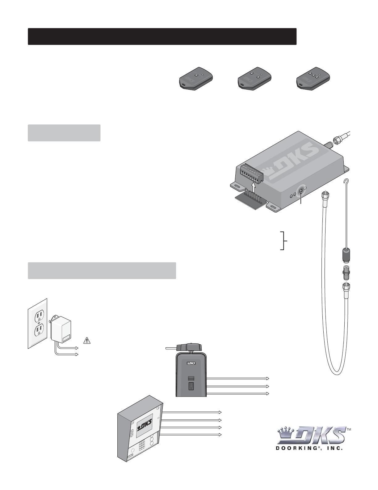
DoorKing Part Number
This receiver is NOT designed to be installed outdoors without being protected
from the weather. An outdoor enclosure is available for the receiver if required
(P/N 8057-110 - Metal Outdoor Box).
Install the 8059 receiver in a location so the antenna is NOT surrounded by
metal and is in free air as high as possible above the ground. A longer Coax
Antenna kit is available for the receiver if required (P/N 1514-073 - Includes
antenna, mounting “L” bracket and 15 feet of coax cable). An antenna amplifier
kit (P/N 8058-080) or a Yagi directional antenna kit (P/N 1514-072) is also
available for the receiver if required.
The Programming LED on the side of the case will blink as RF energy is
received. If the programming LED blinks or is on continuously, this
indicates that there may be interference on the frequency (318 MHz) and
short range may be the result. If this happens, try relocating the receiver
or remove the source of interference. An antenna amplifier or a
directional antenna may be needed. Note: Loop detectors and proximity
card readers can cause receiver interference.
120 Glasgow Avenue
Inglewood, California 90301
U.S.A.
To Receiver Terminal #1 (Neg.)
To Receiver Terminal #2 (Pos.)
12-24 Volt
Transformer
DC Polarity Matters!
Removable
receiver terminal
for easy wiring.
Be sure the antenna, coax shield
and F connector are completely
isolated from the ground.
8059-080
80 Transmitter Codes
Stand-Alone Power and Device Wiring : Connect 12 - 24 Volt AC or DC power to
terminals #1 and #2. Use minimum 18 AWG wire to power the receiver.
If DC power is used (Transformer): Terminal #1 is NEGATIVE and Terminal #2 is POSITIVE.
Connect the receiver relay contacts to the device to be activated.
- Receiver Terminal #3 is the relay contact Normally OPEN (N.O.)
- Receiver Terminal #4 is the relay contact Normally CLOSED (N.C.)
- Receiver Terminal #5 is the relay contact Common (C).
Wiegand Controller Wiring:
Receiver terminal #2 is INPUT POWER (12-24 V).
Receiver terminal #6 is Wiegand input power COMMON.
Receiver terminal #7 is Wiegand DATA 0.
Receiver terminal #8 is Wiegand DATA 1.
Use 22 AWG shielded wire, maximum
200 feet, for Wiegand controller wiring.
Connect these terminals to the
corresponding terminals on
the Wiegand controller. Refer to the
DoorKing Wiegand controller installa-
tion manual 1835, 1837 or 1838 for
specific wiring information.
#1 - Input Power Common (Negative)
#2 - Input Power 12-24 Volt AC, 12-24 Volt DC (Positive)
#3 - Relay Contact (Normally Open)
#4 - Relay Contact (Normally Closed)
#5 - Relay Contact (Common)
#6 - Wiegand Common
#7 - Wiegand Data 0
#8 - Wiegand Data 1
1
2
3
4
5
6
7
8
Programming LED
F Connector
Coax
Antenna
Kit
(Included)
18”
Coax
Cable
Terminals 3-4-5
rated for 30 volt,
1 amp max.
From “Low Voltage Common”
From “Radio Open”
From “Circuit Board” Power
Stand-Alone Gate Operator: Connect the 3
wires from the gate operator as indicated. Refer
to the chosen gate operator’s installation/owner’s
manual for specific wiring information.
To Receiver Terminal #1
To Receiver Terminal #2
To Receiver Terminal #3
From “Low Voltage Common”
From “Data 1”
From “Data 0”
From “Circuit Board” Power
To Receiver Terminal #2
To Receiver Terminal #6
To Receiver Terminal #7
To Receiver Terminal #8
Receiver
Terminal
MODEL 8059 MicroCLIK
RF RECEIVER (WIEGAND)
The model 8059 RF Receiver is designed for use as a Stand-Alone or Wiegand applications using MicroCLIK™ transmitters. Stand-Alone installa-
tions can store up to 80 transmitter codes in its memory. It is also programmed to recognize only certain MicroCLIK™ transmitter buttons when
using multiple button transmitters.
The 8059 receiver activates a built-in dry contact form “C” relay
when a programmed MicroCLIK™ transmitter code is received.
The received code MUST match the programmed “Transmitter
Code”, “Facility Code” (or not match the Facility Code if a
Wiegand controller is used), and “Transmitter Button Code”
before the receiver relay will activate.
Wiegand applications will output transmitter codes in 26-bit or 31-bit Wiegand format to an external Wiegand controller.
The MicroCLIK™ system is compatible with the HomeLink system found in many automobiles.
P/N 8066-080 P/N 8067-080 P/N 8068-080
1
Butto
n
2
Butto
n
3
Butto
n
MicroCLIK™ Transmitters
1837
How Receiver Functions
1. Regular Transmitter Programming
120 Glasgow Avenue
Inglewood, California 90301
U.S.A.
1
2
3
4
5
6
7
8
Programming Button
Press and hold the Programming Button or the “Master Transmitter Button” (if existing, see above) until the programming LED quickly flashes ONE
time (about 2 seconds), then release the button. The programming LED will flash once every second indicating that you are in the transmitter
programming mode....
....While the programming LED is flashing, activate each of the MicroCLIK™ transmitters that will be used (If you are using a two or three button
transmitter, make sure to press the correct button). There are three (3) different “2-Button” MicroCLIK
transmitter button combinations that each
receiver can be programmed to respond to: button-1, button-2 and buttons 1&2 pressed at the same time. There are six (6) different “3-Button”
MicroCLIK
transmitter button combinations that each receiver can be programmed to respond to: button-1, button-2, button-3, buttons 1&2
pressed at the same time, buttons 2&3 pressed at the same time and buttons 1&3 pressed at the same time. A maximum of 80 transmitters codes
can be stored in this receiver. Each button or combination of buttons pressed is counted as ONE transmitter code.
Once the desired transmitter codes have been stored into the receiver memory, the receiver will automatically exit the programming mode when no
more transmitter codes are received (approx. 10 seconds idle time). The LED will come on for 3 seconds and then go out.
Release
Button
One Quick Flash
2 Sec.
Press and
Hold Button
1 Sec. 1 Sec. 1 Sec. 1 Sec. 1 Sec.
Transmitter Programming Mode
Activate All Desired
MicroCLIK™ Transmitters
All Desired
MicroCLIK™ Transmitters
have been Activated
1 Sec. 1 Sec. 1 Sec. 1 Sec.
Transmitter Programming Mode
Approximately 10 Seconds Idle Time
Less than 10 Seconds Idle Time
FINISH
START
There are seven receiver programming functions:
1. Regular Transmitter Programming
2. 26-bit Wiegand Programming (Factory Setting)
3. 31-bit Wiegand Programming
Wiegand LED’s: Will blink
as Wiegand data is being
transmitted.
Programming LED: Will
flash sequences during
programming and
flashes during normal
operation or frequency
interference.
4. Match Facility Code Programming
5. Ignore Facility Code Programming
6. Erase ALL Transmitter Codes
7. Master Transmitter Programming
The 8059 receiver responds to the MicroCLIK™ transmitter code is defined by “Facility Codes”
and “Transmitter Button Codes”. For example: an 8059 receiver can be programmed to
respond to only the first button on a multiple button MicroCLIK™ transmitter while a
second 8059 receiver can be programmed to respond to only the second button of
the same multiple button MicroCLIK™ transmitter. Thus allowing a single multiple
button MicroCLIK™ transmitter to activate two different receivers without fear of
both receivers responding to the same transmitter code. Like wise one receiver
can be programmed to respond to a specific facility code while another can be
programmed for a different facility code. In Wiegand output mode, you have the
option of matching or ignoring the facility code to allow the receiver to activate.
One
3 Second
Flash
The receiver is now in
26-bit Wiegand Output Mode
2. 26-bit Wiegand Programming
When Using Wiegand Functions
Press and hold the Programming Button and follow the flashing LED sequence as shown below, then release the button. The programming LED
will flash once for 3 seconds indicating that the receiver is in 26-bit Wiegand output mode.
At least one transmitter code must be programmed into the receiver memory, allowing the receiver to respond to the facility code and transmitter
button code that will be used. This step is necessary so that the receiver knows which transmitter button to respond to. For example, if a (2) two
button transmitter code is programmed into the receiver pressing only button-2, the receiver will only respond to transmitter codes initiated by
button-2. To have a receiver respond to both buttons, you can program the transmitter code into the receiver twice, using button-1 first, and then
button-2. If using more than one facility code or if the receiver is to respond to different transmitter buttons, simply add additional transmitters,
refer to 1. Regular Transmitter Programming. The receiver will allow the facility code to be ignored when using a Wiegand controller if desired.
One 3 Second
Flash
Release
Button
Press and
Hold Button
Approximately 4 Sec.
Two
One Flash
Six
8059-065-G-3-12
Copyright 2012 DoorKing, Inc. All rights reserved.
120 Glasgow Avenue
Inglewood, California 90301
U.S.A.
The receiver is now in
31-bit Wiegand Output Mode
3. 31-bit Wiegand Programming
Press and hold the Programming Button and follow the flashing LED sequence as shown below, then release the button. The programming LED
will flash once for 3 seconds indicating that the receiver is in 31-bit Wiegand output mode.
One 3 Second
Flash
Release
Button
Press and
Hold Button
Press and
Hold Button
Press and
Hold Button
Press and
Hold Button
Approximately 6 Seconds
Two Three
One Flash
The receiver will check
facility code for a match
4. Match Facility Code Programming
Press and hold the Programming Button and follow the flashing LED sequence as shown below, then release the button. The programming LED
will flash once for 3 seconds indicating the receiver will check the facility code for a match before outputting the transmitter code.
One 3 Second
Flash
Release
Button
Approximately 10 Seconds
Four FiveTwo Three
Three Times in a Row
One Flash
F
F
F
Fi
Fi
i
i
FourFour
T
T
The receiver will ignore
the facility code
ALL transmitters
will now be erased
5. Ignore Facility Code Programming
Press and hold the Programming Button and follow the flashing LED sequence as shown below, then release the button. The programming LED
will flash once for 3 seconds indicating the receiver will ignore the facility code.
One 3 Second
Flash
Release
Button
Approximately 12 Seconds
Four FiveTwo Three
Three Times in a Row
One Flash
F
F
Fi
Fi
i
i
FourFour
T
T
6. Erase ALL Transmitter Codes
When memory is full, a long flash will activate when trying to program a new transmitter. To erase memory, press and hold the Programming
Button and follow the flashing LED sequence as shown below, then release the button. This will erase ALL regular and master transmitter codes.
FourTwo Three
Three Times in a Row
One Flash
F
F
FourFour
T
T
WARNING: Deleted transmitter
codes CANNOT be retrieved.
Release
Button
The 8059 receiver “Master Transmitter Programming” will allow you to program up to (4) four master transmitters for easy future transmitter
additions if desired. When a “Master Transmitter” is activated, the 8059 receiver will AUTOMATICALLY go into “Learn Mode” allowing additional
transmitters to be programmed into the receiver memory without having to go through the normal “Regular Transmitter Programming” process
(See below). This is an easier way to add additional transmitters to the receiver’s memory in the future. Master transmitters are NOT required to
program regular transmitters. They are NOT intended to be used as regular transmitters and should be kept in a safe place.
Four Five
7. Master Transmitter Programming
After getting into the master programming mode, select a transmitter to designate as a Master Transmitter and press
the transmitter button. This process can be done with up to 3 additional transmitters if desired, The transmitter code,
facility code and transmitter button code from the transmitter(s) are programmed into the receiver as a Master
Transmitter(s). The receiver will automatically exit the programming mode when no more transmitter codes are
received (approx. 10 seconds idle time). These 3 codes must match the master transmitter’s 3 codes in order to put
the receiver automatically back into the “Learn Mode” when adding additional transmitters in the future.
Two Three
Three Times in a Row
One Flash
Press and Hold
Programming
Button
Release
Button
F
F
F
Fi
Fi
i
i
FourFour
T
T
EightSevenSix
S
S
S
S
S
You are now in Master
Programming Mode
  • Page 1 1
  • Page 2 2
  • Page 3 3

DKS MicroCLICK 8059 User manual

Category
Security device components
Type
User manual
This manual is also suitable for

Ask a question and I''ll find the answer in the document

Finding information in a document is now easier with AI