
D-ILA™ PROJECTOR
80
VERSION 1.0
OWNER’S OPERATING MANUAL

2
Introduction ............................................................................ 3
Contents of the package .................................................................. 3
Options: .................................................................................................. 3
Safety Precautions .................................................................. 4
About Burning-in of D-ILA Device ...................................................7
Viewing Conditions (Brightness of Room) ...................................7
Environment of Use ..............................................................................7
Maintenance Procedures ....................................................................7
Warranty .................................................................................. 8
Controls and Features .......................................................... 10
Projector Chassis Cover .................................................................... 10
Connector Panel .................................................................................11
Indicator Display on the Control Panel .......................................13
Remote Control ................................................................................... 14
Installing the Projector ........................................................ 15
Precautions for Installation .............................................................15
Installation Environment ................................................................. 15
Minimum Space Required ............................................................... 15
Precaution for Usage .........................................................................15
Projector and Screen Installation .................................................. 16
Mounting the Unit on a Ceiling ...................................................16
Screen Size and Projection Distance ........................................17
Throw Distance Chart .....................................................................17
Eff ective Range of Remote Control Unit .................................... 18
Connecting to Various Devices ............................................ 19
Connecting to Devices ..................................................................... 19
Connecting to the VDP-80 digital video processor .............19
Control from an external automation device .........................19
Connecting the Power Cord (supplied) ......................................20
Basic Operation .................................................................... 21
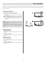
Turning on the power ....................................................................... 21
Adjusting Zoom .................................................................................. 21
Adjusting Focus ................................................................................... 21
Hiding the image temporarily ....................................................... 22
Turning on the power ....................................................................... 22
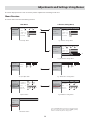
Adjustments and Settings Using Menus ............................. 23
Menu Structure ................................................................................... 23
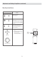
Menu Operation Buttons .................................................................24
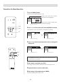
Procedures for Menu Operation ................................................... 25
Screen Blanking .................................................................... 27
V Shift Setting ....................................................................... 28
Replacing the Lamp (For service personnel only) .............. 29
Lamp and Lamp Usage Time .......................................................... 29
Resetting Lamp Time ........................................................................ 29
Cleaning and Replacing the Filter ....................................... 30
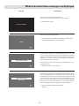
What to do when these messages are displayed ............... 31
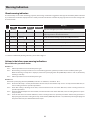
Warning Indication ............................................................... 32
About warning indicators ................................................................ 32
Actions to be taken upon warning indications ....................... 32
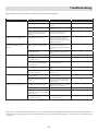
Troubleshooting ................................................................... 33
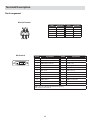
Terminal Description ............................................................ 34
Pin Arrangement ................................................................................ 34
RS-232C External Control .................................................................35
Communication Specifi cations ...................................................35
Command Format ............................................................................35
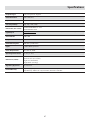
Specifi cations ........................................................................ 37
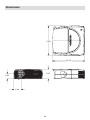
Dimensions ........................................................................... 38
Table of Contents
Accessories
The following accessories are packed together with this unit. Please confi rm all items.
If any item is missing, please contact your dealer.
Instruction Manual x 1
Warranty x 1
Power Cord x 1
Remote Control x 1
AAA size Batteries (for operation confi rmation) x 2

3
Thank you for purchasing the Vidikron Vision Model 80 projector and welcome to the Vidikron family. With proper setup and use, this prod-
uct will bring you many years of enjoyment.
Introduction to the Vidikron Vision Model 80 D-ILA™ Projector
Vidikron presents the highest resolution home theater video available today. The Vision™ Model 80 employs advanced D-ILA™ (Direct Drive
Image Light Amplifi er) technology and boasts a native resolution of 1920 x 1080 – over six million pixels.
This exciting technology is capable of producing the most natural, smooth images available in digital projection. Tremendous detail, richly
saturated colors and outstanding black level reproduction are hallmarks of the Model 80.
Vidikron’s incorporation of three D-ILA chips result in exceptionally low noise without the fl icker and “rainbow eff ect” that often plague
one-chip digital video display devices. Vidikron engineers have also paid careful attention to accurate gray scale tracking and true 6500K
color reproduction capability. Together, all of these engineering achievements produce the most pleasing and fi lm-like high resolution
pictures imaginable.
With 1050 ANSI lumens of light output (CSMS™ Light Output of 18.1 ft-Lamberts) and a 2100:1 contrast ratio, the Model 80 off ers state-
of-the-art picture quality on screens as large as eight feet wide. Vidikron’s exclusive Imagix™ video processing is featured in a separate
outboard controller/processor that scales signals from 480i to 1080i to the Model 80’s native1080p resolution, transforming any source
into stunning high defi nition resolution.
In addition, Vidikron’s discrete multiple aspect ratio control, as well as discrete IR and RS-232 control make custom installation seamless,
while discrete source selection accommodates any automation control system.
Introduction
The Features You’ll enjoy include:
• Ultra High Resolution D-ILATM Technology for Pristine
Video Images
• 3-Chip D-ILA Confi guration with Native 16:9 Aspect Ratio
• 1920 x 1080 Native Resolution — Over 6 Million Pixels
• Vidikron’s Exclusive Imagix™ Video Processing with Separate
Controller/Processor for Outstanding Image Fidelity
• 1050 ANSI Lumens /CSMSTM Light Output of 18.1 ft-Lamberts
• 2100:1 Contrast Ratio
• Discrete Aspect Ratio and Source Selection
• DVI Input with HDCP• Discrete IR and RS-232 Control
Contents of the package
• 3-Chip Projection System
• (1) AC Power cord
• (1) AV connection cable
• (1) Remote controll with (2) AA batteries
• (1) Screen trigger terminal cable
• (1) User’s manual
• (1) Warranty information and registration card
Options:
• Ceiling mount unit

4
Safety Precautions
NOTICE (For USA)
Language for Manuals of Products using HID Lamps (that contains mer-
cury)
This product has a High Intensity Discharge (HID) lamp that contains
a small amount of mercury. It also contains lead in some compo-
nents.
Disposal of these materials may be regulated in your community due
to environmental considerations. For disposal or recycling informa-
tion please contact your local authorities, or the Electronics Indus-
tries Alliance: http:// www.eiae.org.
WARNING:
TO PREVENT FIRE OR SHOCK HAZARDS, DO NOT EXPOSE THIS APPLI-
ANCETO RAIN OR MOISTURE.
WARNING:
THIS APPARATUS MUST BE GROUNDED.
CAUTION:
To reduce the risk of electric shock, do not remove cover. Refer servic-
ing to qualifi ed service personnel.
This projector is equipped with a 3-blade grounding type plug to
satisfy FCC rule. If you are unable to insert the plug into the outlet,
contact your electrician.
FCC INFORMATION (U.S.A. only)
CAUTION:
Changes or modifi cation not approved by JVC could void the user’s
authority to operate the equipment.
NOTE:
This equipment has been tested and found to comply with the lim-
its for Class B digital devices, pursuant to Part 15 of the FCC Rules.
These limits are designed to provide reasonable protection against
harmful interference in a residential installation. This equipment
generates, uses, and can radiate radio frequency energy and, if not
installed and used in accordance with the instructions, may cause
harmful interference to radio communications. However, there is no
guarantee that interference will not occur in a particular installation.
If this equipment does cause harmful interference to radio or televi-
sion reception, which can be determined by turning the equipment
off and on, the user is encourage to try to correct the interference by
one or more of the following measures:
• Reorient or relocate the receiving antenna.
• Increase the separation between the equipment and receiver.
• Connect the equipment into an outlet on a circuit diff erent from
that to which the receiver is connected.
• Consult the dealer or an experienced radio/TV technician for help.
MACHINE NOISE INFORMATION (Germany only)
Changes Machine Noise Information Ordinance 3. GSGV, January 18,
1991: The sound pressure level at the operator position is equal or
less than 70 dB (A) according to ISO 7779.
About burning-in of the D-ILA device
Do not allow the same still picture to be projected for a long time or
an abnormally bright video picture to be projected. Do not project
video images with high-intensity or high contrast on a screen. The
video image could be burnt into the D-ILA device. Use special care
when projecting video games or computer program images.There
is no problem with ordinary video-cassette playback images.
About the installation place
Do not install the projector in a place that cannot support its weight
securely. If the installation place is not sturdy enough, the projector
could fall or overturn, possibly causing personal injury.
IMPORTANT SAFEGUARDS
Electrical energy can perform many useful functions. This unit has
been engineered and manufactured to assure your personal safety.
But IMPROPER USE CAN RESULT IN POTENTIAL ELECTRICAL
SHOCK OR FIRE HAZARD. In order not to defeat the safeguards
incorporated into this product, observe the following basic rules for
its installation, use and service. Please read these Important Safe-
guards carefully before use.
– All the safety and operating instructions should be read before
the product is operated.
– The safety and operating instructions should be retained for fu-
ture reference.
– All warnings on the product and in the operating instructions
should be adhered to.
– All operating instructions should be followed.
– Place the projector near a wall outlet where the plug can be easily
unplugged.
– Unplug this product from the wall outlet before cleaning. Do not
use liquid cleaners or aerosol cleaners. Use a damp cloth for clean-
ing.
– Do not use attachments not recommended by the product manu-
facturer as they may be hazardous.
– Do not use this product near water. Do not use immediately af-
ter moving from a low temperature to high temperature, as this
causes condensation, which may result in fi re, electric shock, or
other hazards.
– Do not place this product on an unstable cart, stand, or table. The
product may fall, causing serious injury to a child or adult, and
serious damage to the product. The product should be mounted
according to the manufacturer’s instructions, and should use a
mount recommended by the manufacturer. (symbol provided by
RETAC)
– When the product is used on a cart, care should be taken to avoid
quick stops, excessive force, and uneven surfaces which may
cause the product and cart to overturn, damaging equipment or
causing possible injury to the operator.

5
– Slots and openings in the cabinet are provided for ventilation.
These ensure reliable operation of the product and protect it from
overheating.These openings must not be blocked or covered.
(The openings should never be blocked by placing the product
on bed, sofa, rug, or similar surface. It should not be placed in a
built-in installation such as a bookcase or rack unless proper ven-
tilation is provided and the manufacturer’s instructions have been
adhered to.) For proper ventilation, separate the product from
other equipment, which may prevent ventilation and keep a dis-
tance of more than 11-7/8” (30 cm).
– This product should be operated only with the type of power
source indicated on the label. If you are not sure of the type of
power supply to your home, consult your product dealer or local
power company.
– This product is equipped with a three-wire plug. This plug will fi t
only into a grounded power outlet. If you are unable to insert the
plug into the outlet, contact your electrician to install the proper
outlet. Do not defeat the safety purpose of the grounded plug.
– Power-supply cords should be routed so that they are not likely to
be walked on or pinched by items placed upon or against them.
Pay particular attention to cords at doors, plugs, receptacles, and
the point where they exit from the product.
– For added protection of this product during a lightning storm, or
when it is left unattended and unused for long periods of time,
unplug it from the wall outlet and disconnect the cable system.
This will prevent damage to the product due to lightning and
power line surges.
– Do not overload wall outlets, extension cords, or convenience re-
ceptacles on other equipment as this can result in a risk of fi re or
electric shock.
– Never push objects of any kind into this product through open-
ings as they may touch dangerous voltage points or short out
parts that could result in a fi re or electric shock. Never spill liquid
of any kind on the product.
– Do not attempt to service this product yourself as opening or re-
moving covers may expose you to dangerous voltages and other
hazards. Refer all service to qualifi ed service personnel.
– Unplug this product from the wall outlet and refer service to qual-
ifi ed service personnel under the following conditions:
a) When the power supply cord or plug is damaged.
b) If liquid has been spilled, or objects have fallen on the product.
c) If the product has been exposed to rain or water.
d) If the product does not operate normally by following the op-
erating instructions. Adjust only those controls that are covered
by the Operation Manual, as an improper adjustment of controls
may result in damage and will often require extensive work by a
qualifi ed technician to restore the product to normal operation.
e) If the product has been dropped or damaged in any way.
f ) When the product exhibits a distinct change in performance- this
indicates a need for service.
– When replacement parts are required, be sure the service techni-
cian has used replacement parts specifi ed by the manufacturer or
with same characteristics as the original part. Unauthorized sub-
stitutions may result in fi re, electric shock, or other hazards.
– Upon completion of any service or repairs to this product, ask the
service technician to perform safety checks to determine that the
product is in proper operating condition.
– The product should be placed more than one foot away from heat
sources such as radiators, heat registers, stoves, and other prod-
ucts (including amplifi ers) that produce heat.
– When connecting other products such as VCR’s, and personal
computers, you should turn off the power of this product for pro-
tection against electric shock.
– Do not place combustibles behind the cooling fan. For example,
cloth, paper, matches, aerosol cans or gas lighters that present
special hazards when over heated.
– Do not look into the projection lens while the illumination lamp is
turned on. Exposure of your eyes to the strong light can result in
impaired eyesight.
– Do not look into the inside of this unit through vents (ventilation
holes), etc. Do not look at the illumination lamp directly by open-
ing the cabinet while the illumination lamp is turned on. The il-
lumination lamp also contains ultraviolet rays and the light is so
powerful that your eyesight can be impaired.
– Do not drop, hit, or damage the light-source lamp (lamp unit) in
any way. It may cause the light-source lamp to break and lead
to injuries. Do not use a damaged light source lamp. If the light-
source lamp is broken, ask your dealer to repair it. Fragments from
a broken light-source lamp may cause injuries.
– The light-source lamp used in this projector is a high pressure mer-
cury lamp. Be careful when disposing of the light-source lamp. If
anything is unclear, please consult your dealer.
– Do not ceiling-mount the projector to a place which tends to vi-
brate; otherwise, the attaching fi xture of the projector could be
broken by the vibration, possibly causing it to fall or overturn,
which could lead to personal injury.
– Use only the accessory cord designed for this product to prevent
shock. The power supply voltage rating of this product is AC 120 V,
AC 100 V – AC 240 V, the power cord attached conforms to the fol-
lowing power supply voltage. Use only the power cord designated
by our dealer to ensure Safety and EMC. When it is used by other
power supply voltage, power cable must be changed. Ensure that
the power cable used for the projector is the correct type for the
AC outlet in your country. Consult your product dealer.
Power supply voltage: AC 120 V
Power cord
*DO NOT allow any unqualifi ed person to install the unit.
Be sure to ask your Vidikron dealer to install the unit (e.g. attach-
ing it to the ceiling) since special technical knowledge and skills
are required for installation.
If installation is performed by an unqualifi ed person, it may cause
personal injury or electrical shock.

6
Safety Precautions (continued)
WARNING:
Do not cut off the main plug from this equipment. If the plug
fi tted is not suitable for the power points in your home or the
cable is too short to reach a power point, then obtain an appro-
priate safety approved extension lead or adapter or consult your
dealer.
If, nonetheless, the main plug is cut off , remove the fuse and dis-
pose of the plug immediately, to avoid a possible shock hazard
by inadvertent connection to the main supply. If a new main plug
has to be fi tted, then follow the instructions given below.
WARNING:
THIS APPARATUS MUST BE GROUNDED. IMPORTANT:
The wires in the mains lead on this product are colored in accor-
dance with the following cord:
Green-and-yellow : Earth
Blue : Neutral
Brown : Live
As these colors may not correspond with the colored markings
identifying the terminals in your plug, proceed as follows:
The wire which is colored green-and-yellow must be connected to
the terminal which is marked with the letter E or the safety earth
or colored green or green-and-yellow. The wire which is colored
blue must be connected to the terminal which is marked with the
letter N or colored black. The wire which is colored brown must
be connected to the terminal which is marked with the letter L or
colored red. When replacing the fuse, be sure to use only a cor-
rectly rated approved type, re-fi t the fuse cover.
IF IN DOUBT — CONSULT A COMPETENT ELECTRICIAN.

7
About Burning-in of D-ILA Device
• Do not allow the same still picture to be projected for a long
time or an abnormally bright video image to be projected.
Do not project video images with a high intensity or high contrast
on a screen. This video image could be burnt into this D-ILA de-
vice. Pay special attention when projecting video games and com-
puter program images. There is no problem with ordinary video
cassette, DVD or TV playback images.
Viewing Conditions (Brightness of Room)
• Brightness of the room
Avoid direct exposure of screen to direct sunlight and illumina-
tion. Block light using a curtain. Images can be well projected by
darkening the brightness of the room.
• Do not view screen for prolonged hours
Looking at the screen continually for a prolonged time will cause
your eyes to get tired. Allow your eyes to rest at intervals.
• Do not use this unit when image fl ickers due to installation condi-
tions and environment.
This may cause your eyesight to deteriorate.
Environment of Use
• Do not use this unit in rooms with cigarette smoke
Do not use this unit in rooms with cigarette smoke. This may cause
the unit to malfunction.
• When mounting this unit to ceiling
Check temperature around the unit.
When a heater is in use, the ceiling may reach a temperature high-
er than anticipated, leading to malfunction of the unit.
Maintenance Procedures
• Clean dirt on the cabinet with a soft cloth.
In case of heavy soiling, soak a cloth in neutral detergent diluted
with water, wring dry and wipe, followed by wiping again using a
dry cloth.
• Pay attention to the following as the cabinet may deteriorate
in condition, get damaged or paint may come off .
• Do not wipe with a stiff cloth
• Do not wipe with force
• Do not wipe with thinner or benzene
• Do not spray volatile chemicals like insecticide
• Do not allow prolonged contact with rubber or plastic products
• Dirt on the lens should be cleaned using using commercial blow-
ers or lens cleaning papers (for cleaning glasses and cameras). Do
not use fl uid type cleaning agents. This may lead to peeling of
the surface coating fi lm. Lens surface is fragile. Avoid rubbing or
knocking it.
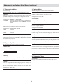
There are replacement components required for maintenance of the functions of this product such as optical components, cooling fan
and fi lters. Life span of components varies considerably with the frequency of use and environment in which they are used. For replace-
ment of components (except fi lters), please consult your authorized dealer.
Standard for gauging replacement time of components

8
Congratulations on your purchase of a Vidikron video product and welcome to the Vidikron family! With proper
installation, setup and care, you should enjoy many years of unparalleled video performance.
This is a LIMITED WARRANTY as defined in the Magnuson-Moss Warranty Act. Please read it carefully and retain it with
your other important documents.
WHAT IS COVERED UNDER THE TERMS OF THIS LIMITED WARRANTY:
SERVICE LABOR: Vidikron will pay for service labor by a Vidikron Authorized Service Center when needed as a result
of manufacturing defect for a period of two (2) years from the eff ective date of delivery to the end user (excluding the
lamp).
PARTS: (Not including the lamp) Vidikron will provide new or rebuilt replacement parts for the parts that fail due to
defects in materials or workmanship for a period of two (2) years from the eff ective date of delivery to the end user. Such
replacement parts are then subsequently warranted for the remaining portion (if any) of the original warranty period.
PROJECTOR LAMP: Vidikron will pay for service labor by a Vidikron Authorized Service Center when needed as a result
of a manufacturing defect for a period of six (6) months or 1000 hours, which ever comes fi rst, from the eff ective date
of delivery to the end user. In addition, Vidikron will provide a new or rebuilt replacement lamp for the lamp that fails
due to defects in materials or workmanship for a period of six (6) months or 1000 hours, which ever comes fi rst, from the
eff ective date of delivery to the end user. Such replacement lamps are then subsequently warranted for the remaining
portion (if any) of the original warranty period.
WHAT IS NOT COVERED UNDER THE TERMS OF THIS LIMITED WARRANTY:
This Limited Warranty only covers failure due to defects in materials and workmanship that occur during normal use
and does not cover normal maintenance. This Limited Warranty does not cover cabinets or any appearance items; failure
resulting from accident, misuse, abuse, neglect, mishandling, misapplication, faulty or improper installation or setup
adjustments; improper maintenance, alteration, improper use of any input signal; damage due to lightning or power
line surges, spikes and brownouts; damage that occurs during shipping or transit; or damage that is attributed to acts
of God. In the case of remote control units, damage resulting from leaking, old, damaged or improper batteries is also
excluded from coverage under this Limited Warranty.
CAUTION: THIS LIMITED WARRANTY ONLY COVERS VIDIKRON PRODUCTS PURCHASED FROM VIDIKRON AUTHORIZED
DEALERS. ALL OTHER PRODUCTS ARE SPECIFICALLY EXCLUDED FROM COVERAGE UNDER THIS LIMITED WARRANTY.
MOREOVER, DAMAGE RESULTING DIRECTLY OR INDIRECTLY FROM IMPROPER INSTALLATION OR SETUP IS SPECIFICALLY
EXCLUDED FROM COVERAGE UNDER THIS LIMITED WARRANTY.
RIGHTS, LIMITS AND EXCLUSIONS:
Vidikron limits its obligations under any implied warranties under state laws to a period not to exceed the warranty
period. There are no express warranties. Vidikron also excludes any obligation on its part for incidental or consequential
damages related to the failure of this product to function properly. Some states do not allow limitations on how long an
implied warranty lasts, and some states do not allow the exclusion or limitation of incidental or consequential damages.
So the above limitations or exclusions may not apply to you. This warranty gives you specific legal rights, and you may
also have other rights that vary from state to state.
Two Year Limited Warranty
For Projectors, Video Processors and Controllers
Warranty

9
EFFECTIVE WARRANTY DATE:
This Limited Warranty begins on the eff ective date of delivery to the end user. For your convenience, keep the original
bill of sale as evidence of the purchase date.
IMPORTANT: WARRANTY REGISTRATION:
Please fi ll out and mail your warranty registration card. It is imperative that Vidikron knows how to reach you promptly
if we should discover a safety problem or product update for which you must be notifi ed.
CONTACT A VIDIKRON AUTHORIZED SERVICE CENTER TO OBTAIN SERVICE:
Repairs made under the terms of this Limited Warranty covering your Vidikron video product will be performed at the
location of the product, during usual working hours, providing location of product is within normal operating distance
from a Vidikron Authorized Service Center. In some instances it may be necessary for the product to be returned to the
Vidikron factory for repairs. If, solely in Vidikron’s judgment, location of product to be repaired is beyond normal operating
distance of the closest Vidikron Authorized Service Center, or the repair requires the unit be returned to the Vidikron
factory, it is the owner’s responsibility to arrange for shipment of the product for repair. These arrangements must be
made through the selling Vidikron dealer. If this is not possible, contact Vidikron directly to locate an authorized Vidikron
representative who will assist you in getting a return authorization. Vidikron will return product transportation prepaid
in the United States, unless no product defect is discovered. In that instance, shipping costs will be the responsibility of
the owner.
ADDITIONAL INFORMATION:
To locate the name and address of the nearest VIDIKRON authorized service location, or for additional information about
this Limited Warranty, please call or write:
VIDIKRON
Attn.: Customer Service Department
2900 Faber Street
Union City, CA 94587
Ph: (510) 324-5900
Fax: (510) 324-5905
Toll Free: (888) 4-VIDIKRON

10
Controls and Features
$PWFS-BUDIFT
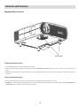
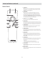
Projector Chassis Cover
To Open the Projector Cover:
1. Locate the two black cover latches under the front edge.
2. Push the latches fi rmly IN toward the center of the unit. DO NOT FORCE THE TABS. It may be easier to loosen one side fi rst, then the
other.
3. When the cover latches are loosened, then the top cover will swing upward and reveal the system control panel, cable connection panel
and more.
To Close the Projector Cover:
1. To close simply reposition the cover over the latches and press fi rmly, Latches will then snap closed.
2. IMPORTANT — When fi nished working under the cover and latches have been initially secured. Move the latches OUT TOWARD THE
COVER EDGES. This securely locks the cover to the projector.

11
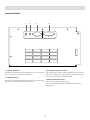
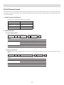
Connector Panel
RS-232C DVI
SVCSYNC
OUT
1. [SYNC OUT] Terminal
This terminal is intended for servicing purposes. Do not use it. Using
it may cause an error or malfunction of the unit.
2. [SERVICE] Terminal
This terminal is intended for servicing purposes. Do not use it. Using
it may cause an error and malfunction of the unit.
3. [RS-232C] Terminal (D-sub 9 Pin)
This is the RS-232C interface-specifi c terminal. This unit can be con-
trolled by a computer connected externally. (see page 18) • For de-
tails, please check with your authorized dealer.
4. [DVI] Terminal (DVI-D 24 Pin)
This is an input terminal for video signals.
Connect this to the VDP-80 dedicated digital video processor.
(see page 18)
12 3 4

12
Controls and Features (continued)
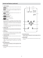
1. LAMP INDICATOR:
Light On: Indicates the lamp has been used for more than 1900
hours.
Blinking: Indicates that lamp usage time (about 2000 hours) is
exceeded. Please contact your Vidikron dealer to re-
place the lamp.
2. TEMP INDICATOR
Blinking: Indicates the temperature inside the projector is ab-
normally high.
3. POWER INDICATOR
Light On: During projection.
4. STANDBY INDICATOR
Light On: When in standby mode.
Blinking: When in cool down mode.
5. POWER BUTTON
When this projector is in standby mode, pressing this button
for more than 1 second will turn the projector on and cause the
[POWER] indicator to light up. Press it one second or more again,
and the projector goes into the cool down mode and fi nally into
stand by mode.
• The [POWER] button will not work within approximately 1 min-
ute of the light-source lamp being turned on. Hence wait about
1 minute before pressing.
6. MENU BUTTON
Press this button to enter or exit the menu mode. When the main
menu is displayed, pressing this button will cause the menu to
disappear.
7. EXIT BUTTON
Press this button to display the previous menu (For example,
from sub menu to main menu). Pressing this button when the
main menu is displayed will clear the menu.
8. CURSOR BUTTONS
These buttons are used in the menu mode to select an item, ad-
just the value etc.
9. ENTER BUTTON
Press this button to show the next hierarchical menu (for ex-
ample, to enter submenu from main menu). It is also used when
“ENTER” is displayed against a selection item on the menu
screen.
10. KEY RESET BUTTON
Use this button to reset the values to factory settings when the
“Gamma”, “White Bal.”, “Blanking” or “Picture Adjust” item in the
menu is selected.
11. MUTE BUTTON
Use this button to temporarily halt the video output. Press again
to resume
10. KEY RESET BUTTON
Use this button to reset the values to factory settings when the
“Gamma”, “White Bal.”, “Blanking” or “Picture Adjust” item in the
menu is selected.
11. MUTE BUTTON
Use this button to temporarily halt the video output. Press again
to resume.

13
*About Cool Down Mode
After projection, the heated lamp will go through a 90-second
cool-down process known as the cool down mode. This function
is to prevent damage and deformation that heat from the heated
lamp may cause to the internal components of this unit. It also pre-
vents lamp breakage and shortened lamp life.
The cool down mode is indicated by the blinking [STAND BY] in-
dicator. When in the cool down mode, the [OPERATE] button will
be disabled.
After the cool down process is completed, the unit will automati-
cally switch to the standby mode.
Note
When in the cool down mode, do not pull out the plug from the
power outlet. Also, do not block the air inlets/exhaust vents.
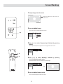
Indicator Display on the Control Panel
In addition to the standby mode, operate mode and cool down mode*, this unit also displays other operational states using diff erent
combination of indicators.
• Please refer to Page 29 for explanations on warning indication for *1 and Page 32 for *2.

14
TEST
PRESET
ENT
MUTE
LIGHT
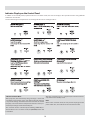
1. [ON] Button
When this unit is in the standby mode, pressing the button
for more than 1 second will turn this unit on and cause the
[OPERATE] indicator to light up.
2. [OFF] Button
When this unit is in operation (projecting), press it for 1
second or more to switch to the cool down mode, which
will automatically switch to the standby mode after about
90 seconds. The [OPERATE OFF] button will not work within
approximately 1 minute after the light source has been turned
on. Start operation only after 1 minute’s time.
3. Cursor [
3/4/5/6] Buttons
Use these buttons when adjusting the menu items.
4. [EXIT] Button
Press this button to return to the previous hierarchical menu
(for example, to return from submenu to main menu). Pressing
this button when the menu is displayed will clear the menu.
5. [MENU] Button
Press this button to display the menu. Pressing this button
when the menu is displayed clears the menu.
6. [PRESET] Button
Use this button to reset the values to factory settings when
the “Gamma”, “Color temp.”, “Mask” or “Picture shift” item in the
menu is selected.
7. [ENT] Button
Press this button to show the next hierarchical menu (for
example, to enter submenu from main menu). It is also used
when “ENTER” is displayed against a selection item on the
menu screen
8. [TEST] Button
Press this when adjusting focus, screen size or picture quality.
Press the button to switch to the test pattern image for
adjustment.
• Alter the test pattern with the [TEST] button.
• Press the [EXIT] button to return to the original image.
9. [MUTE] Button
Press this button to temporarily clear the video image. Press
again to resume.
10. [LIGHT] Button
Lights up illumination (light) of the remote control buttons for
about 10 seconds.
12
5
7
9
10
4
6
8
3
Remote Control
Controls and Features (continued)

15
Installation Environment
This unit is a precision device. Do not install it at the following
places. Doing so may cause fi re or malfunction of the unit.
• Where there is water, humidity or dust
• Where the unit may be subjected to oily or cigarette smoke
• On a soft surface such as carpet or cushion
• Where the unit may be subjected to high temperature due to
direct sunlight
• Where temperature is high or low
Allowable operation temperature range: 41–95ºF, (5–35 °C)
Allowable relative humidity range: 20% to 80% (no condensa-
tion)
Any room in which there is cigarette smoke or grease Even where
smoke and grease levels are minimal, prolonged exposure will
aff ect this unit. This unit emits heat and optical components are
cooled down by taking in large amount of air. The optical path
may be soiled by grease/dirt, thus causing images to become
dark or color projection to deteriorate. When soiling on the opti-
cal components occurs, complete removal of grease/dirt will not
be possible.
Precaution for Usage
This unit uses a light-source lamp which reaches high tem-
perature when projecting. Please do not use it in the follow-
ing ways. Doing so may cause fi re or malfunction of the unit.
• Projecting the image while the unit is on its side
• Projecting images outside the specifi ed angle
Do not use this unit by setting it beyond ±5° horizontally (left/
right) or ±25° vertically (up/down). This may cause color varia-
tion or shorten the lamp life.
• Projecting images at places where the air inlets and exhaust
vents are blocked
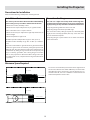
Precautions for Installation
Please read the following carefully when installing the unit.
Installing the Projector
Minimum Space Required
Do not use a cover which may enclose this unit air-tight or block
the air inlets/ exhaust vents. Allow suffi cient space around this
unit. When this unit is enclosed in a space of dimensions as in-
dicated on the left, use an air-conditioner so that internal and
external temperatures are the same.
5.9 in. / 150mm
11.8 in. / 300mm 11.8 in. / 300mm
5.9 in. / 150mm
19.68 in. / 500mm

16
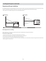
Projector and Screen Installation
The optimum image can be obtained when the center of the lens and the screen are placed perpendicular to each other. Take note of the
projection angle when placing them. Failing to do so may give rise to trapezoidal distortion of the projected image.
• This unit does not come with a function to correct trapezoidal distortion.
Side View Top View
Mounting the Unit on a Ceiling
When mounting on a ceiling, please refer to the instructions included with the ceiling mount hardware.
Precautions for Ceiling-mount
• To ceiling-mount this unit, special expertise and techniques are necessary.
Be sure to ask your dealer (or a specialist) to perform mounting (to ceilings, etc.).
• Do not mount at places that may be subjected to vibration and shock.
• Install at a safe place in case this unit or a part of it may drop. If the light-source lamp is broken, small pieces of glass from the mesh of the
fi lter may appear outside this unit
Installing the Projector (continued)

17
"#
"
#
4DSFFO
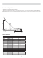
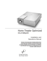
Screen Size and Projection Distance
• This unit uses a 1.3x manual zoom lens for projection.
• Although the focusable projection distance is about 4.92 ft (1.5 m) to 39.37 ft. (12 m), the projection distance recommendable for per-
formance is about 6.56 ft. (2 m) to 26.25 ft. (8 m). Install this unit within this range and adjust the screen size when the aspect ratio of the
screen is 16:9.
Simply enter the width of your screen (16X9 screen) in inches
Screen
Height
Screen
Width
min TD from SW max TD from SW
33 1/2 60 108.60 139.80
40 1/2 72 130.32 167.76
44 2/2 80 144.80 186.40
47 /2 84 152.04 195.72
48 2/2 87 157.47 202.71
50 89 161.09 207.37
50 1/2 90 162.90 209.70
51 1/2 92 166.52 214.36
53 2/2 96 173.76 223.68
56 /2 100 181.00 233.00
58 1/2 104 188.24 242.32
60 /2 107 193.67 249.31
62 1/2 111 200.91 258.63
1.81x Screen Width 2.33 x Screen Width
Throw Distance Chart

18
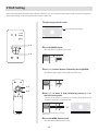
Eff ective Range of Remote Control Unit
The operable distance of the remote control unit is about 23 ft. (7 m) for direct reception. The remote control can be used by having the
transmission signal refl ected off a screen.
• If a fl uorescent lamp is lit, the remote control unit might not function properly.
When refl ecting off a screen
Ensure that total of distance A between this unit and screen and distance B between remote control and screen is within 23 ft. (7 m).
• As the eff ect of signals refl ected from the remote control unit diff er with the type of screen used, operable distance may decrease.
When directing remote control unit toward this unit
When aiming the remote control towards the remote sensor on this unit, ensure that the distance to the sensor in front or at the rear of
this unit is within 23 ft. (7 m).
• If the remote control fails to work properly, move closer to this unit
Installing the Projector (continued)

19
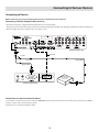
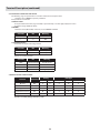
Connecting to Devices
Before connection, be sure to turn off both the projector and the device to be connected.
Connecting to the VDP-80 digital video processor
• Read the manual that is supplied with the digital video processor thoroughly.
• The signal may attenuate and the image may become unstable depending on the DVI cable. Use high quality DVI cable below 16.40 ft. (5 m).
When using DVI cable above 16.40 ft. (5 m), use LiveLink™ cable
Control from an external automation device
It is possible to control this unit by connecting the [CONTROL RS-232C] terminal of this unit for use with control systems such as AMX or
Crestron. Control codes can be found on page 36.
For details, please consult your Vidikron dealer
Short Cable
Long Cable
“Y” Cable
DVI Cable
Projector Input Panel
Controller Input Panel
Crestron/AMX
Type Automation
Control Unit
Connecting to Various Devices
Processor

20
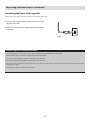
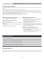
Connecting the Power Cord (supplied)
After all devices have been connected, connect the supplied power cord.
1 Connect the supplied power cord to the power input
terminal of this unit
2 Insert the main plug of the supplied power cord into the
wall outlet
(e.g.)
• Since the power requirement of this unit is high, insert the power plug directly into a wall outlet.
• When not using devices, remove the power plug from the wall outlet.
• Do not use power cords for connection other than those supplied.
• Do not use a power voltage diff erent from that which is indicated.
• Do not cut, tear or modify the power cords. Also, do not place a heavy object on, heat or stretch the power cords as this may cause
damage to the cords.
• Do not insert or pull out plugs with a wet hand.
Cautions Against Fire and Electric Shock
Connecting to Various Devices (continued)
Page is loading ...
Page is loading ...
Page is loading ...
Page is loading ...
Page is loading ...
Page is loading ...
Page is loading ...
Page is loading ...
Page is loading ...
Page is loading ...
Page is loading ...
Page is loading ...
Page is loading ...
Page is loading ...
Page is loading ...
Page is loading ...
Page is loading ...
Page is loading ...
Page is loading ...
Page is loading ...
-
 1
1
-
 2
2
-
 3
3
-
 4
4
-
 5
5
-
 6
6
-
 7
7
-
 8
8
-
 9
9
-
 10
10
-
 11
11
-
 12
12
-
 13
13
-
 14
14
-
 15
15
-
 16
16
-
 17
17
-
 18
18
-
 19
19
-
 20
20
-
 21
21
-
 22
22
-
 23
23
-
 24
24
-
 25
25
-
 26
26
-
 27
27
-
 28
28
-
 29
29
-
 30
30
-
 31
31
-
 32
32
-
 33
33
-
 34
34
-
 35
35
-
 36
36
-
 37
37
-
 38
38
-
 39
39
-
 40
40


Ask a question and I''ll find the answer in the document
Finding information in a document is now easier with AI
Related papers
-
 Vidikron Vision Model 80 User manual
-
 Vidikron Projector 60 User manual
-
 Vidikron Projector VERSION 50 User manual
-
 Vidikron Projector 90 User manual
-
 Vidikron Vision 120 User manual
-
 Vidikron Vision 10 User manual
-
 Vidikron Vision Model 140 LightAmp User manual
-
 Vidikron Vision 150 User manual
-
 Vidikron SERIES 1080p User manual
-
 Vidikron Projector 30 User manual


Other documents
-
 Faroudja DILA1080pHD User manual
-
Meridian D-ILA 1080MF2 User manual
-
Meridian Projection Television DLA-HD2KE User manual
-
-
Dukane ImagePro 9100HC User manual
-
Toshiba TACP TDP-MT500 User manual
-
Barco LX-5 User manual
-
JVC DLA-SH4KNLG User manual
-
-
Runco Projector CL-610 User manual
