Page is loading ...

DLP™ PROJECTOR
90
VERSION 1.0
OWNER’S OPERATING MANUAL


Vidikron Vision Model 90 Owner’s Operating Manual iii
TWO YEAR LIMITED WARRANTY
For Projectors, Video Processors and Controllers
Congratulations on your purchase of a Vidikron video product and welcome to the Vidikron family! With proper installation, setup
and care, you should enjoy many years of unparalleled video performance.
This is a LIMITED WARRANTY as defined in the Magnuson-Moss Warranty Act. Please read it carefully and retain it with your other
important documents.
SERVICE LABOR: Vidikron will pay for service labor by Vidikron Authorized Service Center when needed as a result of manufacturing
defect for a period of two (2) years from the effective date of delivery to the end user (excluding the lamp).
PARTS: (Not including the lamp) Vidikron will provide new or rebuilt replacement parts for the parts that fail due to defects in
materials or workmanship for a period of two (2) years from the effective date of delivery to the end user. Such replacement parts
are then subsequently warranted for the remaining portion (if any) of the original warranty period.
PROJECTOR LAMP: Vidikron will pay for service labor by a Vidikron Authorized Service Center when needed as a result of a
manufacturing defect for a period of six (6) months or 1000 hours, which ever comes first, from the effective date of delivery to the
end user. In addition, Vidikron will provide a new or rebuilt replacement lamp for the lamp that fails due to defects in materials or
workmanship for a period of six (6) months or 1000 hours, which ever comes first, from the effective date of delivery to the end
user. Such replacement lamps are then subsequently warranted for the remaining portion (if any) of the original warranty period.
This Limited Warranty only covers failure due to defects in materials and workmanship that occur during normal use and does not
cover normal maintenance. This Limited Warranty does not cover cabinets or any appearance items; failure resulting from
accident, misuse, abuse, neglect, mishandling, misapplication, faulty or improper installation or setup adjustments; improper
maintenance, alteration, improper use of any input signal; damage due to lightning or power line surges, spikes and brownouts;
damage that occurs during shipping or transit; or damage that is attributed to acts of God. In the case of remote control units,
damage resulting from leaking, old, damaged or improper batteries is also excluded from coverage under this Limited Warranty.
CAUTION: THIS LIMITED WARRANTY ONLY COVERS VIDIKRON PRODUCTS PURCHASED FROM VIDIKRON AUTHORIZED DEALERS.
ALL OTHER PRODUCTS ARE SPECIFICALLY EXCLUDED FROM COVERAGE UNDER THIS LIMITED WARRANTY. MOREOVER, DAMAGE
RESULTING DIRECTLY OR INDIRECTLY FROM IMPROPER INSTALLATION OR SETUP IS SPECIFICALLY EXCLUDED FROM COVERAGE
UNDER THIS LIMITED WARRANTY.
Vidikron limits its obligations under any implied warranties under state laws to a period not to exceed the warranty period. There
are no express warranties. Vidikron also excludes any obligation on its part for incidental or consequential damages related to the
failure of this product to function properly. Some states do not allow limitations on how long an implied warranty lasts, and some
states do not allow the exclusion or limitation of incidental or consequential damages. So the above limitations or exclusions may
not apply to you. This warranty gives you specific legal rights, and you may also have other rights that vary from state to state.
WHAT IS COVERED UNDER THE TERMS OF THIS LIMITED WARRANTY:
WHAT IS NOT COVERED UNDER THE TERMS OF THIS LIMITED WARRANTY:
RIGHTS, LIMITS AND EXCLUSIONS:

iv Vidikron Vision Model 90 Owner’s Operating Manual
This warranty begins on the effective date of delivery to the end user. For your convenience, keep the original bill of sale as
evidence of the purchase date.
Please fill out and mail your warranty registration card. It is imperative that Vidikron knows how to reach you promptly if we should
discover a safety problem or product update for which you must be notified.
Repairs made under the terms of this Limited Warranty covering your Vidikron video product will be performed at the location of
the product, during usual working hours, providing location of product is within normal operating distance from a Vidikron
Authorized Service Center. In some instances it may be necessary for the product to be returned to the Vidikron factory for repairs.
If, solely in Vidikron’s judgment, location of product to be repaired is beyond normal operating distance of the closest Vidikron
Authorized Service Center, or the repair requires the unit be returned to the Vidikron factory, it is the owner’s responsibility to
arrange for shipment of the product for repair. These arrangements must be made through the selling Vidikron Dealer. If this is not
possible, contact Vidikron directly for a Return Authorization number and shipping instructions. Vidikron will return product
transportation prepaid in the United States, unless no product defect is discovered. In that instance, shipping costs will be the
responsibility of the owner.
© Copyright 2005 Vidikron. This document contains proprietary information protected by copyright. All rights are reserved. No part
of this manual may be reproduced by any mechanical, electronic or other means, in any form, without prior written permission of
the manufacturer.
All trademarks and registered trademarks are the property of their respective owners.
EFFECTIVE WARRANTY DATE:
IMPORTANT -- WARRANTY REGISTRATION:
CONTACT A VIDIKRON AUTHORIZED SERVICE CENTER TO OBTAIN SERVICE:
COPYRIGHT AND TRADEMARKS:

Vidikron Vision Model 90 Owner’s Operating Manual v
To locate the name and address of the nearest Vidikron Authorized Service Center, or for additional information about this Limited
Warranty, please call or write:
VIDIKRON
Attn: Customer Service Department
2900 Faber Street
Union City, CA 94587
Ph: (510) 324-5900
Fax: (510) 324-5905
Toll Free: (888) 4VIDIKRON
VIDIKRON PRODUCT INFORMATION
RETAIN THIS INFORMATION FOR YOUR RECORDS
_________________________________________________________ ________________________________________
Model Purchased Date
____________________________________________________________________________________________________________
Serial Number
____________________________________________________________________________________________________________
Vidikron Authorized Dealer Name
____________________________________________________________________________________________________________
Address
____________________________________________ __________________ ________________________
City State/Province Postal Code
____________________________________________ _______________________________________________________
Phone Fax
ADDITIONAL INFORMATION:

vi Vidikron Vision Model 90 Owner’s Operating Manual
Thank you for your purchase of this quality Vidikron video projector! It has been designed to provide you with the quality of video
that is expected in a home theater. For the best performance, please read this manual carefully as it is your guide through the
menus and operation.
This equipment has been tested and found to comply with the limits for a Class B digital device, pursuant to Part 15 of the FCC
Rules. These limits are designed to provide reasonable protection against harmful interference in a residential installation.
1. Read these instructions.
2. Keep these instructions.
3. Heed all warnings.
4. Do not use this equipment near water, outdoors or otherwise exposed to the elements.
5. Clean only with a dry cloth.
6. Do not block any ventilation openings.
7. Do not install near any heat sources such as radiators, heat registers, stoves, or other apparatus (including amplifiers) that
produce heat.
8. Do not defeat the safety feature of the polarized or grounding type plug. A polarized type plug has two blades with one wider
than the other. A grounding type plug has two blades and a third grounding prong. The third prong is provided for your safety.
If the provided plug does not fit into your outlet, consult an electrician for the replacement of the obsolete outlet.
9. The 12V trigger only outputs DC 12V signal for triggering. Do not connect to any other power input or output. This could cause
damage to this unit.
10. Only use accessories specified by Vidikron International.
11. Keep the packing material in case the equipment should ever need to be shipped.
12. Unplug this projector during lightning storms or when it will not be used for an extended period of time.
13. The lamp becomes extremely hot during operation. Allow the projector to cool down for approximately 45 minutes prior to
removing the lamp assembly for replacement. Do not operate lamps beyond the rated lamp life. Excessive operation of lamps
beyond rated life could cause them to explode in rare occasions.
14. Refer all servicing to qualified service personnel. Servicing is required when the projector has been damaged in any way,
objects have fallen or spilled into the projector, the projector has been exposed to rain or moisture, does not operate normally,
or has been dropped.
Safety Precautions
WARNING
This symbol is intended to alert the user to the presence of
uninsulated “dangerous voltage” within the product’s enclosure that
may be of sufficient magnitude to constitute a risk of electric shock.
This symbol is intended to alert the user to the presence of important
operating and maintenance (servicing) instructions in the literature
accompanying the appliance.
CAUTION
RISK OF ELECTRIC SHOCK
DO NOT OPEN
CAUTION:
TO REDUCE THE RISK OF ELECTRIC SHOCK
DO NOT REMOVE COVER (OR BACK)
NO USER SERVICEABLE PARTS INSIDE.
REFER SERVICING TO QUALIFIED
SERVICE PERSONNEL.

Vidikron Vision Model 90 Owner’s Operating Manual vii
1Table of Contents
TWO YEAR LIMITED WARRANTY ..........................................................................................1-iii
Safety Precautions ................................................................................................................1-vi
1. Introduction .....................................................................................................................1-1
About This Manual ........................................................................................................................................ 1-1
Target Audience..................................................................................................................................... 1-1
If You Have Comments About This Manual... .............................................................................. 1-1
Textual and Graphic Conventions ................................................................................................... 1-1
Using This Manual ......................................................................................................................................... 1-2
Description, Features and Benefits ......................................................................................................... 1-3
Key Features and Benefits................................................................................................................... 1-3
Parts List ................................................................................................................................................... 1-4
2. Controls and Functions ...................................................................................................2-1
Vision 90 at a Glance .................................................................................................................................... 2-1
Vision 90 Rear Panel ..................................................................................................................................... 2-2
Vision 90 Remote Control ........................................................................................................................... 2-4
3. Installation .......................................................................................................................3-1
Remote Control .............................................................................................................................................. 3-1
Notes on Batteries ................................................................................................................................. 3-1
Notes on Remote Control Operation.............................................................................................. 3-1
Quick Setup ..................................................................................................................................................... 3-2
Installation Considerations ........................................................................................................................ 3-3
Installation Type..................................................................................................................................... 3-3
Screen Type and Size............................................................................................................................ 3-4
Ambient Light ......................................................................................................................................... 3-5
Other Considerations ........................................................................................................................... 3-5
Throw Distance....................................................................................................................................... 3-5
Vertical and Horizontal Position....................................................................................................... 3-6
Vertical and Horizontal Lens Shift.................................................................................................... 3-7
Adjusting the Projection Angle ........................................................................................................ 3-8
Mounting .................................................................................................................................................. 3-9
Folded Optics .......................................................................................................................................... 3-9
Connections to the Vision 90 .................................................................................................................. 3-10
Connector Panel Access ...................................................................................................................3-10

Table of Contents
viii Vidikron Vision Model 90 Owner’s Operating Manual
Connecting the Vision 90 to Source Components ..................................................................3-10
RS-232 Controller Connection ........................................................................................................3-14
Connecting 12-Volt Trigger Outputs to External Theater Components..........................3-14
Connecting to AC Power ..................................................................................................................3-14
4. Operation .........................................................................................................................4-1
Turning on the Power .................................................................................................................................. 4-1
Adjusting the Picture Orientation ........................................................................................................... 4-1
Lens Adjustments .......................................................................................................................................... 4-2
Focus ......................................................................................................................................................... 4-2
Zoom ......................................................................................................................................................... 4-2
Shift ............................................................................................................................................................ 4-2
Using the On-Screen Menus ...................................................................................................................... 4-2
Main Menu .............................................................................................................................................. 4-4
Input Source ........................................................................................................................................... 4-4
Aspect Ratio ............................................................................................................................................ 4-4
Picture ...................................................................................................................................................... 4-6
Input Position.......................................................................................................................................... 4-9
ISF Presets .............................................................................................................................................. 4-10
Information ........................................................................................................................................... 4-10
Calibration ............................................................................................................................................. 4-10
Service .....................................................................................................................................................4-12
5. Maintenance and Troubleshooting ...............................................................................5-1
Lamp Replacement ....................................................................................................................................... 5-1
Troubleshooting Tips ................................................................................................................................... 5-1
6. Serial Communications ...................................................................................................6-1
RS-232 Connection and Port Configuration ........................................................................................ 6-1
Serial Command Syntax .............................................................................................................................. 6-1
7. Specifications ...................................................................................................................7-1
Vision 90 Specifications ............................................................................................................................... 7-1
Vision 90 Dimensions ................................................................................................................................... 7-4

Vidikron Vision Model 90 Owner’s Operating Manual ix
1List of Figures
2-1. Vision 90 Front/Bottom/Side View . . . . . . . . . . . . . . . . . . . . . . . . . . . . . . . . . . . . . . . . . . . . . . . . . . . . 2-1
2-2. Vision 90 Rear Panel . . . . . . . . . . . . . . . . . . . . . . . . . . . . . . . . . . . . . . . . . . . . . . . . . . . . . . . . . . . . . . . . . . 2-2
2-3. Vision 90 Remote Control Functions . . . . . . . . . . . . . . . . . . . . . . . . . . . . . . . . . . . . . . . . . . . . . . . . . . 2-4
3-1. Flat vs. Curved Screens . . . . . . . . . . . . . . . . . . . . . . . . . . . . . . . . . . . . . . . . . . . . . . . . . . . . . . . . . . . . . . . 3-4
3-2. Estimating Throw Distance . . . . . . . . . . . . . . . . . . . . . . . . . . . . . . . . . . . . . . . . . . . . . . . . . . . . . . . . . . . 3-5
3-3. Projector Placement . . . . . . . . . . . . . . . . . . . . . . . . . . . . . . . . . . . . . . . . . . . . . . . . . . . . . . . . . . . . . . . . . . 3-6
3-4. Vertical Lens Shift . . . . . . . . . . . . . . . . . . . . . . . . . . . . . . . . . . . . . . . . . . . . . . . . . . . . . . . . . . . . . . . . . . . . 3-7
3-5. Horizontal Lens Shift . . . . . . . . . . . . . . . . . . . . . . . . . . . . . . . . . . . . . . . . . . . . . . . . . . . . . . . . . . . . . . . . . 3-7
3-6. Folded Optics . . . . . . . . . . . . . . . . . . . . . . . . . . . . . . . . . . . . . . . . . . . . . . . . . . . . . . . . . . . . . . . . . . . . . . . . 3-9
3-7. DVI Source Connections . . . . . . . . . . . . . . . . . . . . . . . . . . . . . . . . . . . . . . . . . . . . . . . . . . . . . . . . . . . . . 3-10
3-8. Digital (DTV) RGB Connections . . . . . . . . . . . . . . . . . . . . . . . . . . . . . . . . . . . . . . . . . . . . . . . . . . . . . . . 3-11
3-9. Analog RGB Connections . . . . . . . . . . . . . . . . . . . . . . . . . . . . . . . . . . . . . . . . . . . . . . . . . . . . . . . . . . . . 3-12
3-10. Composite, S-Video and Component Video Connections . . . . . . . . . . . . . . . . . . . . . . . . . . . . 3-13
3-11. RS-232 Control System Connection . . . . . . . . . . . . . . . . . . . . . . . . . . . . . . . . . . . . . . . . . . . . . . . . . 3-14
3-12. Connecting 12-Volt Trigger Outputs . . . . . . . . . . . . . . . . . . . . . . . . . . . . . . . . . . . . . . . . . . . . . . . . 3-14
4-1. Vision 90 OSD Menu Structure . . . . . . . . . . . . . . . . . . . . . . . . . . . . . . . . . . . . . . . . . . . . . . . . . . . . . . . . 4-3
4-2. Typical PLUGE Pattern for Adjusting Brightness . . . . . . . . . . . . . . . . . . . . . . . . . . . . . . . . . . . . . . . 4-6
4-3. Typical Gray Bar Pattern for Adjusting Contrast . . . . . . . . . . . . . . . . . . . . . . . . . . . . . . . . . . . . . . . . 4-7
4-4. Typical Color Bar Pattern for Adjusting Color Saturation and Tint . . . . . . . . . . . . . . . . . . . . . . . 4-8
4-5. Typical Test Pattern for Adjusting Sharpness . . . . . . . . . . . . . . . . . . . . . . . . . . . . . . . . . . . . . . . . . . 4-9
7-1. Vision 90 Dimensions . . . . . . . . . . . . . . . . . . . . . . . . . . . . . . . . . . . . . . . . . . . . . . . . . . . . . . . . . . . . . . . . . 7-4

List of Figures
x Vidikron Vision Model 90 Owner’s Operating Manual

Vidikron Vision Model 90 Owner’s Operating Manual 1-1
1.1
About This Manual
This Owner’s Manual describes how to install, set up and operate the Vidikron Vision 90 DLP
Projector. Throughout this manual, the Vidikron Vision 90 DLP Projector is referred to simply
as the “Vision 90.”
Target AudienceVidikron has prepared this manual to help home theater installers and end users get the
most out of the Vision 90.
Vidikron has made every effort to ensure that this manual is accurate as of the date it was
printed. However, because of ongoing product improvements and customer feedback, it
may require updating from time to time. You can always find the latest version of this and
other Vidikron product manuals on-line, at www.vidikron.com.
If You Have Comments About
This Manual...
Vidikron welcomes your comments about this manual. Send them to [email protected]om.
Textual and Graphic
Conventions
Text Conventions: The following conventions are used in this manual, in order to clarify the
information and instructions provided:
• Remote and built-in keypad button identifiers are set in upper-case bold type; for
example, “Press EXIT to return to the previous menu.”
• All keys with functional names are initial-capped, set in bold type and enclosed in angle
brackets. These keys are the following: <Return>, <Spacebar>, <Control>, <Esc> and
<Tab>.
• <Return> indicates that you may press either the RETURN or ENTER key on your keyboard
if it has both keys.
• Computer input (commands you type) and output (responses that appear on-screen) is
shown in monospace (fixed-width) type; for example: “To change the aspect ratio to
Letterbox, type LETTERBOX <Return>.”
In addition to these conventions, underlining, boldface and/or italics are occasionally used to
highlight important information, as in this example:
1Introduction
A carriage return must be used after each command or string.
Note

Introduction
1-2 Vidikron Vision Model 90 Owner’s Operating Manual
Graphic Conventions: These symbols appear in numerous places throughout the manual,
to emphasize points that you must keep in mind to avoid problems with your equipment or
injury:
1.2
Using This Manual
Use the following table to locate the specific information you need in this manual.
TIPS highlight time-saving short cuts and helpful guidelines for using
certain features.
NOTES emphasize text with unusual importance or special significance.
They also provide supplemental information.
CAUTIONS alert users that a given action or omitted action can degrade
performance or cause a malfunction.
WARNINGS appear when a given action or omitted action can result in
damage to the equipment, or possible non-fatal injury to the user.
DANGER appears when a given action can cause severe injury or death.
Tip
Note
Caution
WARNING
DANGER!
If you need... ... Turn to page:
Information about obtaining service iv
General information about the Vision 90 DLP
Projector
1-3
Installation instructions 3-1
First-time configuration instructions 4-1
Advanced configuration instructions 4-10
Troubleshooting tips 5-1
Vision 90 DLP Projector specifications 7-1

Introduction
Vidikron Vision Model 90 Owner’s Operating Manual 1-3
1.3
Description, Features and
Benefits
Vidikron, a world leader in the high performance home cinema market, proudly introduces
their latest high-definition digital cinema projector for the home: the Vision 90 Digital Light
Processing (DLP™) Projector.
The Vision 90 is specifically engineered to excel in the more traditionally-darkened home
theater room environment, with outstanding white field uniformity, accurate color palette,
maximum brightness and enhanced contrast performance in demand by avid home cinema
enthusiasts around the world.
The Vision 90 produces an amazing 2250 ANSI lumens of light output (CSMS™ light output of
45.3 ft-Lamberts). The Vision 90’s 16:9 native aspect ratio Digital Micromirror Device™
(DMD™) array makes it ideal for widescreen viewing, while its three-chip, 1280 x 720 native
resolution produces crisp, crystal clear high definition images with richly saturated colors,
deep black levels and natural, highly refined detail.
Unlike previous, single-chip implementations of DLP, no color wheel is used. This reduces
mechanical complexity and compromises to color spectrum purity. The Vision 90 is
enhanced further by significant horizontal and vertical lens shift capability for maximum
installation flexibility.
Vidikron’s exclusive all-digital Imagix™ video processing is integrated into the projector
chassis for the most advanced video scaling and image quality available. This advanced
design provides pure digital connections from input to light engine for absolutely stellar
pictures. In addition, Vidikron’s multiple aspect ratio control includes its unique IntelliWide™
mode for viewing standard video formats in widescreen without loss of image quality.
Discrete IR and RS-232 control make custom installation seamless, while discrete source and
aspect ratio selection accommodate any automation control system.
The Vision Model 90 is available in both a soft white or a graphite gray chassis to blend
seamlessly in your home theater environment.
Key Features and BenefitsThe Vision 90 offers these key features and benefits:
• Native Resolution: 1280 x 720 (16:9 Native Aspect Ratio)
• 3-chip Digital Light Processing (DLP™) system
• Two DVI Inputs with High-bandwidth Digital Content Protection (HDCP)
•HDTV Ready
• Multiple Lens Options for Throw Distance Flexibility

Introduction
1-4 Vidikron Vision Model 90 Owner’s Operating Manual
Parts List Your Vision 90 is shipped with the following items. If any items are missing or damaged,
please contact your Vidikron dealer or Vidikron Customer Service at (888) 4VIDIKRON.
• Vision 90 DLP Projector
•Remote Control Unit and two (2), AAA-size batteries
• AC Power Cord
• Warranty information and registration card
• Vidikron Vision Model 90 Owner’s Operating Manual (this document)
Optional Accessories:
• Ceiling mount kit
• LiveLink™ DVI Cabling System
➤

Vidikron Vision Model 90 Owner’s Operating Manual 2-1
2.1
Vision 90 at a Glance
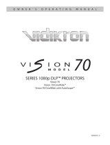
Figure 2-1 shows the key Vision 90 components.
Figure 2-1. Vision 90 Front/Bottom/Side View
1. EXHAUST VENT
2. CABLE OPENING
Pass cables through this opening.
3. LENS
4. INTAKE VENT
5. IR SENSOR
6. VIDIKRON LOGO
2Controls and Functions
65 34
122

Controls and Functions
2-2 Vidikron Vision Model 90 Owner’s Operating Manual
2.2
Vision 90 Rear Panel
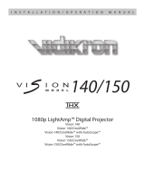
Figure 2-2 shows the Vision 90 rear panel.
Figure 2-2. Vision 90 Rear Panel
1. DVI 1 / DVI 2 (Digital)
Two, HDCP-compliant digital video inputs for connecting a DVD player or HD tuner with
a DVI or HDMI output.
2. COMPONENT VIDEO (RCA connectors)
Standard Definition (480i/576i) Component (YPrPb) input. This is the input for
component video from sources such as DVD players.
3. HD1 / HD2 (Analog BNC connectors)
Five, BNC connectors for connecting either RGB or component high-definition television
signals. The Vision 90 automatically detects the signal format: RGB(HV) or YPrPb, 480p,
720p, 480i, 576i or 1080i.
4. COMPOSITE VIDEO INPUT
Standard composite video input for connecting a VCR, laser disc player or other
composite video source.
VISION MODEL 90
DIGITAL PROJECTOR
DVI 1
DVI 1
HD1
HD2
Y
G
G
Y
HV
INPUTS
HV
HD1
HD2
INPUTS
R
Pr
Pr
R
B
Pb
Pb
B
DVI 2
DVI 2
COMPONENT VIDEO
Pb
Pr Y
COMPONENT VIDEO
Y
Pr
Pb
VIDEO
VIDEO
S-VIDEO 2
S-VIDEO 2
S-VIDEO 1
S-VIDEO 1
RS-232
CONTROL
RS-232
CONTROL
IR
IR
1
2
3
1
2
3
TRIGGERS
TRIGGERS
ENTER MENU
ENTERMENU
AC IN 110-240V 60HZ
AC IN 110-240V 60HZ
ON / OFF
OFF / ON
STANDBY / POWER
POWER / STANDBY
1237 864 5
9 10 11 151412 16 1713 1918 20
(LAMP COVER)
For best results, do not run your DVD player in progressive mode.
Tip

Controls and Functions
Vidikron Vision Model 90 Owner’s Operating Manual 2-3
5. 12-VOLT (800 mA) TRIGGER OUTPUTS
Connection for up to three (3), 12-volt trigger-controlled devices such as retractable
screens or screen masks.
6. S-VIDEO 1 / S-VIDEO 2
Two, standard S-Video inputs for connecting a DVD player, satellite receiver or Super
VHS (S-VHS) VCR.
7. IR
Wired input from an external remote control.
8. RS-232 CONTROL PORT
A female, 9-pin D-sub connector for interfacing with a PC or home theater
automation/control system.
9. VACUUM FLUORESCENT DISPLAY
Can be used instead of the On-Screen Display (OSD). Displays currently-selected menu
or -- if no menu is selected -- the current source, signal format (NTSC or PAL), input
resolution and aspect ratio.
10. UP BUTTON
Use to direct select aspect ratios or move the menu cursor up in the On-Screen Display.
When no menus are present on-screen, the UP button toggles you through aspect ratios
in the following order:
Anamorphic - Standard (4:3) - Letterbox - IntelliWide - Cinema
(For more information about aspect ratios, refer to Table 4-1.)
11. LEFT BUTTON
Used to direct select inputs or move the menu cursor left in the On Screen Display. When
no menu is present on-screen, the LEFT button toggles you through the different
sources, in this order:
DVI 2 - DVI 1 - HD/RGB2 - HD/RGB1 - Component SD - S-Video 2 - S-Video 1 - Composite
12. DOWN BUTTON
Use to direct select aspect ratios or move the menu cursor down in the On-Screen
Display. When no menu is present on-screen, this button toggles you through the
different aspect ratios, in this order:
Cinema - IntelliWide - Letterbox - Standard (4:3) - Anamorphic
13. ENTER BUTTON
When an item is highlighted on the On-Screen Display, the ENTER button selects the
item.
14. RIGHT BUTTON
Used to direct select inputs or move the menu cursor right in the On Screen Display.
When no menus are present on-screen, the RIGHT button toggles you through the
different sources, in this order:
Composite - S-Video 1 - S-Video 2 - Component SD - HD/RGB 1 - HD/RGB 2 - DVI 1 - DVI 2
15. MENU BUTTON
Pressing the MENU button will bring up the main menu. Also, if you are in an adjustment
mode or function, pressing MENU will bring the menu back one level.
16. IR SENSOR
Receives the IR commands from the remote.

Controls and Functions
2-4 Vidikron Vision Model 90 Owner’s Operating Manual
17. POWER BUTTON
Press once to turn on the Vision 90. Press it again to put it into Standby mode. For a
discrete on or off command, you can use the direct access buttons on the remote
control.
18. POWER INPUT (100 to 240 VAC)
Connect the Vision 90 to power here.
19. MAIN POWER SWITCH
Disconnects or applies power to the Vision 90.
20. POWER/STANDBY LED
2.3
Vision 90 Remote Control
Figure 2-3 shows the Vision 90 remote control, and the paragraphs that follow describe its
functionality.
Figure 2-3. Vision 90 Remote Control Functions
HD
1
HD
2
S-VID
2
S-VID
1
DVI
1
DVI
2
VIDEO
ISF
DAY
ISF
NT
CUST
1
CUST
2
MEMORY
ENT
ENT
MENU
COMP
SOURCE SELECTION
ANA 4x3
LET
BOX
I-WIDE
CINEMA
LIGHT
OFF
ON
CODE
SVC
ASPECT
12
3
45
6
7
8
1
2
7
10
14
19
22
16
11
4
3
5
6
8
12
17
18
20
21
13
9
15

Controls and Functions
Vidikron Vision Model 90 Owner’s Operating Manual 2-5
1. IR OUTPUT INDICATOR
Lights when a button is pressed to indicate that an IR signal is being transmitted.
2. LIGHT
Press to illuminate the buttons.
3. ON / OFF
Press to turn the projector on or off.
4. CODE
For Service use only.
5. Cursor Keys ( , , , )
Use these buttons to select items or settings, adjust settings or switch display patterns.
When no menus are present on-screen, the UP and DOWN buttons toggle through the
available aspect ratios, in this order:
UP Button = Anamorphic - Standard (4:3) - Letterbox - IntelliWide - Cinema
DOWN Button = Cinema - IntelliWide - Letterbox - Standard (4:3) - Anamorphic
Likewise, the LEFT and RIGHT buttons toggle through the different source inputs, in this
order:
LEFT Button = DVI 2 - DVI 1 - HD/RGB2 - HD/RGB 1 - Component SD - S-Video 2 - S-Video
1 - Composite
RIGHT Button = Composite - S-Video 1 - S-Video 2 - Component SD - HD/RGB 1 - HD/RGB
2 - DVI 1 - DVI 2
6. ENTER
Press to select a highlighted menu item or confirm a changed setting.
7. MENU
Press this button to access the OSD controls, or to exit the current menu and return to
the previous one.
Memory Preset Buttons:
8. ISF NT (Night)
Press to recall settings for the current input from the “ISF Night” memory preset.
9. ISF DAY
Press to recall settings for the current input from the “ISF Day” memory preset.
10. CUST 1
Press to recall settings for the current input from the “Custom 1” memory preset.
11. CUST 2
Press to recall settings for the current input from the “Custom 2” memory preset.

Controls and Functions
2-6 Vidikron Vision Model 90 Owner’s Operating Manual
Input Selection Buttons: Use these buttons to select an input source directly or to enter
numeric characters, as follows.
12. VIDEO (1)
Press to select Composite video input as the source.
13. S-VID 1 (2)/ S-VID 2 (5) (S-Video)
Press to select an S-Video input.
14. COMP (Component) (3)
Press to select Component SD (480i/576i) video input as the source.
15. HD 1 (4) / HD 2 (7)
Press to select a HD (RGBHV or YPbPr component) input.
16. DVI 1 (6) / DVI 2 (8)
Press to select a Digital Video input.
Aspect Ratio Selection Buttons: Use these buttons to select an aspect ratio directly or to
enter numeric characters, as follows.
17. ANA (Anamorphic) (9)
For 16:9 DVDs.
18. 4X3 (Standard 4:3) (0)
The input signal is scaled to fit 4:3 display mode in the center of the screen.
19. LETBOX (Letterbox)
Image in letterbox format is enlarged to fit 16:9 full screen display and the upper/ lower
portions are “blanked off.”
20. I-WIDE (IntelliWide)
A 4:3 image is enlarged NON-linearly in horizontal direction to fit 16:9 full screen display.
21. CINEMA
The image in the Letterbox mode is enlarged to a 16x9 image and the upper and lower portions
are compressed.
22. SVC
Reserved for future use.
/