Page is loading ...

© 3M 2018
FORM NO: 5908314 REV: A
1
AB C D
2190074
4.75 in.
(12.07 cm)
24.52 in.
(62.28 cm)
27.65 in.
(70.23 cm)
24.08 in.
(61.16 cm)
A
C
D
B
USER INSTRUCTION MANUAL
TRIPOD ROOF ANCHOR
Anchorage Connector

2
2
H
I
B
C
I
A
E
D
F
G
3 4
C
B
A
FC
B
C
FC
5 6
A. B. C. D.
E. F. G.
ABC

3
7
8 ft.
8 ft.
6 ft.
8
1 2
A
C
D
B
E
F
3
C
G
9
A B

4
10
1
A
A
B
E
2
C
E
I
3
B
G
D
C
F
4
D
C
F
5
H
C

5
11
A
B
D
C
A
9504137 Rev. L
MFRD. (YR, MO) / FABR. (AN, MO): LOT #:
MODEL NO / N° DE MODELE:
B
INSPECTION: Inspect anchor before each use. Do not use if inspection reveals an
unsafe or defective condition. Not user repairable. / Inspectez l'ancrage avant chaque
utilisation. Si une inspection révèle un état non sécuritaire ou douteux, n'utilisez pas cet
équipement. N'est pas réparable par l'utilisateur.
INSPECTION LOG
JOURNAL D'INSPECTION
INITIAL INITIAL
DATE INITIALES DATE INITIALES
SPECIFICATIONS / CARACTERISTIQUES:
Capacity / Capacité:
SRL mode: 1 person / personne,
420 lbs (191 kg)
HLL mode: 2 person / personne,
310 lbs (141 kg) max per person /
max par personne
Material / Matériau: Carbon steel and
polyester / Acier carbone et polyester
Meets / Rencontre:
OSHA 1910.140 & 1926.502
HORIZONTAL LIFELINE (HLL) MODE USE
LIGNE DE VIE HORIZONTALE (HLL) MODE
UTILISATION:
Must be used with Sayɦine Synthetic HLL. Max arresting
force 900 lbs (4 kN) per user. HLL peak force 2500 lbs
(11.1 kN). Connect tripod to a suitable anchorage on a
horizontal surface. Connect HLL to shackle. Tension HLL
system with ratchet buckle. Ratchet buckle must remain closed and locked during
use. See user manual for details. / Doit être utilisé avec le système HLL Sayɦine
Synthétique. Arrestation de max force 900 lb (4 kN) par utilisateur. Pic HLL forcer
2500 lbs (11.1 kN). Se connecter à trépied à un ancrage approprié sur une surface
horizontale. Connectez HLL à manille. Tension du système HLL avec boucle à
cliquet. Boucle à cliquet doit rester fermées et verrouillées pendant l’utilisation. Voir
le manuel de l’utilisateur pour plus de détails.
SELF-RETRACTING LIFELINE (SRL) MODE USE
LIGNE DE VIE RETRACTABLE (SRL) MODE UTILISATION:
Must be used with Smart Lock or Ultra-Lok SRL. SRL max arresting force 1800 lbs (8 kN). Connect tripod to a
suitable anchorage on a horizontal surface. Tension with ratchet buckle. Locking pin must be in place to secure
ratchet buckle onto tripod. Ratchet buckle must remain closed and locked during use. See user manual for details. / Doit
être utilisé avec Smart Lock ou Ultra-Lok SRL. Max SRL force d’arrêt 1800 lbs (8 kN). Se connecter à trépied à un ancrage
approprié sur une surface horizontale. Tension avec boucle à cliquet. Goupille de verrouillage doit être en place à boucle cliquet
sécurisé sur trépied. Boucle à cliquet doit rester fermées et verrouillées pendant l’utilisation. Voir le manuel de l’utilisateur pour plus de détails.
SWIVELING CONSTRUCTION
TRIPOD ANCHOR
ANCRE DE TRÉPIED DE CONSTRUCTION
PIVOTANT
3M.com/FallProtection
Do not remove this label.
Ne pas enlever cette étiquette.
SRL
HOOK (CONNECT TO ANCHORAGE)
CROCHET (SE CONNECTER Á ANCHORAGE)
RATCHET (LOCKED POSITION)
RATCHET (POSITION VERROUILLÉE)
LOCKING PIN
(LOCKED POSITION)
GOUPILLE DE VERROUILLAGE
(POSITION VERROUILLÉE)
SHACKLE (HLL CONNECTION)
MANILLE (CONNEXION HLL)
ÉTAPE 1: ENLEVEZ LA GOUPILLE
STEP 3: ROTATE UP
ÉTAPE 3: TOURNEZ
VERS LE HAUT
STEP 2: LIFT UP
ÉTAPE 2: SOULEVER
RATCHET (LOCKED POSITION)
RATCHET (POSITION VERROUILLÉE)
HOOK (CONNECT TO ANCHORAGE)
CROCHET (SE CONNECTER Á ANCHORAGE)
9514068 Rev. A
IN
S
PE
C
TI
O
N: Inspect anchor before each use. Do not use
i
f
i
nspect
i
on reveals an
unsafe or defect
i
ve cond
i
t
i
on. Not user repa
i
rable. / Inspectez l'ancrage avant chaque
utilisation. Si une inspection révèle un état non sécuritaire ou douteux, n'utilisez pas cet
équ
i
pement. N'est pas réparable par l'ut
i
l
i
sateur.
I
N
S
PE
C
TI
O
N L
OG
JOU
RNAL D'IN
S
PE
C
TI
O
N
INITIAL
INITIAL
DATE INITIALE
S
DATE INITIALE
S
SPECIFICATIONS / CARACTERISTIQUES:
C
apacity / Capacité
:
SRL mode: 1 person / personne,
4
20 lbs (191 kg)
H
LL mode: 2 person / personne,
3
10 lbs (141 kg) max per person /
m
ax par personn
e
M
aterial / Matériau: Carbon steel and
p
olyester / Acier carbone et polyester
M
eets / Rencontre:
OSHA 1910.140 & 1926.50
2
HORIZONTAL LIFELINE (HLL) MODE USE
LIGNE DE VIE HORIZONTALE (HLL) MODE
()
()
UTILISATION:
Must be used with Sayɦine Synthetic HLL. Max arrestin
g
f
orce 900 lbs (4 kN)
p
er user. HLL
p
eak force 2500 lbs
(
11.1 kN
)
. Connect tripod to a suitable anchorage on a
h
o
riz
o
nt
a
l
su
rf
ace
.
Co
nn
ec
t HLL t
o
s
h
ac
kl
e
. T
e
n
s
i
o
n HL
L
system with ratchet buckle. Ratchet buckle must remain closed and locked durin
g
u
se. See user manual for details. / Doit être utilisé avec le système HLL Sayɦine
S
y
nthétique. Arrestation de max force 900 lb (4 kN) par utilisateur. Pic HLL force
r
2500 lbs
(
11.1 kN
)
. Se connecter à trépied à un ancrage approprié sur une surface
horizontale. Connectez HLL à manille. Tension du système HLL avec boucle à
cli
q
uet. Boucle à cli
q
uet doit rester fermées et verrouillées
p
endant l’utilisation. Voir
le manuel de l’utilisateur pour plus de détails
.
SELF-RETRACTING LIFELINE (SRL) MODE USE
LIGNE DE VIE RETRACTABLE (SRL) MODE UTILISATION:
()
()
M
ust be used with Smart Lock or Ultra-Lok SRL. SRL max arrestin
g
force 1800 lbs
(
8 kN
)
. Connect tripod to a
su
i
table anchorage on a hor
i
zontal surface. Tens
i
on w
i
th ratchet buckle. Lock
i
ng p
i
n must be
i
n place to secure
ratchet buckle onto tr
i
pod. Ratchet buckle must rema
i
n closed and locked dur
i
ng use. See user manual for deta
i
ls. / Do
i
t
être utilisé avec Smart Lock ou Ultra-Lok SRL. Max SRL force d’arrêt 1800 lbs
(
8 kN
)
. Se connecter à trépied à un ancrage
appropr
i
é sur une surface hor
i
zontale. Tens
i
on avec boucle à cl
i
quet. Goup
i
lle de verrou
i
llage do
i
t être en place à boucle cl
i
quet
sécurisé sur trépied. Boucle à cliquet doit rester fermées et verrouillées pendant l’utilisation. Voir le manuel de l’utilisateur pour plus de détails.
S
WIVELING CONSTRUCTION
TRIPOD ANCHOR
A
NCRE DE TRÉPIED DE CONSTRUCTION
PIVOTANT
3M.com/FallProtect
i
on
Do
n
o
t r
e
m
o
v
e
th
is
l
a
b
e
l.
Ne
p
as enlever cette ét
iq
uette.
S
RL
H
OOK
(
CONNECT TO ANCHORAGE
)
CROCHET (SE CONNECTER Á ANCHORAGE)
RATCHET (LOCKED POSITION)
RATCHET (POSITION VERROUILLÉE)
L
O
CKING PIN
(
LOCKED POSITION
)
G
OU
PILLE DE VERR
OU
ILLAGE
(POSITION VERROUILLÉE)
SHACKLE
(
HLL CONNECTION
)
M
ANILLE
(
CONNEXION HLL
)
É
TAPE 1: ENLEVEZ LA GOUPILLE
S
TEP 3: R
O
TATE U
P
ÉTAPE
3:
T
OU
RNEZ
VERS LE HAUT
STEP 2
:
LIFT
U
P
ÉTAPE 2: SOULEVE
R
RATCHET
(
LOCKED POSITION
)
RATCHET (POSITION VERROUILL
É
E
)
HOOK
(
CONNECT TO ANCHORAGE
)
CROCHET (SE CONNECTER
Á
ANCHORAGE)
9
5140
6
8 Rev. A
C
D
Manufacturer's instructions supplied
Manufacturer's instructions supplied
with this product at time of shipment
with this product at time of shipment
must be followed for proper use, maintenance, and inspection. Alteration or misuse of this product, or
must be followed for proper use, maintenance, and inspection. Alteration or misuse of this product, or
failure to follow instructions, may result in serious injury or death. Make only compatible connections.
failure to follow instructions, may result in serious injury or death. Make only compatible connections.
This equipment must be installed and used under the supervision of a qualiɥed person. Fall arrest forces
This equipment must be installed and used under the supervision of a qualiɥed person. Fall arrest forces
must be limited to 1800 lbs (8 kN). Exercise caution using this equipment near hazardous thermal,
must be limited to 1800 lbs (8 kN). Exercise caution using this equipment near hazardous thermal,
electrical, or chemical sources. / On doit observer les instructions du fabriquant fournies au moment de
electrical, or chemical sources. / On doit observer les instructions du fabriquant fournies au moment de
l'expédition. Une modiɥcation ou une mauvaise utilisation de ce produit, ou le fait de négliger d'observer
l'expédition. Une modiɥcation ou une mauvaise utilisation de ce produit, ou le fait de négliger d'observer
les instructions, peut provoquer une blessure grave voire mortelle. Eɢectuer seulement des connections
les instructions, peut provoquer une blessure grave voire mortelle. Eɢectuer seulement des connections
compatibles. Cet équipement doit être installé et utilisé sous la supervision d'une personne qualiɥée.
compatibles. Cet équipement doit être installé et utilisé sous la supervision d'une personne qualiɥée.
Les forces d'arrêt des chutes doivent être limitées à 1800 lbs (8 kN). Rester prudent lors de l'utilisation
Les forces d'arrêt des chutes doivent être limitées à 1800 lbs (8 kN). Rester prudent lors de l'utilisation
de ce produit a proximité de sources thermiques, électriques ou chimiques dangereuses.
de ce produit a proximité de sources thermiques, électriques ou chimiques dangereuses.
9514258 Rev. A
9514258 Rev. A
WARNING / AVERTISSEMENT
WARNING / AVERTISSEMENT

FORM NO: 5908299 REV: A
6
SAFETY INFORMATION
Please read, understand, and follow all safety information contained in these instructions prior to the use of this Anchorage Connector.
FAILURE TO DO SO COULD RESULT IN SERIOUS INJURY OR DEATH.
These instructions must be provided to the user of this equipment. Retain these instructions for future reference.
Intended Use:
This Anchorage Connector is intended for use as part of a complete personal fall protection system.
Use in any other application including, but not limited to, material handling, recreational or sports related activities, or other activities not described in
the User Instructions, is not approved by 3M and could result in serious injury or death.
This device is only to be used by trained users in workplace applications.
! WARNING
This Anchorage Connector is part of a personal fall protection system. It is expected that all users be fully trained in the safe installation and operation
of their personal fall protection system. Misuse of this device could result in serious injury or death. For proper selection, operation, installation,
maintenance, and service, refer to these User Instructions and all manufacturer recommendations, see your supervisor, or contact 3M Technical Service.
• To reduce the risks associated with working with an Anchorage Connector which, if not avoided, could result in serious injury or
death:
- Inspect the device before each use, at least annually, and after any fall event. Inspect in accordance with the User Instructions.
- If inspection reveals an unsafe or defective condition, remove the device from service and repair or replace according to the User Instructions.
- Any device that has been subject to fall arrest or impact force must be immediately removed from service and destroyed.
- The device must only be installed in the specifi ed substrates or on structures detailed in the User Instructions. Installations and use outside the
scope of this instruction must be approved by 3M Fall Protection.
- The substrate or structure to which the anchorage connector is attached must be able to sustain the static loads specifi ed for the anchor in the
orientations permitted in the User Instructions.
- Only connect other fall protection subsystems to the designated anchorage connection point on the device.
- Prior to drilling or fastening, ensure no electric lines, gas lines, or other critical embedded systems will be contacted by the drill or the device.
- Ensure that fall protection systems/subsystems assembled from components made by different manufacturers are compatible and meet the
requirements of applicable standards, including the ANSI Z359 or other applicable fall protection codes, standards, or requirements. Always
consult a Competent or Qualifi ed Person before using these systems.
• To reduce the risks associated with working at height which, if not avoided, could result in serious injury or death:
- Ensure your health and physical condition allow you to safely withstand all of the forces associated with working at height. Consult with your
doctor if you have any questions regarding your ability to use this equipment.
- Never exceed allowable capacity of your fall protection equipment.
- Never exceed maximum free fall distance of your fall protection equipment.
- Do not use any fall protection equipment that fails pre-use or other scheduled inspections, or if you have concerns about the use or suitability
of the equipment for your application. Contact 3M Technical Services with any questions.
- Some subsystem and component combinations may interfere with the operation of this equipment. Only use compatible connections. Consult
3M prior to using this equipment in combination with components or subsystems other than those described in the User Instructions.
- Use extra precautions when working around moving machinery (e.g. top drive of oil rigs) electrical hazards, extreme temperatures, chemical
hazards, explosive or toxic gases, sharp edges, or below overhead materials that could fall onto you or your fall protection equipment.
- Use Arc Flash or Hot Works devices when working in high heat environments.
- Avoid surfaces and objects that can damage the user or equipment.
- Ensure there is adequate fall clearance when working at height.
- Never modify or alter your fall protection equipment. Only 3M or parties authorized in writing by 3M may make repairs to the equipment.
- Prior to use of fall protection equipment, ensure a rescue plan is in place which allows for prompt rescue if a fall incident occurs.
- If a fall incident occurs, immediately seek medical attention for the worker who has fallen.
- Do not use a body belt for fall arrest applications. Use only a Full Body Harness.
- Minimize swing falls by working as directly below the anchorage point as possible.
- If training with this device, a secondary fall protection system must be utilized in a manner that does not expose the trainee to an unintended
fall hazard.
- Always wear appropriate personal protective equipment when installing, using, or inspecting the device/system.
EN

7
Prior to installation and use of this equipment, record the product identifi cation information from the ID label in the
Inspection and Maintenance Log (Table 2) at the back of this manual.
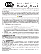
PRODUCT DESCRIPTION:
Figure 1 illustrates the 3M™ DBI-SALA™ Tripod Roof Anchor. The Tripod Roof Anchor is designed to be used as a temporarily
installed leading edge anchorage connector on concrete structures. This anchorage connector may be used as part of a personal
fall arrest system (PFAS) for use with the DBI/SALA Ultra-Lok® SRL-LE, Smart Lock SRL-LE, and DBI/SALA Sayfl ine HLL
Systems. The Tripod Roof Anchor may be used with an HLL, but may not be used as a direct anchorage and HLL anchorage
simultaneously.
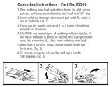
Figure 2 illustrates components of the Tripod Roof Anchor. See Table 1 for Component Specifi cations. The Tripod Roof Anchor is
comprised of a Swivel Bracket (B) mounted on a Base (C) with a Ratchet Buckle (A), Webbing (D), and Attachment Hook (E).
The Attachment Hook is inserted into an existing attach point on the roof with the Webbing routed through the Ratchet Buckle
and tightened with the Ratchet Handle until it is secure. The SRL-LE is secured in the Swivel Bracket by Locking Pins (F) inserted
through the Model Specifi c Alignment Holes (I) in the Swivel Bracket and SRL-LE Casing.
Table 1 – Specifi cations
Capacity: 1 Person with a combined weight (clothing, tools, etc.) of no more than 420 lbs (190 kg)
1
.
Anchorage: Fall Arrest: The loads applied to the Tripod Roof Anchor from personal fall arrest systems are magnifi ed
by the design of the Tripod Roof Anchor, therefore the OSHA required minimums are not appropriate. It
requires anchorages that are able to support 10,000 lbs (44.4 kN) in a vertical direction and 5,000 lbs
(22.2 kN) horizontally for fall arrest.
Restraint: The structure to which the Anchorage Connector is attached must sustain static loads applied
in the directions permitted by the Restraint System of at least 6,000 lbs (26.6 kN). When more than
one Restraint System is attached to an anchorage, the static load must be multiplied by the number of
Restraint Systems attached to the anchorage.
Roof Requirements: The Tripod Roof Anchor must be attached to a horizontal surface in an upright
position. The Attachment Hook must fully engage the anchor with the hook latch completely closed for
proper attachment. The anchor must be positioned within the tripod legs of the Base.
Multiple Anchor Installations: See Figure 7 and Section 3.1 for guidelines on installing multiple
Tripod Roof Anchors to one roof.
Dimensions: See Figure 1 for the dimensions of each Tripod Roof Anchor model.
Weight: 35 lbs (15.88 kg) without SRL
Component Specifi cations:
Figure 2
Reference Component Materials Note:
A Ratchet Buckle and Handle Steel
B Swivel Bracket Steel
C Base Steel
D Webbing Polyester Webbing
E Attachment Hook Steel
F Locking Pins Steel
G Shackle Steel
H Lynch Pin Steel
I SRL Model Specifi c Alignment Holes
1 Capacity:
This product has been tested to a 420 lbs (190 kg) Maximum Capacity per OSHA.
2 Qualifi ed Person: An individual with a recognized degree or professional certifi cate, and extensive experience in Fall Protection. This individual must be
capable of design, analysis, evaluation, and specifi cation in Fall Protection.

8
1.0 PRODUCT APPLICATION
1.1 PURPOSE: Anchorage Connectors are designed to provide anchorage connection points for Fall Arrest
1
or Fall Restraint
2
systems: Restraint, Work Positioning, Personnel Riding, Rescue, etc.
Fall Protection Only: This Anchorage Connector is for connection of Fall Protection Equipment. Do not connect
Lifting Equipment to this Anchorage Connector.
1.2 STANDARDS: Your Anchorage Connector conforms to the national or regional standard(s) identifi ed on the front cover
of these instructions. If this product is resold outside the original country of destination, the re-seller must provide these
instructions in the language of the country in which the product will be used.
1.3 SUPERVISION: Use of this equipment must be supervised by a Competent Person
3
.
1.4 TRAINING: This equipment must be installed and used by persons trained in its correct application. This manual is to
be used as part of an employee training program as required by ANSI and OSHA, and/or regional regulations. It is the
responsibility of the users and installers of this equipment to ensure they are familiar with these instructions, trained in
the correct care and use of this equipment, and are aware of the operating characteristics, application limitations, and
consequences of improper use of this equipment.
1.5 RESCUE PLAN: When using this equipment and connecting subsystem(s), the employer must have a rescue plan and
the means at hand to implement and communicate that plan to users, authorized persons
4
, and rescuers
5
. A trained, on-
site rescue team is recommended. Team members should be provided with the equipment and techniques to perform a
successful rescue. Training should be provided on a periodic basis to ensure rescuer profi ciency.
1.6 INSPECTION FREQUENCY:
The Anchorage Connector shall be inspected by the user before each use and, additionally,
by a competent person other than the user at intervals of no longer than one year.
6
Inspection procedures are described in
the “Inspection and Maintenance Log”. Results of each Competent Person inspection should be recorded on copies of the
“Inspection and Maintenance Log”.
1.7 AFTER A FALL: If the Anchorage Connector is subjected to the forces of arresting a fall, it must be removed from service
immediately, clearly marked “DO NOT USE”, and then destroyed.
2.0 SYSTEM REQUIREMENTS
2.1 ANCHORAGE: Anchorage structure requirements vary with the fall protection application. Structure on which the
Anchorage Connector is placed or mounted must meet the Anchorage Strength specifi cations defi ned in Table 1.
2.2 PERSONAL FALL ARREST SYSTEM: Figure 1 illustrates the application of this Anchorage Connector. Personal Fall Arrest
Systems (PFAS) used with the system must meet applicable Fall Protection standards, codes, and requirements. The PFAS
must incorporate a Full Body Harness and limit Arresting Force to the following values:
Maximum Arresting Force Free Fall
PFAS with Shock Absorbing Lanyard 1800 lbs (8 kN)
Refer to the instruction(s) included with your
Lanyard or SRD for Free Fall limitations.
PFAS with Self Retracting Device (SRD) 1800 lbs (8 kN)
2.3 FALL PATH AND SRD LOCKING SPEED: A clear path is required to assure positive locking of an SRD. Situations which
do not allow for an unobstructed fall path should be avoided. Working in confined or cramped spaces may not allow the
body to reach sufficient speed to cause the SRD to lock if a fall occurs. Working on slowly shifting material, such as sand
or grain, may not allow enough speed buildup to cause the SRD to lock.
2.4 HAZARDS: Use of this equipment in areas with environmental hazards may require additional precautions to prevent
injury to the user or damage to the equipment. Hazards may include, but are not limited to: heat, chemicals, corrosive
environments, high voltage power lines, explosive or toxic gases, moving machinery, sharp edges, or overhead materials
that may fall and contact the user or Personal Fall Arrest System.
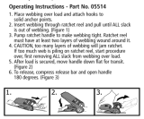
2.5 FALL CLEARANCE: Figure 3 illustrates the components of a Fall Arrest. There must be suffi cient Fall Clearance (FC)
to arrest a fall before the user strikes the ground or other obstruction. Clearance is affected by a number of factors
including: Anchorage Location, (A) Lanyard Length, (B) Lanyard Deceleration Distance or SRD Maximum Arrest Distance,
(C) Harness Stretch and D-Ring/Connector Length and Settling. Refer to the instructions included with your Fall Arrest
subsystem for specifi cs regarding Fall Clearance calculation.
1 Fall Arrest System: A collection of Fall Protection Equipment confi gured to arrest a free fall.
2 Fall Restraint System: A collection of Fall Protection Equipment confi gured to prevent the person’s center of gravity from reaching a fall hazard.
3 Competent Person: One who is capable of identifying existing and predictable hazards in the surroundings or working conditions which are unsanitary,
hazardous, or dangerous to employees, and who has authorization to take prompt corrective measures to eliminate them.
4 Authorized Person: A person assigned by the employer to perform duties at a location where the person will be exposed to a fall hazard.
5 Rescuer: Person or persons other than the rescue subject acting to perform an assisted rescue by operation of a rescue system.
6 Inspection Frequency: Extreme working conditions (harsh environments, prolonged use, etc.) may require increasing the frequency of competent person
inspections.

9
2.6 SWING FALLS: Swing Falls occur when the anchorage point is not directly above the point where a fall occurs (see Figure
4). The force of striking an object in a swing fall may cause serious injury or death. Minimize swing falls by working as directly
below the anchorage point as possible. Do not permit a swing fall if injury could occur. Swing falls will signifi cantly increase the
clearance required when a Self-Retracting Device or other variable length connecting subsystem is used.
2.7 COMPONENT COMPATIBILITY: 3M equipment is designed for use with 3M approved components and subsystems
only. Substitutions or replacements made with non-approved components or subsystems may jeopardize compatibility of
equipment and may affect the safety and reliability of the complete system.
2.8 CONNECTOR COMPATIBILITY: Connectors are considered to be compatible with connecting elements when they
have been designed to work together in such a way that their sizes and shapes do not cause their gate mechanisms to
inadvertently open regardless of how they become oriented. Contact 3M if you have any questions about compatibility.
Connectors (hooks, carabiners, and D-rings) must be capable of supporting at least 5,000 lbs. (22.2 kN). Connectors
must be compatible with the anchorage or other system components. Do not use equipment that is not compatible.
Non-compatible connectors may unintentionally disengage (see Figure 5). Connectors must be compatible in size, shape,
and strength. If the connecting element to which a snap hook or carabiner attaches is undersized or irregular in shape, a
situation could occur where the connecting element applies a force to the gate of the snap hook or carabiner (A). This force
may cause the gate to open (B), allowing the snap hook or carabiner to disengage from the connecting point (C).
Self-locking snap hooks and carabiners are required by ANSI Z359 and OSHA.
2.9 MAKING CONNECTIONS: Snap hooks and carabiners used with this equipment must be self-locking. Ensure all
connections are compatible in size, shape and strength. Do not use equipment that is not compatible. Ensure all
connectors are fully closed and locked.
3M connectors (snap hooks and carabiners) are designed to be used only as specifi ed in each product’s user’s instructions.
See Figure 6 for examples of inappropriate connections. Do not connect snap hooks and carabiners:
A. To a D-ring to which another connector is attached.
B. In a manner that would result in a load on the gate. Large throat snap hooks should not be connected to standard
size D-rings or similar objects which will result in a load on the gate if the hook or D-ring twists or rotates, unless the
snap hook complies is equipped with a 3,600 lb (16 kN) gate. Check the marking on your snap hook to verify that it
is appropriate for your application.
C. In a false engagement, where features that protrude from the snap hook or carabiner catch on the anchor, and
without visual confi rmation seems to be fully engaged to the anchor point.
D. To each other.
E. Directly to webbing or rope lanyard or tie-back (unless the manufacturer’s instructions for both the lanyard and
connector specifi cally allows such a connection).
F. To any object which is shaped or dimensioned such that the snap hook or carabiner will not close and lock, or that
roll-out could occur.
G. In a manner that does not allow the connector to align properly while under load.

10
3.0 INSTALLATION
Installation of the DBI-SALA Tripod Roof Anchor must be supervised by a Qualifi ed Person
1
. The installation must
be certifi ed by a Competent Person
2
as meeting the criteria for a Certifi ed Anchorage, or that it is capable of supporting
the potential forces that could be encountered during a fall.
1
2
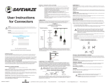
3.1 PLANNING: Plan the fall protection system prior to installation of the Tripod Roof Anchor. Account for all factors that may
affect safety before, during and after a fall. Consider all requirements, limitations and specifi cations defi ned in Section 2
and Table 1.
Anchor Placement: Figure 7 illustrates proper placement of the Tripod Roof Anchor(s) on the roof. Roof anchors must be
located and spaced properly on the roof to preserve structural strengths of the roof and roof anchor. Requirements are as
follows:
• The diameter of the anchorage cross section must be less than 1 inch (2.54 cm).
• Tripod Roof Anchors must be positioned at least 8 feet (2.44 m) from each other.
• Tripod Roof Anchors must be positioned at least 6 feet (1.83 m) from any roof edge.
• Tripod Roof Anchors are not intended to be permanently installed.
3.2 INSTALLING THE TRIPOD ROOF ANCHOR: The Tripod Roof Anchor should only be installed on horizontal, fl at roof
surfaces. Figure 8 illustrates installation of the Tripod Roof Anchor. To install the Tripod Roof Anchor:
A
Shackle
B
Lug
C
Webbing
D
Handle
E
Ratchet Lock
F
Lynch Pin
G
Ratchet Hub
1. Position the Tripod Roof Anchor directly over a suitable anchor capable of withstanding the loads given in Table 1.
2. Confi rm the Shackle attached to the Ratchet Buckle is positioned over the Lug and that the Lynch Pin is in place.
3. The latch on the Attachment Hook must fully close over the anchorage. Do not use on anchorages that load only the
tip of the hook or side load the hook. Do not use on anchorages that prevent the hook latch from closing completely.
See Figure 8.
4. Unlock the Ratchet Buckle by pulling on the Ratchet Lock and rotating the Ratchet Buckle open. Remove the slack
from the Webbing by pulling it through the Ratchet Hub.
5. Tighten the Webbing by releasing the Ratchet Lock and rotating the Ratchet Handle up and down. The ratchet
mechanism rolls the Webbing onto the Ratchet Hub.
6. Lock the Ratchet Buckle by returning the Ratchet Handle to the full down position. The Ratchet Handle must remain
in the full down position during use.
Inspection: After installation, inspect the Tripod Roof Anchor per the “Competent Person” inspection checkpoints in
the “Inspection and Maintenance Log” (Table 2).
3.3 INSTALLING THE SRL-LE: Figure 9 illustrates mounting of Smart Lock Leading Edge Self-Retracting Lifelines (A) or
Ultra-Lok Leading Edge Self-Retracting Lifelines (B) in the Tripod Roof Anchor. To install the SRL-LE in the Swivel Bracket
of the Tripod Roof Anchor:
1. Position the SRL-LE in the Swivel Bracket with the Swivel Eye on the SRL-LE aligned with the appropriate mounting
holes in the back end of the Swivel Bracket. Insert the provided Mounting Pin through the Swivel Bracket and Swivel
Eye and secure with the Cotter Pin.
2. Rotate the free end of the SRL-LE up or down until the through-hole in the SRL-LE Housing aligns with mounting
holes in the front end of the Swivel Bracket. Insert the provided Mounting Pin through the Swivel Bracket and SRL-LE
Housing and secure with the Cotter Pin.
3.4 HORIZONTAL LIFE LINE (HLL) SYSTEM: The Tripod Roof Anchor can be used as an end anchor for a 3M DBI-SALA
Sayfl ine HLL System. See instructions supplied with the HLL System for more information.
1 Qualifi ed Person:
An individual with a recognized degree or professional certifi cate, and extensive experience in Fall Protection. This individual must be capable
of design, analysis, evaluation, and specifi cation in Fall Protection.
2 Competent Person: One who is capable of identifying existing and predictable hazards in the surroundings or working conditions which are unsanitary, hazard-
ous, or dangerous to employees, and who has authorization to take prompt corrective measures to eliminate them.

11
Never connect more than one personal protective system to any single roof anchor at a time. If someone is attached to an
HLL between two tripods, no one is allowed to attach to an SRL on either of the Tripod Roof Anchors supporting that HLL.
See Figure 10 and the table below.
A Tripod Roof Anchor
B Webbing
C Ratchet
D
Shackle
E Horizontal Lifeline
F Lug
G Lynch Pin
H Keyhole
I Attachment Hook
1. Place two Tripod Anchors over anchorages capable of withstanding the loads given in Table 1 and a maximum of 60
feet (18.29 m) apart. Position each Tripod Roof Anchor so that the leg with the Ratchet Buckle faces directly toward
the other Tripod Roof Anchor.
2. Pull out as much of the Webbing as necessary to connect the Attachment Hook to the anchorage. Connect the
Attachment Hook to the anchorage. The Latch on the Attachment Hook must fully close over the anchorage. Do not
use on anchorages that load only the tip of the hook or side load the hook. Do not use on anchorages that prevent
the latch from closing completely.
3. Remove the Ratchet Buckle from the leg by fi rst removing the Lynch Pin holding the Shackle.
4. Rotate the Shackle until it clears the Lug.
5. Slide the Ratchet Buckle up the leg and pull the Ratchet Buckle out of the Keyhole.
6. Connect the HLL system to the Shackle attached to the Ratchet Buckle following the instructions supplied with the
HLL. When the HLL is secured to each of the Tripod Roof Anchors, tension the HLL by operating one or both of the
Ratchets until the line has the appropriate amount of tension as described in the HLL instructions. The Ratchet Handle
must be rotated to the full down position while the HLL is in use. Refer to Figure 10.
4.0 USE
4.1 BEFORE EACH USE: Verify that the work area and Personal Fall Arrest System (PFAS) meet all criteria defi ned in Section
2 and a formal rescue plan is in place. Inspect the Tripod Roof Anchor per the ‘User’ inspection points defi ned on the
“Inspection and Maintenance Log” (Table 2). If inspection reveals an unsafe or defective condition, do not use the system.
Remove the system from service and contact 3M regarding replacement.
4.2 FALL ARREST CONNECTIONS: The Tripod Roof Anchor is used with a full body harness and Leading Edge Self-Retracting
Lifeline (SRL-LE). Connect the SRL-LE Lifeline to the back dorsal D-ring on the harness as instructed in the instructions
included with the SRL-LE.
5.0 INSPECTION
5.1 INSPECTION FREQUENCY: The Tripod Roof Anchor must be inspected at the intervals defi ned in Section 1. Inspection
procedures are described in the “Inspection and Maintenance Log” (Table 2). Inspect all other components of the Fall
Protection System per the frequencies and procedures defi ned in the manufacturer’s instructions.
Tripod Roof Anchors are equipped with a Radio Frequency Identifi cation (RFID) Tag. The RFID Tag can be used in
conjunction with a Handheld Reading Device to simplify inspection and inventory control and provide records for your
fall protection equipment.
5.2 DEFECTS: If inspection reveals an unsafe or defective condition, remove the Tripod Roof Anchor from service immediately
and contact 3M regarding replacement. Do not attempt to repair the Fall Arrest System.
5.3 PRODUCT LIFE: The functional life of the Fall Arrest System is determined by work conditions and maintenance. As long
as the product passes inspection criteria, it may remain in service.
6.0 MAINTENANCE, SERVICING, STORAGE
6.1 CLEANING: Periodically clean the Tripod Roof Anchor metal components with a soft brush, warm water, and a mild soap
solution. Ensure parts are thoroughly rinsed with clean water.
6.2 SERVICE: If inspection reveals an unsafe or defective condition, remove the Tripod Roof Anchor from service immediately

12
and contact 3M regarding replacement. Do not attempt to repair the Fall Arrest System.
6.3 STORAGE AND TRANSPORT: When not in use, store and transport the Tripod Roof Anchor and associated fall protection
equipment in a cool, dry, clean environment out of direct sunlight. Avoid areas where chemical vapors may exist.
Thoroughly inspect components after extended storage.
7.0 LABELS
Figure 11 Illustrates labels on the Tripod Roof Anchor. Labels must be replaced if they are not fully legible.

Table 2 – Inspection and Maintenance Log
Inspection Date: Inspected By:
Components: Inspection: (See Section 1 for Inspection Frequency) User
Competent
Person
1
Tripod Roof Anchor
(Figure 2)
Inspect the Tripod Roof Anchor damage: Look for cracks, dents, or deformities. Look for
bending or wear on the Ratchet Buckle and Handle (A), Base (C), Swivel Bracket (B),
Attachment Hook (E), and Shackle (G). Inspect Webbing (D) for wear or breakage.
Inspect the entire unit for corrosion.
Confi rm the Lynch Pin (H) can be inserted through the Lug to lock the Shackle in place.
Confi rm the Locking Pins can be inserted through the holes in the Swivel Bracket and SRL-LE
and they lock into place.
Confi rm the Swivel Bracket swivels 360 degrees.
Labels (Figure 11)
Verify that all labels are securely attached and are legible (see ‘Labels’)
PFAS and Other
Equipment
Additional Personal Fall Arrest System (PFAS) equipment (harness, SRL, etc) that are used with
the Anchorage System should be installed and inspected per the manufacturer instructions.
Serial Number(s): Date Purchased:
Model Number: Date of First Use:
Corrective Action/Maintenance: Approved By:
Date:
Corrective Action/Maintenance: Approved By:
Date:
Corrective Action/Maintenance: Approved By:
Date:
Corrective Action/Maintenance: Approved By:
Date:
Corrective Action/Maintenance: Approved By:
Date:
Corrective Action/Maintenance: Approved By:
Date:
Corrective Action/Maintenance: Approved By:
Date:
Corrective Action/Maintenance: Approved By:
Date:
Corrective Action/Maintenance: Approved By:
Date:
Corrective Action/Maintenance: Approved By:
Date:
Corrective Action/Maintenance: Approved By:
Date:
Corrective Action/Maintenance: Approved By:
Date:
Corrective Action/Maintenance: Approved By:
Date:
Corrective Action/Maintenance: Approved By:
Date:
1 Competent Person: One who is capable of identifying existing and predictable hazards in the surroundings or working conditions which are unsanitary,
hazardous, or dangerous to employees, and who has authorization to take prompt corrective measures to eliminate them.


GLOBAL PRODUCT WARRANTY, LIMITED REMEDY
AND LIMITATION OF LIABILITY
WARRANTY: THE FOLLOWING IS MADE IN LIEU OF ALL WARRANTIES OR CONDITIONS, EXPRESS
OR IMPLIED, INCLUDING THE IMPLIED WARRANTIES OR CONDITIONS OF MERCHANTABILITY OR
FITNESS FOR A PARTICULAR PURPOSE.
Unless otherwise provided by local laws, 3M fall protection products are warranted against factory
defects in workmanship and materials for a period of one year from the date of installation or fi rst use
by the original owner.
LIMITED REMEDY: Upon written notice to 3M, 3M will repair or replace any product determined by
3M to have a factory defect in workmanship or materials. 3M reserves the right to require product be
returned to its facility for evaluation of warranty claims. This warranty does not cover product damage
due to wear, abuse, misuse, damage in transit, failure to maintain the product or other damage beyond
3M’s control. 3M will be the sole judge of product condition and warranty options.
This warranty applies only to the original purchaser and is the only warranty applicable to 3M’s fall
protection products. Please contact 3M’s customer service department in your region for assistance.
LIMITATION OF LIABILITY: TO THE EXTENT PERMITTED BY LOCAL LAWS, 3M IS NOT LIABLE
FOR ANY INDIRECT, INCIDENTAL, SPECIAL OR CONSEQUENTIAL DAMAGES INCLUDING, BUT NOT
LIMITED TO LOSS OF PROFITS, IN ANY WAY RELATED TO THE PRODUCTS REGARDLESS OF THE
LEGAL THEORY ASSERTED.
Garantie du produit, recours limité et limitation de responsabilité
GARANTIE : CE QUI SUIT REMPLACE TOUTES LES GARANTIES OU CONDITIONS,
EXPRESSES OU IMPLICITES, Y COMPRIS LES GARANTIES OU LES CONDITIONS
IMPLICITES RELATIVES À LA QUALITÉ MARCHANDE ET À L'ADAPTATION À UN USAGE
PARTICULIER.
L'équipement off ert par 3M est garanti contre tout défaut de fabrication en usine et de matériaux
pour une période d'un (1) an à compter de la date d'installation ou de la première utilisation par le
propriétaire initial.
RECOURS LIMITÉ : À réception d'un avis par écrit, 3M réparera ou remplacera tous les articles
défectueux à sa discrétion exclusive. 3M se réserve le droit de demander à ce que l'article défectueux
soit retourné à l'usine pour subir une inspection avant de choisir la marche à suivre appropriée. La
garantie ne couvre pas les dommages d’équipement résultant de l'usure, d’abus, les dommages subis
pendant l’expédition, le manque d'entretien du produit ou d’autres dommages en dehors du contrôle de
3M. 3M jugera seul de l'état du produit et des options de garantie. Cette garantie s’applique uniquement
à l’acheteur initial et est la seule garantie applicable à ce produit. Veuillez communiquer avec le service
à clientèle de 3M au 800-243-4630 pour obtenir de l’aide.
LIMITE DE RESPONSABILITÉ : EN AUCUN CAS 3M NE SERA TENU POUR RESPONSABLE DE
TOUT DOMMAGE INDIRECT, ACCESSOIRE, SPÉCIFIQUE OU CONSÉCUTIF INCLUANT, SANS
S'Y LIMITER, LA PERTE DE PROFIT, LIÉS DE QUELQUE MANIÈRE AUX PRODUITS, QUELLE
QUE SOIT LA THÉORIE LÉGALE INVOQUÉE.
Garantía del producto, reparaciones limitadas y limitación de obligación
GARANTÍA: LA SIGUIENTE SIRVE A MODO DE GARANTÍA O CONDICIÓN EXPLÍCITA O
IMPLÍCITA, INCLUSIVE GARANTÍAS IMPLÍCITAS O CONDICIONES DE COMERCIABILIDAD
O APTITUD PARA UN PROPÓSITO ESPECÍFICO.
El equipo que ofrece 3M tiene garantía en cuanto a defectos de fábrica en la terminación y los
materiales durante un período de un año desde la fecha de instalación o primer uso del propietario
original.
REPARACIONES LIMITADAS: Bajo aviso por escrito, 3M reparará o reemplazará todos los
elementos fallados en el momento en el que 3M lo disponga. 3M se reserva el derecho de requerir
que el elemento fallado sea devuelto a su planta para su examinación antes de determinar el accionar
apropiado a adoptar. Esta garantía no cubre los daños al equipo ocasionados por el desgaste, abuso,
daño en tránsito, mal mantenimiento u otros daños ajenos al control de 3M.. 3M será el único capaz de
determinar la condición del producto y las opciones de garantía. Esta garantía solo aplica al comprador
original y es la única válida para este producto. Para recibir asistencia, contáctese al departamento de
servicio al cliente de 3M al 800-243-4630.
LIMITACIÓN DE OBLIGACIONES: 3M NO SERÁ RESPONSABLE, BAJO NINGUNA
CIRCUNSTANCIA, DE DAÑOS INDIRECTOS, ACCIDENTALES, ESPECIALES O
CONSECUENTES, ENTRE ELLOS, PÉRDIDA DE INGRESOS, RELACIONADOS DE CUALQUIER
MANERA CON LOS PRODUCTOS, SIN CONSIDERACIÓN ALGUNA A LA TEORÍA JURÍDICA
QUE SE PUDIERA ACERTAR.

USA
3833 SALA Way
Red Wing, MN 55066-5005
Toll Free: 800.328.6146
Phone: 651.388.8282
Fax: 651.388.5065
Brazil
Rua Anne Frank, 2621
Boqueirão Curitiba PR
81650-020
Brazil
Phone: 0800-942-2300
Mexico
Calle Norte 35, 895-E
Col. Industrial Vallejo
C.P. 02300 Azcapotzalco
Mexico D.F.
Phone: (55) 57194820
Colombia
Compañía Latinoamericana de Seguridad S.A.S.
Carrera 106 #15-25 Interior 105 Manzana 15
Zona Franca - Bogotá, Colombia
Phone: 57 1 6014777
Canada
260 Export Boulevard
Mississauga, ON L5S 1Y9
Phone: 905.795.9333
Toll-Free: 800.387.7484
Fax: 888.387.7484
EMEA (Europe, Middle East, Africa)
EMEA Headquarters:
Le Broc Center
Z.I. 1re Avenue - BP15
06511 Carros Le Broc Cedex
France
Phone: + 33 04 97 10 00 10
Fax: + 33 04 93 08 79 70
Australia & New Zealand
95 Derby Street
Silverwater
Sydney NSW 2128
Australia
Phone: +(61) 2 8753 7600
Toll-Free : 1800 245 002 (AUS)
Toll-Free : 0800 212 505 (NZ)
Fax: +(61) 2 8753 7603
Asia
Singapore:
1 Yishun Avenue 7
Singapore 768923
Phone: +65-6450 8888
Fax: +65-6552 2113
Shanghai:
19/F, L’Avenue, No.99 Xian Xia Rd
Shanghai 200051, P R China
Phone: +86 21 62539050
Fax: +86 21 62539060
Korea:
3M Koread Ltd
20F, 82, Uisadang-daero,
Yeongdeungpo-gu, Seoul
Phone: +82-80-033-4114
Fax: +82-2-3771-4271
Japan:
3M Japan Ltd
6-7-29, Kitashinagawa, Shinagawa-ku, Tokyo
Phone: +81-570-011-321
Fax: +81-3-6409-5818
WEBSITE:
3M.com/FallProtection
ISO
9001
FM534873
EU DECLARATION OF CONFORMITY:
3M.com/FallProtection/DOC
GLOBAL PRODUCT WARRANTY, LIMITED REMEDY
AND LIMITATION OF LIABILITY
WARRANTY: THE FOLLOWING IS MADE IN LIEU OF ALL WARRANTIES OR CONDITIONS, EXPRESS
OR IMPLIED, INCLUDING THE IMPLIED WARRANTIES OR CONDITIONS OF MERCHANTABILITY OR
FITNESS FOR A PARTICULAR PURPOSE.
Unless otherwise provided by local laws, 3M fall protection products are warranted against factory
defects in workmanship and materials for a period of one year from the date of installation or fi rst use
by the original owner.
LIMITED REMEDY: Upon written notice to 3M, 3M will repair or replace any product determined by
3M to have a factory defect in workmanship or materials. 3M reserves the right to require product be
returned to its facility for evaluation of warranty claims. This warranty does not cover product damage
due to wear, abuse, misuse, damage in transit, failure to maintain the product or other damage beyond
3M’s control. 3M will be the sole judge of product condition and warranty options.
This warranty applies only to the original purchaser and is the only warranty applicable to 3M’s fall
protection products. Please contact 3M’s customer service department in your region for assistance.
LIMITATION OF LIABILITY: TO THE EXTENT PERMITTED BY LOCAL LAWS, 3M IS NOT LIABLE
FOR ANY INDIRECT, INCIDENTAL, SPECIAL OR CONSEQUENTIAL DAMAGES INCLUDING, BUT NOT
LIMITED TO LOSS OF PROFITS, IN ANY WAY RELATED TO THE PRODUCTS REGARDLESS OF THE
LEGAL THEORY ASSERTED.
/