68-612-01
Rev. B
07 08
Extron Electronics, USA
1230 South Lewis Street
Anaheim, CA 92805
800.633.9876 714.491.1500
FAX 714.491.1517
Extron Electronics, Europe
Beeldschermweg 6C
3821 AH Amersfoort, The Netherlands
+800.3987.6673 +31.33.453.4040
FAX +31.33.453.4050
Extron Electronics, Asia
135 Joo Seng Rd. #04-01
PM Industrial Bldg., Singapore 368363
+800.7339.8766 +65.6383.4400
FAX +65.6383.4664
Extron Electronics, Japan
Kyodo Building, 16 Ichibancho
Chiyoda-ku, Tokyo 102-0082
Japan
+81.3.3511.7655 FAX +81.3.3511.7656
www.extron.com
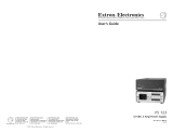
PROJECTOR
MLC 226 IP AAP
1
2 3
4
5
6
VOLUME
CONFIG
IR
PC
DVD
VCR
LAPTOP
AUTO
IMAGE
MUTE
ON
OFF
DOC
CAM
INTERCOM
MONITOR
LEVEL
HIGH
MED
LOW
IPI 104
1
2
3
4
PUSH TO TALK
ADMIN
OFFICE
LAB
SECURITY
HELP
DESK
PROJECTOR
MLC 226 IP AAP
1
2 3
4
5
6
VOLUME
CONFIG
IR
PC
DVD
VCR
LAPTOP
AUTO
IMAGE
MUTE
ON
OFF
DOC
CAM
INTERCOM
MONITOR
LEVEL
HIGH
MED
LOW
IPI 104
1
2
3
4
PUSH TO TALK
ADMIN
OFFICE
LAB
SECURITY
HELP
DESK
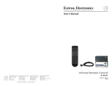
Electrostatic Discharge
Extron products with metal faceplates
designed for installation into a wall or
furniture can be adversely affected
by electrostatic discharge (ESD) if
they are not grounded
correctly.
(See the other side.)
Electrostatic Discharge
Extron products with metal faceplates
designed for installation into a wall or
furniture can be adversely affected
by electrostatic discharge (ESD) if
they are not grounded
correctly.
(See the other side.)
Grounding Extron Architectural Product Faceplates
To avoid malfunctions, if these products are not installed into a grounded
metal electrical box, ground the metal faceplates in one of two ways:
1. Ground each faceplate directly to
an earth ground. Or...
2. Tie each faceplate to its circuit
board ground via a ground pin on
one of the connectors. Refer to the
product’s manual to determine the
correct circuit ground pin.
N
Do not tie a product’s faceplate
to both a separate earth ground
and the circuit ground (via a
connector pin). If you tie a product to two
different ground sources, you may intro-
duce ground loops or other ground
ing-
related problems into the system.
N
Do not tie a faceplate to a product’s circuit
ground if the product will be installed in a
grounded metal electrical box.
N
Grounding is not required for plastic faceplates.
A B C D E
DISPLAY
RS-232/IR RS-232 12V
CM/IR/SCP
A B C D E
MLS PWR
A B
Tx/IR
Rx
GROUND
PWR SNS
GROUND
+12V OUT
Rx
Tx
GROUND
GROUND
+12V IN
+12V OUT
GROUND
CONT MOD
IR IN
SCP COM
NORMALLY OPEN
1 2
COMMON
COMMON
COMMON
GROUND
Tx/IR
Tx/IR
Tx/IR
GROUND
GROUND
A
RELAYS
IR/SERIAL OUT
3 4
B
5 6
C
A B C
Caution!
Caution!
2
1
ON
2 3 4
J1
A DB C EA DB C E
Ground each
faceplate to the
earth ground.
REAR
1
Ground
the
connector
hex nut to
the circuit
ground.
A B C D E
DISPLAY
RS-232/IR RS-232 12V
CM/IR/SCP
A B C D E
MLS PWR
A B
Tx/IR
Rx
GROUND
PWR SNS
GROUND
+12V OUT
Rx
Tx
GROUND
GROUND
+12V IN
+12V OUT
GROUND
CONT MOD
IR IN
SCP COM
NORMALLY OPEN
1 2
COMMON
COMMON
COMMON
GROUND
Tx/IR
Tx/IR
Tx/IR
GROUND
GROUND
A
RELAYS
IR/SERIAL OUT
3 4
B
5 6
C
A B C
2
1
ON
2 3 4
J1
A DB C EA DB C E
Ground each
faceplate to the
earth ground.
REAR
1
Ground
the
connector
hex nut to
the circuit
ground.
/