Page is loading ...

cadetheat.com Tel: 360-693-2505 PO Box 1675 Vancouver, WA 98668-1675
Benets You Can Depend On
SAVE THESE INSTRUCTIONS
Com-Pak Max Heater
Owner’s Guide
1”
2.54
9”
22.86
Side Grill Front Wall Can Side
12”
30.48
10”
25.4
11
1
/
8
”
28.26
3¼”
8.26
1¼”
3.18
1¾”
4.45
1¼”
3.18
3”
7.62
4”
10.16
7
7
/
8
”
20.00
Wall Can Bottom
1¾”
4.45
1¼”
3.18
3”
7.62
4”
10.16
7
7
/
8
”
20.00
10”
25.4
11
1
/
8
”
28.26
3¼”
8.26
1¼”
3.18
1”
2.54
12”
30.48
9”
22.86
Side Grill Front Wall Can Side
Wall Can Bottom
1”
2.54
9”
22.86
Side Grill Front Wall Can Side
12”
30.48
10”
25.4
11
1
/
8
”
28.26
3¼”
8.26
1¼”
3.18
1¾”
4.45
1¼”
3.18
3”
7.62
4”
10.16
7
7
/
8
”
20.00
Wall Can Bottom
1¾”
4.45
1¼”
3.18
3”
7.62
4”
10.16
7
7
/
8
”
20.00
10”
25.4
11
1
/
8
”
28.26
3¼”
8.26
1¼”
3.18
1”
2.54
12”
30.48
9”
22.86
Side Grill Front Wall Can Side
Wall Can Bottom
• Safe for you and your family
Peace of mind with automatic high temperature
shuto feature
• Our sturdiest element provides cozy warmth for
years of reliable use
• Common sense components designed with you
in mind
1. NO sharp edges
2. Corrosion resistant
3. Easy to install heater, one screw
4. Easy to install wall can
• Your Cadet heater has been thoroughly tested
and is guaranteed with a 3 year extended
warranty
(1)
Standard built-in thermostat is single pole and has no “OFF” position.
(2)
240 volt models can be used at 208 volts. Wattage equals 75% of 240v rated
wattage.
Note: Optional grill kits and wall can sold separately
TOOLS REQUIRED:
• Phillips Screwdriver
• Straight Screwdriver
• Wire Strippers
• Utility Knife
• (4) 1 ½" Wood Screws
• Insulated Wire Connectors
• (1) ½" Cable Clamp Connector
Com-Pak Max Models
Line
Voltage
Model w/o
Thermostat
Model w/
Thermostat
(1)
Watts Amps
240
(2)
CM152 CM152T
1500 6.3
800 3.3
700 2.9
CM192 CM192T
1900 7.9
1500 6.3
1100 4.6
700 2.9
400 1.7
208
CM158
1500 7.2
800 3.8
700 3.4
CM198 CM198T
1900 9.1
1500 7.2
1100 5.3
700 3.4
400 1.9
http://www.cadetheat.com/products/wall-heaters/com-pak-max
Page 1
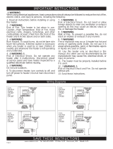
Com-Pak Max
Vertical Mount
Com-Pak Max
Horizontal Mount
Com-Pak Max Models With Thermostat
Use only with Vertical Grill and Mount Vertically or Horizontally
• Wall Thermostat Not Required
Com-Pak Max Models Without Thermostat
Use with Horizontal Grill or Vertical Grill
• Required for Use with Horizontal Grill
• Wall Thermostat Required
Rating Label
Reset Button
Built-in Thermostat

SAVE THESE INSTRUCTIONS
cadetheat.com Tel: 360-693-2505 PO Box 1675 Vancouver, WA 98668-1675
IMPORTANT INSTRUCTIONS
Wiring Diagrams
TERMOSTATO OPCIONAL
DE UN SOLO POLO
INTERRUPTOR
LIMITE DE ALTA
TEMPERATURE
DE REGLAJE
MANUAL
RESET
HIGH TEMP
LIMIT
A
C
B
HEATING ELEMENT
MOTOR
L1 L2
OPTIONAL
SINGLE POLE
THERMOSTAT
1
3
D
A
C
B
ELEMENTO CALENTADOR
MOTOR
L1 L2
1
3
D
MANUAL
RESET
HIGH TEMP
LIMIT
HEATING ELEMENT
MOTOR
L1 L2
FOR USE WITH
WALL MOUNTED
THERMOSTAT
C
B
D
TERMOSTATO OPCIONAL
DE UN SOLO POLO
INTERRUPTOR
LIMITE DE ALTA
TEMPERATURE
DE REGLAJE
MANUAL
RESET
HIGH TEMP
LIMIT
C
B
HEATING ELEMENT
MOTOR
L1 L2
OPTIONAL
SINGLE POLE
THERMOSTAT
1
3
D
A
C
B
ELEMENTO CALENTADOR
MOTOR
L1 L2
1
3
D
MANUAL
RESET
HIGH TEMP
LIMIT
HEATING ELEMENT
MOTOR
L1 L2
FOR USE WITH
WALL MOUNTED
THERMOSTAT
A
C
B
D
1. Read all instructions before installing or using
this heater.
2. This heater is hot when in use. To avoid burns,
do not let bare skin touch hot surfaces. Keep
combustible materials, such as furniture, pillows,
bedding, papers, clothes, etc. and curtains at least
3 feet (0.9 meters) from the front of the heater and
keep them away from the sides.
3. Extreme caution is necessary when any
heater is used by or near children or invalids
and whenever the heater is left operating and
unattended.
4. Do not operate any heater after it malfunctions.
Disconnect power at service panel and have
heater inspected by a reputable electrician before
reusing.
5. Do not use outdoors.
6. To disconnect heater, turn control(s) to o, and
turn o power to heater circuit at main disconnect
panel.
7. Do not insert or allow foreign objects to enter
any ventilation or exhaust opening as this may
cause an electric shock or fire, or damage the
heater.
8. To prevent a possible fire, do not block air
intakes or exhaust in any manner.
9. A heater has hot and arcing or sparking parts
inside. Do not use it in areas where gasoline,
paint, or flammable vapors or liquids are used or
stored.
10. Use this heater only as described in this
manual. Any other use not recommended by the
manufacturer may cause fire, electric shock, or
injury to persons.
11. The heater must be properly installed before
it is used.
12. Save these instructions.
WARNING
When using electrical appliances, basic precautions should always be followed to reduce the risk of fire,
electric shock, and injury to persons, including the following:
Page 2
Com-
Pak Max
Models
CM152T
and
CM158T
Com-
Pak Max
Models
CM152
and
CM158
Com-
Pak Max
Models
CM192T
and
CM198T
Com-
Pak Max
Models
CM192
and
CM198

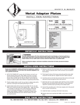
INSTALLATION INSTRUCTIONS
STRAIN RELIEF
CONNECTOR
KNOCK-OUT
(TWIST TO REMOVE)
SUPPLY WIRE
GROUNDING
SCREW
1. All electrical work and materials must com-
ply with the National Electric Code (NEC), the
Occupational Safety and Health Act (OSHA),
and all state and local codes. Canadian instal-
lations must comply with Codes Canada and
provincial codes.
2. Use copper conductors only.
3. DO NOT install the heater directly above bath-
tub or sink. DO NOT install in shower stall area.
Cadet recommends installing your heater at
least 2 feet (61 cm) away to prevent contact
with water.
4. Heater must be connected to a GFCI protected
branch circuit when installed in a bathroom.
5. Heater must be installed in a wall can:
Model CM - wall can model CC or CCSM
6. DO NOT install the heater in a floor, in the ceil-
ing, below a towel bar, behind a door, or any-
where the air discharge may be blocked in any
manner.
7. To reduce the risk of fire, do not store or use
gasoline or other flammable vapors and liquids
in the vicinity of the heater.
8. Connect grounding lead to grounding screw
provided. Keep all foreign objects out of heater.
9. Electric heaters must be installed on a circuit
dedicated to electric heaters, they cannot share
a circuit with outlets, lights, or other appliances.
__________________________
Part One
__________________________
PLACEMENT: Install the Com-Pak Max (Model CM) vertically (recommended), or horizontally with optional grill kit. Note wall can posi-
tion for correct horizontal mounting. NOT APPROVED FOR CEILING MOUNT.
THERMOSTAT: A wall thermostat is required for models without a built-in thermostat. Vertically mounted units can use built-in thermo-
stat. Horizontally mounted units must use a wall thermostat. A Cadet Electronic thermostat is recommended for ultimate control and
comfort.
REQUIRED MINIMUM distance of 6 inches from adjacent surfac-
es and 4-1/2 inches from the floor (See Figures 4a and 4b). How-
ever, Cadet RECOMMENDS 12 inches from adjacent surfaces
and floor for longer and cleaner performance. Heaters must be
spaced at least 3 feet apart.
Review the wall can label for correct direction (as noted by the UP
arrows) before mounting the wall can to the stud. In the VERTI-
CAL mounting position the element of the heater assembly will be
at the TOP. In the HORIZONTAL mounting position the element of
the heater assembly will be to the LEFT.
Keeping front of the wall can flush with the finished wall surface
(See Figure 1), secure the wall can to the stud with 2 screws (not
included) through holes provided in the wall can. The rubber shim
provided may be attached to the side of the wall can to square the
wall can to the stud (See Figure 2).
How do I install for new construction?
STEP 1
Mount The Wall Can
Figure 1
Figure 2
Face of wall
can must
extend 1/2
inch or 5/8
inch from
face of stud
to allow for
thickness of
sheetrock.
Attach wall can to stud
with screws.
STEP 2
Route Supply Wires
Route supply wire from the circuit breaker, to the thermostat, to
the wall can. For models with a built-in thermostat, route supply
wire from the circuit breaker to the wall can. Remove a knockout
from the wall can and attach the supply wire with a strain relief
connector (not included) leaving a minimum of 6 inches wire lead
for later use. Connect supply ground wire to grounding screw in
wall can (See Figure 3).
Proceed to PART TWO.
How do I install in an existing wall?
STEP 1
Cut A Hole In The Wall
REQUIRED MINIMUM distance of 6 inches from adjacent surfac-
es and 4-1/2 inches from the floor (See Figures 4a & 4b). Howev-
er, Cadet RECOMMENDS 12 inches from adjacent surfaces and
floor for longer and cleaner performance. Heaters must be spaced
at least 3 feet apart.
Vertical Mount: Cut a hole 8 inches wide by 10¼ inches high
next to a wall stud.
Horizontal Mount: Cut a hole 10¼ inches wide by 8 inches high
next to a wall stud.
STEP 2
STEP 3
Route Supply Wires
Mount The Wall Can
Review the wall can label for correct direction (as noted by the UP
arrows) before mounting the wall can to the stud. In the VERTI-
CAL mounting position the element of the heater assembly will be
at the TOP. In the HORIZONTAL mounting position the element of
the heater assembly will be to the LEFT. Insert wall can into wall
opening.
Keeping front of the wall can flush with the finished wall surface,
secure the wall can to the stud with 2 screws (not included)
through holes provided in the wall can. The rubber shim provided
may be attached to the side of the wall can to square the wall can
to the stud (See Figure 2).
(Note: Vertical installation places half round slots on the bottom,
horizontal installation places half round slots to the right).
Proceed to PART TWO.
Route supply wire from the circuit
breaker, to the thermostat, to the wall
can. For models with a built-in thermo-
stat, route supply wire from the circuit
breaker to the wall can. Remove a
knockout from the wall can and attach
the supply wire with a strain relief con-
nector (not included) leaving a minimum
of 6 inches wire lead for later use. Con-
nect supply ground wire to grounding
screw in wall can (See Figure 3).
Figure 3
Page 3

INSTALLATION INSTRUCTIONS (continued)
No change
Disconnect and cut wire with Blue Connector at
Terminal B. Cap loose end with wire connector
or wrap with electrical tape. Move Yellow
Connector from Terminal A to Terminal B.
Disconnect and cut wire with Blue Connector at
Terminal B. Cap loose end with wire connector
or wrap with electrical tape. Move Yellow
Connector from Terminal C to Terminal B.
Cut jumper wire between terminals A and C.
Cap loose ends with wire connector or wrap
with electrical tape. Remove connectors at
Terminals B and C. Move Yellow Connector
from Terminal A to Terminal B.
Cut jumper wire between terminals A and C.
Remove connectors at Terminals B and C.
Cap loose ends with wire connector or wrap
with electrical tape.
D
A
B
C
CM192/CM198
1900
1500
1100
700
400
WIRE CONFIGURATION
DESIRED WATTAGE
FACTORY SET
AT 1900 WATTS
NEVER DISCONNECT THE BLUE CONNECTOR FROM TERMINAL “D”
072512A
D
B
C
FACTORY SET
AT 1500 WATTS
NEVER DISCONNECT THE BLUE CONNECTOR FROM TERMINAL “D”
No change
Disconnect and cut wire with Blue
Connector at Terminal B. Cap loose
end with wire connector or wrap
with electrical tape.
Disconnect and cut wire with Blue
Connector at Terminal B. Cap loose
end with wire connector or wrap
with electrical tape. Move yellow
connector from Terminal C to
Terminal B
CM152/CM158
1500
800
700
WIRE CONFIGURATION
DESIRED
WATTAGE
072511A
D
B
C
FACTORY SET
AT 1500 WATTS
NEVER DISCONNECT THE BLUE CONNECTOR FROM TERMINAL “D”
No change
Disconnect and cut wire with Blue
Connector at Terminal B. Cap loose
end with wire connector or wrap
with electrical tape.
Disconnect and cut wire with Blue
Connector at Terminal B. Cap loose
end with wire connector or wrap
with electrical tape. Move yellow
connector from Terminal C to
Terminal B
CM152/CM158
1500
800
700
WIRE CONFIGURATION
DESIRED WATTAGE
072511A
No change
Disconnect and cut wire with Blue Connector at
Terminal B. Cap loose end with wire connector
or wrap with electrical tape. Move Yellow
Connector from Terminal A to Terminal B.
Disconnect and cut wire with Blue Connector at
Terminal B. Cap loose end with wire connector
or wrap with electrical tape. Move Yellow
Connector from Terminal C to Terminal B.
Cut jumper wire between terminals A and C.
Cap loose ends with wire connector or wrap
with electrical tape. Remove connectors at
Terminals B and C. Move Yellow Connector
from Terminal A to Terminal B.
Cut jumper wire between terminals A and C.
Remove connectors at Terminals B and C.
Cap loose ends with wire connector or wrap
with electrical tape.
D
A
B
C
CM192/CM198
1900
1500
1100
700
400
WIRE CONFIGURATION
DESIRED WATTAGE
FACTORY SET
AT 1900 WATTS
NEVER DISCONNECT THE BLUE CONNECTOR FROM TERMINAL “D”
072512A
R
E
S
E
T
R
E
S
E
T
GRILL
TAB
GRILL
TAB
__________________________
Part Two
__________________________
Figure 4b
Horizontal
Mounting
Figure 4a
Vertical
Mounting
After you have followed all instructions in PART ONE you are ready to install the heater assembly.
Multi-Watt Element Wiring Conguration:
STEP 1
The multi-watt heaters listed below are factory set for the highest possible wattage. If you would like to keep the wattage at the highest
setting, proceed to Step 2. If you would like to reduce your heater’s wattage from the factory setting, refer to the table below that corre-
sponds to your heater model. Once you are finished, proceed to Step 2.
STEP 1
STEP 1
How do I insert the heater assembly into the wall can?
Install Heater Assembly
STEP 2
Install Grill
STEP 3
Secure grill with the screws provided. If you have a built-in thermostat model, slide thermo stat knob onto
shaft. Turn power on at the electrical panel board.
Warranty is void if any material is sprayed on the element or blower. Use a paint mask to cover any exposed
areas of the heater if walls are to be textured or painted.
Turn heater assembly upside down (Element down with motor
facing you). Connect the supply wires to the heater wires with
connectors (See Figure 7). Now rotate the heater so the element
and the fan are facing you.
For VERTICALLY MOUNTED units the element should be at the
top. Insert the bottom edge of the heater assembly into the half
round slots (tabs) in the bottom lip of the wall can (See Figure 8a).
How do I congure my wattage?
For
MODELS
CM152
and
CM158
1500
Watt
Config-
uration
Shown
(table
above)
For
MODELS
CM192
and
CM198
1900
Watt
Config-
uration
Shown
(table
above
left)
Figure 7
Figure 8a
Figure 8b
Figure 5a
Figure 5b
Figure 6a
Figure 6b
[IMPORTANT: Push wires into bottom of wall can during insertion. Be sure that supply wires are not caught between motor and wall
can.] Attach assembly at top with screw provided.
For HORIZONTALLY MOUNTED units the element should be to the left. Insert the right edge of the heater assembly into the half round
slots (tabs) on the right side of the wall can (See Figure 8b). [IMPORTANT: Push wires into right side of wall can during insertion. Be
sure that supply wires are not caught between motor and wall can.] Attach assembly at left with screw provided.
NEVER DISCONNECT THE BLUE CONNECTOR FROM TERMINAL “D” NEVER DISCONNECT THE BLUE CONNECTOR FROM TERMINAL “D”
Page 4
Supply Wires
Heater
Wires
Top
Motor

OPERATING INSTRUCTIONS
Resetting the Manual Reset Limit Control
Warranty
How to operate your heater
The room temperature is controlled by a line voltage thermostat
located either on the wall or built-in to the heater.
1. Once installation is complete and power has been restored,
turn the thermostat knob fully clockwise.
2. When the room reaches your comfort level, turn the thermo-
stat knob counterclockwise until the heater turns o. The heater
will automatically cycle around this preset temperature.
3. To reduce the room temperature, turn the knob counterclock-
wise. To increase the room temperature, turn the knob clockwise.
About the Manual Reset Temperature Limit Control
The heater is protected by a temperature-limiting control. The
manual reset temperature limit control is designed to open the
heater circuit when excessive operating temperatures are detect-
ed. The problem must be assessed and the limit must be reset to
resume operation.
For more eective and safer operation and to prolong the life of
the heater, read the Owner’s Guide and follow the instructions.
Failure to properly maintain the heater will void any warranty and
may cause the heater to function improperly.
LIMITED THREE YEAR WARRANTY: Cadet will repair or replace
any Com-Pak Max (CM) heater found to be defective within three
years after the date of purchase.
These warranties do not apply:
1. Damage occurs to the product through improper installation or
incorrect supply voltage;
2. Damage occurs to the product through improper maintenance,
misuse, abuse, accident, or alteration;
3. The use of unauthorized accessories or unauthorized com-
ponents constitutes an alteration and voids all warranties. Refer
to Cadet website or call customer service at 855.223.3887 or
360.693.2505 for list of authorized accessories and components.
4. Cadet’s warranty is limited to repair or replacement.
5. In the event Cadet elects to replace any part of your Cadet
product, the replacement parts are subject to the same warran-
ties as the product. The installation of replacement parts does
not modify or extend the underlying warranties. Replacement
or repair of any Cadet product or part does not create any new
warranties.
If you believe your Cadet product is defective, please contact
Cadet during the warranty period, for instructions on how to have
the repair or replacement processed.
Parts and Service
Visit cadetheat.com/parts-service for information on where to
obtain parts and service.
Reduce-Reuse-Recycle
This product is made primarily of recyclable materials.
You can reduce your carbon footprint by recycling this
product at the end of its useful life. Contact your local
recycling support center for further recycling instruc-
tions.
1. Make sure all wires are properly connected
and installation is complete before you turn on
the heater.
2. Do not operate without grill.
3. Do not tamper with the high-temperature safety
shuto.
Resetting the Manual Reset Temperature Limit Control
If the manual reset limit control has opened the heater circuit due to excessive operating
temperatures, the heater will not work until the manual reset limit button is pressed.
After allowing the unit to cool for at least 10 minutes and resolving the problem causing the limit
to trip (typically the heater is blocked or needs cleaning-see Maintenance Instructions); use a
narrow object such as a ball-point pen to access the manual reset button through the upper-
left center section of the heater grill. Press FIRMLY and be sure to listen and feel for a click,
indicating it has been reset.
Complete installation
After installation, turn your heater to the highest setting and let it run for 30 minutes. Some smoking may occur as the element initially burns o residue
from manufacturing.
If your heater shows signs of overheating, such as glowing red or repeatedly getting unusually hot and shutting o, immediately turn o the circuit breaker
and call us.
If the high-temperature safety shuto trips more than once a day, replace the heater.
Page 5
Manual
Reset
Limit
Button

Troubleshooting Chart
Symptom Problem Solution
MAINTAINING YOUR HEATER
*CONSULT LOCAL ELECTRICAL CODES TO DETERMINE WHAT WORK MUST BE PERFORMED BY QUALIFIED
ELECTRICAL SERVICE PERSONNEL.
Breaker trips
immediately
upon energizing
heater.
1. Incorrect supply voltage.*
2. Overloaded circuit.*
3. A short circuit exists in the supply
or heater wiring.*
4. Defective circuit breaker.*
1. Verify that supply voltage matches the heater rating.
2. The total amperage of all heaters on a branch circuit must not be more than
80% of the amperage rating of the circuit breaker and supply wire ratings. Use a
lower wattage heater, or reduce the number of heaters on the circuit.
3. Shorted supply or heater wires may be accompanied by severe sparking.
Inspect all supply and heater wiring insulation for damage. Do not reset the circuit
breaker until all electrical shorts have been repaired.
4. Replace the circuit breaker.
Heater fan op-
erates, but does
not discharge
warm air.
1. Insucient element temperature.
2. Incorrect supply voltage.*
3. Element has failed.*
1. Allow a few moments for element to reach operating temperature.
2. Verify that supply voltage matches the heater rating.
3. Replace element.
Heater will not
shut o.
1. Heat loss from room is greater than
heater capacity.*
2. Defective thermostat.
3. Thermostat wired incorrectly to
heater.*
1. Close doors and windows. Provide additional insulation, or install a higher
wattage heater or multiple heaters if necessary. (If your circuit is rated for more
capacity.)
2. Adjust thermostat to its lowest setting. If heater continues to run (allow two
minutes for the thermostat to respond), and room temperature is greater than 50˚;
replace the thermostat.
3. Refer to thermostat documentation and correct wiring.
Heater dis-
charges smoke
or emits a burnt
odor.
1. Dust, lint or other matter has
accumulated inside heater.
2. Poor or loose electrical connec-
tions.
1. Clean heater (see “Maintenance” section above for instructions).
2. Turn o power at circuit breaker. Inspect all supply and heater wire connections
to make sure nothing is loose or poorly connected. Secure or reconnect all loose
connections. Do not reset circuit breaker until all connections have been checked
and repaired.
Element heats
for a moment
without the fan
turning, then im-
mediately stops
heating.
1. Defective motor or internal
connection.*
2. Fan or motor jammed.
1. Heater or fan motor requires replacement.
2. Remove obstruction and press heater manual reset button (see “Operating”
section for instructions).
Heater does not
run.
1. Thermostat set too low.
2. Heater has tripped the manual
reset temperature limit control.
3. Grill pressed against manual reset
button, tripping the manual reset
temperature limit control.
4. Power not on at the circuit breaker.
5. Broken or poorly connected wire(s)
to heater.
6. Defective thermostat.
1. Adjust thermostat to a higher temperature until heater operates (see Problem #6
if the problem persists).
2. Press the manual reset button (see “Operating” section for instructions).
3. Position grill so louvers do not press against manual reset button.
4. Turn on the correct circuit breaker in the main panel.
5. Turn o power at circuit breaker. Check supply wire continuity and proper con-
nection to heater wires.
6. The entire heater, or any of its components may be checked for continuity to
determine the cause of any problems. Repair or replace the heater or thermostat.
Heater contin-
ually trips the
manual reset
temperature
limit control.
1. Dust, lint or other matter has accu-
mulated inside heater.
2. Airflow is blocked.
3. Fan or motor is jammed.
4. None of the above.
1. Clean heater (see “Maintenance” section for instructions).
2. Remove obstruction. Maintain a minimum distance of 6 inches from adjacent
surfaces, 4.5 inches from the floor, and 3 feet from furniture or other objects
placed directly in front of the heater.
3. Remove obstruction, and press heater manual reset button (see “Operating”
section for instructions).
4. Replace heater assembly.
Clean heater at least every 6 months or as required. Do not lubricate motor. WARNING – Risk of electrical shock,
turn o power before removing grill.
1. Turn o power at the main disconnect panel.
2. Wait for the heater to cool.
3. Remove knob (if any) and grill.
4. Wash grill with hot soapy water and dry.
5. Blow air through the heating element with a hair dryer or shop vacuum
on blow cycle.
6. Clean the fan with a vacuum cleaner.
7. Replace grill and knob (if any).
8. Turn power back on at the main disconnect panel.
Any service other than cleaning should be performed by an authorized service representative.
©2018 Cadet Printed in USA Rev 06/01/18 #730082
Page 6
/