Page is loading ...

A: 9300 S.W. Gemini Drive Beaverton, OR 97008 USA W: www.biamp.com
APR 2020
585.0200
ESD Safety Instructions
ATTENTION: Read “Requirements for ESD Safe Work Stations”
before proceeding to card replacement instructions.
Requirements for ESD Safe Work Stations
Biamp Systems requires any eld service of Tesira products to be
performed on ESD-safe (Electrostatic Discharge) workstations. This will
minimize the chances of damaging the sensitive circuitry contained in
Biamp products. Damage is typically not noticeable to a user and may
not occur immediately. See Figure 1 for one example of a factory ESD-
safe work station.
Other options for an ESD-safe work station is using a conductive mat,
conductive wrist-strap and grounding cords as shown in Figure 2.
• The wrist strap is electrically connected to mat and chassis of the
unit under test
• The grounding cord connects to a common connection with the
wrist strap ground which is connected to a ground point (electrical
outlet)
Grounding will drain most of the static charge o to ensure the voltage
potentials of the technician and equipment remain equal.
When working outside a shop environment (in the “eld”) a fully protected,
ESD-safe workstation may not be practical. In this situation it is critical to
ensure the technician and equipment under test are at the same voltage
potential. This applies to ESD-sensitive parts that may be removed.
Damage from ESD occurs from the rapid discharge of electricity through
circuitry or components. Taking proper ESD precautions makes sure no
discharge can occur, as the voltage between the user and the unit is the
same.
Figure 3 shows the minimum ESD precautions (ESD wrist strap
connected to the unit under test).
Figure 1 Factory ESD-Safe Work Station
Figure 2 Wrist Strap and Grounding Cords
Figure 3 Minimum Conguration Workstation

page 2 Installation and Operation Guide Tesira Card Kit
ESD Safety Instructions
An ESD-safe work mat may be rolled out and trimmed to t a clean,
solid work surface. Mat surface should be cleaned weekly with a mild
detergent and water or a static-control cleaning solution. Solvents should
not be used to clean ESD-safe surfaces as they can compromise the
conductive nature of the work surface. Food should never be consumed
at an ESD-safe workstation.
Figure 4 shows an example of an ESD-safe work surface that includes
a wrist strap with a grounding cord and a grounding cord that snaps
into the ESD mat. The ESD mat grounding cord connects to a common
connection with the wrist strap ground which is then connected to a
ground point (electrical outlet).
Wrist straps should be adjusted for a comfortable, snug t. They must
be in contact with bare skin and never worn over a cu or sleeve. The
ground cord snaps directly to the buckle on the wrist strap.
Other ESD workstation options include heel-strap grounders as well as
oor mats that may also be connected to a common grounding point.
It is the responsibility of the technician to make sure work performed is
done so in an ESD-safe environment. ESD products described herein
are available from numerous manufacturers/distributors.
Ordering Tesira Server Cards
Tesira SERVER and SERVER I/Os that are ordered with factory-installed
I/O cards have these cards placed within the device in a specic order.
If modifying I/O cards in these devices, it is important to know the proper
order in which the cards are installed.
Server Card Order
Tesira SERVER-I/O has 14 card slots while the Tesira SERVER has
three. Certain slots have restrictions as to the type of cards that can be
installed.
• The last slot in either device (slot 14 in the SERVER I/O; slot 3 in
the SERVER) must always have a network card installed (SNC-1
or SNC-2, depending on the type of server.) This card is factory-
installed and does not need to be ordered separately.
• SERVER: slot 2 must have an AVB-1 card installed; slot 1 can
support an additional AVB-1 card.
• SERVER-IO: only slots 11-13 can support audio networking cards
(SCM-1 and DAN-1,) and slot 13 is the only slot that can support
an AVB-1 card.
• A SERVER-IO can support the following in any combination:
» Maximum of one AVB-1 card
» Maximum of two SCM-1 cards
» Maximum of two DAN-1 cards
» Maximum of six telephony cards (STC-2, SVC-2)
• SERVER and SERVER-IO both ship with one DSP-2 card
installed.
» Two additional DSP-2 cards may be installed in the SERVER-
IO
» Seven additional DSP-2 cards may be installed in the
SERVER
Figure 4 ESD-Safe Work Surface

Tesira Card Kit Installation and Operation Guide page 3
Server Identication
New SERVER and SERVER IO chassis may be identied by the following
features:
• One mounting hole to secure the cards through the main board
to the chassis
• Single mounting point on the board of the chassis for cards (some
chassis may have tape over the front row card holes on the main
board while newer versions will not have these holes)
Each I/O card is either an input card, output card, telephony card or an
audio networking card. The card type will aect the slot in which it is
located.
When viewing the Tesira server from the rear panel:
• Input cards are populated from the right-hand side
• Audio networking cards are populated from the left-hand side
• Telephony cards are populated from the left, after any audio
networking cards
• Output cards are populated from the left, after any audio
networking or telephony cards
• Any blank/empty slots will be in the middle between the input and
output cards (assuming both are installed)
• A maximum of twelve input/output cards may be installed (SIC-4,
SEC-4, SAC-4 SOC-4)
Tesira Server Cards
Figure 5 shows a Tesira SERVER-IO with cards installed in the slots as
noted:
Figure 5 Tesira SERVER IO Card Order
Figure 4 ESD-Safe Work Surface

page 4 Installation and Operation Guide Tesira Card Kit
Old SERVER and SERVER IO chassis may be identied by the following
features:
• Three screws secure each card plate to the rear of the chassis
• Two mounting holes to secure cards through the main board to
the chassis
Server Identication
New SERVER and SERVER IO chassis may be identied by the following
features:
• A single hole on the face plate of the card to secure it to the rear
of the chassis
• A single mounting bracket on the body of the card to screw
through the main board to the chassis
Old SERVER and SERVER IO chassis may be identied by the following
features:
• Three holes on the plate of the card to secure it to the rear of the
chassis
• Two mounting brackets for screws through the main board to the
chassis
Figure 8 “New” Server Identication
Figure 7 Server Identication
Figure 9 “Old” Server Identication

Tesira Card Kit Installation and Operation Guide page 5
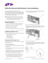
Removing & Installing I/O Cards in Tesira Servers
NOTE: Refer to Requirements for ESD Safe Work Stations before
proceeding.
1. Before removing power from the Tesira server, do the steps that
follow:
a. Save a backup copy of the conguration le loaded in the
Tesira server (if applicable)
i. Connect to the Tesira system with Tesira software.
ii. Disconnect from the system and choose File → Save As.
b. “Reset Device” on the Tesira server to clear out the
conguration le. This is done from the Device Maintenance
window in Tesira software (System→ Network→ Perform
Device Maintenance).
c. Update rmware to the latest version on the Tesira server to
avoid mismatches when adding new I/O cards to an older
device. See http://support.biamp.com for rmware upgrade
instructions.
CAUTION: FAILURE TO FOLLOW ESD REQUIREMENTS CAN
RESULT IN DAMAGE TO EQUIPMENT.
NOTE: Procedures are similar for new and older chassis, except
where specied.
2. Remove the top cover:
a. Disconnect all cables (including the power cable) and
connectors from the Tesira server.
b. Move the device to an ESD-work area with a grounded, anti-
static mat.
c. Properly ground yourself using an ESD wrist strap.
d. For new chassis:
i. Remove the six screws along the top of the front and rear
panels
ii. Pull up on the tabs protruding from the rear of the top
cover to dislodge it.
iii. Pull the top up to remove it from the chassis.
e. For an old chassis:
i. Remove the three screws along the top of the front and
rear panels
ii. Pull up on the tabs protruding from the rear of the top
cover to dislodge it.
iii. Pull the top cover towards the rear of the device to
remove it. Manipulate (wiggle) the top cover as required
to dislodge the stepped tabs out of their slots.
3. To remove and replace an I/O card, do the steps that follow:
a. For new chassis, remove the screw that secures the I/O card
to the rear chassis (located at the top-right of the card face
plate).
b. For older chassis, remove the three screws that attach the
card to the rear of the chassis.
c. Remove the screw that secures the I/O card to the main
board.
NOTE: DSP-2 cards (internal to the unit) are secured with two
screws. Grasp the front and back of the I/O card and carefully lift
upward to unseat it from the chassis.
d. Place the removed card in an ESD-safe/ant-static bag. Use
the bag a new card was packaged in after removal, if desired.
e. See previous section on card order and insert the new card
into the appropriate slot.
i. Apply gentle downward pressure until the card fully seats.
f. Secure the I/O card onto the main board using the previously-
removed screws.
NOTE: Older cards have a front and rear mounting bracket; new
cards have only one bracket. If installing old cards on a new
chassis, or a new card in an older chassis, only install the screw at
the rear of the main board.
g. Secure the I/O card to the rear of the chassis using the
previously-removed screws (top-right of the card face plate).

page 6 Installation and Operation Guide Tesira Card Kit
NOTE: Older cards installed in a new chassis will only need to
be secured at the top right hole. The same applies to new cards
installed in an older chassis.
4. To install an additional card, do the steps that follow:
a. See previous section on card order to make sure cards are
installed correctly.
b. Remove the screw from the main board where the new card
will be installed.
c. If installing a DSP-2 card (internal to the unit,) remove both
screws from the slot.
d. For older chassis, remove two screws that secure the cards
to the main board.
e. If a “short” card is being added to an older server, only the
screw at the rear of the unit needs to be removed and reused.
f. Remove the screw(s) that secure the metal plate covering
the hole the new card will occupy and remove the plate (older
chassis will have three screws securing the plate.) The metal
plate may be discarded.
g. See previous section on card order and insert the new card
into the appropriate slot.
h. Apply gentle downward pressure until the card fully seats.
i. Secure the I/O card onto the main board using the previously-
removed screws.
NOTE: Older cards have a front and rear mounting bracket; new
cards have only one bracket. If installing old cards on a new
chassis, or a new card in an older chassis, only install the screw
at the rear of the main board. Older chassis mount cards internally
with one or two screws through the main board depending on the
length of the board.
j. Secure the I/O card to the rear of the chassis using the
previously-removed screws (top-right of the card face plate.)
NOTE: Older cards installed in a new chassis will only need to
be secured at the top right hole. The same applies to new cards
installed in an older chassis.
5. For a new chassis, install the top cover as follows:
a. Place the top cover on the chassis and line up the tabs. Push
down to secure the cover.
b. Install the six screws that secure the cover to the chassis.
6. For an old chassis, install the top cover as follows:
a. Line up the top cover tabs with slots at the front of the chassis.
b. Push down on the rear of the top cover to secure it to the
chassis.
c. Install the three screws that secure the rear panel to the top
cover.
i. Make sure the rear cover tabs slide into the rear panel.
This may require manipulation of the rear panel (slightly
prying it away from the top cover).
7. To modify and reload the conguration le, do the steps that
follow:
a. Reattach all previously removed cable connections and apply
power to the Tesira server.
b. Start the Tesira software and open the conguration (.tmf) le
from the software.
i. Go to System→Equipment Table and locate the serial
number of the device that was modied.
ii. Click the serial number to open the drop-down menu and
select “None.”
iii. Click OK to close the Equipment Table window.
a. Modify the conguration le based on the I/O cards that have
been added or removed from the system.
b. From System→Equipment Table click the serial number
column of the device that was modied.
i. Make sure the drop-down menu includes the serial
number of the device.
ii. Select the serial number to assign it to the device in the
Equipment Table.
iii. Click OK to close the Equipment Table window.
c. Go to System→Network→Send Conguration to send the
modied le to the Tesira server.

Tesira Card Kit Installation and Operation Guide page 7
EX-MOD Card Order
EX-MOD, the Tesira modular AVB expander, has three card slots that
accept expander input and output cards (listed below). If an EX-MOD
contains dierent types of cards, they will always be installed in the
following order from the lowest slot number to the highest:
Removing and Installing I/O Cards in Tesira EX-MOD
NOTE: Refer to Requirements for ESD Safe Work Stations before
proceeding.
8. Before removing power from the Tesira server, do the steps that
follow:
a. Save a backup copy of the conguration le loaded in the
Tesira device (if applicable)
i. Connect to the Tesira system with Tesira software.
ii. Disconnect from the system and choose File → Save As.
b. “Reset Device” on the Tesira device to clear out the
conguration le. This is done from the Device Maintenance
window in Tesira software (System→ Network→ Perform
Device Maintenance).
c. Update rmware to the latest version on the Tesira device
to avoid mismatches when adding new I/O cards to an older
device. See http://support.biamp.com for rmware upgrade
instructions.
CAUTION: FAILURE TO FOLLOW ESD REQUIREMENTS CAN
RESULT IN DAMAGE TO EQUIPMENT.
9. Remove the top cover:
a. Disconnect all cables (including the power cable) and
connectors from the Tesira server.
b. Move the device to an ESD-work area with a grounded, anti-
static mat.
c. Properly ground yourself using an ESD wrist strap.
d. Remove the three back screws, two side screws and three
front screws that secure the cover to the chassis.
10. To remove and replace an I/O card, do the steps that follow:
a. Remove the two screws at each corner of the card that secure
it to the main board.
b. Carefully lift up and push the card away from the chassis.
c. Place the removed card in an ESD-safe/ant-static bag. Use
the bag a new card was packaged in after removal, if desired.
d. See previous section on card order and insert the new card
into the appropriate slot.
e. Apply gentle downward pressure until the card fully seats.
f. Secure the I/O card onto the main board using the previously-
removed screws.
11. Install the top cover:
a. Put the cover in place on the chassis and align the screw
holes.
b. Install the three back screws, two side screws and three front
screws that secure the cover to the chassis.
Figure 10 EX_MOD Card Order Example
A. EIC-4
B. EIOC-4
C. EOC-4
D. EOC-4

page 8 Installation and Operation Guide Tesira Card Kit
Amplier Card Order
The Tesira Ampliers have three card slots that accept expander input
and output cards (listed below). If an amplier contains dierent types of
cards, they will always be installed in the following order from the lowest
slot number to the highest:
Removing & Installing I/O Cards in Tesira Ampliers
NOTE: Refer to Requirements for ESD Safe Work Stations before
proceeding.
12. Before removing power from the Tesira server, do the steps that
follow:
a. Save a backup copy of the conguration le loaded in the
Tesira device (if applicable)
i. Connect to the Tesira system with Tesira software.
ii. Disconnect from the system and choose File → Save As.
b. “Reset Device” on the Tesira device to clear out the
conguration le. This is done from the Device Maintenance
window in Tesira software (System→ Network→ Perform
Device Maintenance).
c. Update rmware to the latest version on the Tesira server to
avoid mismatches when adding new I/O cards to an older
device. See http://support.biamp.com for rmware upgrade
instructions.
CAUTION: FAILURE TO FOLLOW ESD REQUIREMENTS CAN
RESULT IN DAMAGE TO EQUIPMENT.
13. Remove the top cover:
a. Disconnect all cables (including the power cable) and
connectors from the Tesira amplier.
b. Move the device to an ESD-work area with a grounded, anti-
static mat.
c. Properly ground yourself using an ESD wrist strap.
d. Remove the six screws that secure the cover to the chassis.
14. To remove and replace an I/O card, do the steps that follow:
a. Remove the two screws at each corner of the card that secure
it to the main board.
b. Carefully lift up and push the card away from the chassis.
c. Place the removed card in an ESD-safe/ant-static bag. Use
the bag a new card was packaged in after removal, if desired.
d. See previous section on card order and insert the new card
into the appropriate slot.
i. Apply gentle downward pressure until the card fully seats.
e. Secure the I/O card onto the main board using the previously-
removed screws.
15. Install the top cover:
a. Put the cover in place on the chassis and align the screw
holes.
b. Install the six screws that secure the cover to the chassis.
Figure 11 Amplier Card Order
A. EIC-4
B. EIOC-4
C. EOC-4

A: 9300 S.W. Gemini Drive Beaverton, OR 97008 USA W: www.biamp.com
APR 2020
585.0200
CONTACT US
Email
support@bimap.com
Web
support.bimap.com
Safety and Compliance
www.biamp.com/compliance
https://www.biamp.com/legal/warranty-information
Warranty
Please contact support for factory service or visit the website to locate your
nearest Authorized Field Service Station. You must obtain a Return Authorization
(R/A) number prior to the return of your product for factory service.
/