American Standard TU186500.002 Installation guide

Category
Sanitary ware
Type
Installation guide
- 1 -
Product names listed herein are trademarks of AS America, Inc.
© AS America, Inc. 2018
Thank you for selecting American Standard...
the benchmark of fine quality for over 140 years.
RECOMMENDED TOOLS
M965938 (8/18)
ROUGHING-IN DIMENSIONS
Fluent
®
Pressure Balancing Bath
and Shower Trim Kit
INSTALLATION
INSTRUCTIONS
TU186500
TU186501
TU186501XH
TU186502
TU186507
TU186508
Plumbers’ Putty
or Caulking
Adjustable Wrench Channel Locks
Phillips Screwdriver
To assure proper positioning in relation to wall.
Note roughing-in dimensions.
Teon Tape Flat Blade Screwdriver
CARTRIDGE INSTALLATION
11
1
2
6
5
3
4
UP
UP
O f f
C
H
FINISHED
WALL
TOP OF TUB RIM
BOTTOM OF TUB
3-3/4" REF.
(95 mm)
1/2" COPPER
7-1/2" REF.
(191 mm)
4" (102 mm)
74" FOR HEAD
CLEARANCE
(1880 mm)
18" OPTIONAL
(457 mm)
OPTIONAL TO FINISHED
FLOOR USUALLY
BETWEEN 65'' AND 80''
(1651 and 2032 mm)'
1/2" NPT
(13 mm)
8" DIA.
(204 mm)
6-19/32" REF.
(167 mm)
1-7/8" to 3-1/4"
(48 to 83 mm)
1-3/4
"
(44 mm)
2-3/4" MAX. (69 mm)
1-3/4" MIN. (45 mm)
7-1/16"
(179 mm)
To ensure that your installation proceeds smoothly-please
read these instructions carefully before you begin.
For use with shower heads rated at 4.9 L/min (1.3 gpm) or higher.
Remove PLASTER GUARD (6)
(Keep it installed for thin wall Installation).
Remove BONNET NUT (1) by unthreading it
Counter clockwise. Remove test CAP (2).
Remove PROTECTIVE HOUSING (3) from
CARTRIDGE (4). Install with “UP” text on top.
Reinstall BONNET NUT (1) onto VALVE BODY (5)
and tighten rmly with 12 Nm or 9 lbs/ft.
NOTE: Specied tightening torque
of BONNET NUT (1) is critical to
assure sealing function.
- 2 -
UP
4
2
UP
1
1
2
UP
1
PLASTER
GUARD
Figure 2.
Figure 1.
Figure 1a.
1
Figure 2a.
3
4
O f f
C
H
3
4
O f f
C
H
2
3
4
M965938 (8/18)
INSTALL, TUB SPOUT, SHOWER HEAD,
SHOWER ARM WITH FLANGE
Note: Apply sealant or Teon Tape to shower arm.
Remove PIPE PLUG and CAP (1, 2) from
shower pipe and tub ller pipe.
Install SHOWER ESCUTCHEON (3) onto SHOWER ARM (4).
Apply sealant or Teon tape to threads on both ends of
SHOWER ARM (4) and thread longer leg of SHOWER ARM (4)
into shower elbow. Thread SHOWER HEAD (5) onto SHOWER ARM (4).
Install SLIP-ON TUB SPOUT (6). Tighten SET SCREW (7)
awith HEX WRENCH supplied
Important: Do not overtighten Set Screw.
CAUTION
Protect finish on SHOWER HEAD
and TUB SPOUT when installing.
Hold ADAPTER (1) onto VALVE STEM (2) and install
ADAPTER SCREW (3) through ADAPTER (1) into
VALVE STEM (2). Tighten ADAPTER SCREW (3) to
secure ADAPTER (1).
Install HANDLE BASE (4) onto ADAPTER (1). Tighten
SET SCREW (5) with HEX WRENCH (6) supplied.
INSTALL HANDLE
2
5
1
2
6
7
3
APPLY
SEALANT
OR TEFLON
TAPE TO
THREADS
HEX WRENCH
1-3/4"
(44 mm)
4
3
1
5
2
6
4
O f f
C
H
Figure 1. Remove plaster guard from valve. Push CAP (1)
over VALVE CARTRIDGE (2) until seated against stop.
Figure 2. Push ESCUTCHEON (3) onto CAP (1) and attach
to valve body with LONG SCREWS (4).
THIN WALL INSTALLATION
Figure 1a. Push CAP (1) over VALVE CARTRIDGE (2) until
seated against stop.
Figure 2a. Push ESCUTCHEON (3) onto CAP (1) and attach
to valve body with LONG SCREWS (4).
STANDARD WALL INSTALLATION
- 3 -
7
VALVE LEAKS WHEN SHUT OFF
Remove CARTRIDGE, see STEP 1 and STEP 2 and REVERSE process.
Clean SEALS on the side of CARTRIDGE. Clean inside sealing surface of
VALVE BODY.
Re-assemble CARTRIDGE. Install trim. Turn on water supply and
check for leaks.
REPLACING CARTRIDGE (FIGURE 1)
To remove CARTRIDGE (1), install split WASHER (3) between the ridge
on the cartridge and the bonnet nut (only supplied with replacement
cartridge) as shown.
Proceed to unthread BONNET NUT (2) counter clockwise.
Note: CARTRIDGE (1) should be pulling out while
unthreading BONNET NUT (2).
Upon removal of the old Cartridge, install a new
cartridge and secure it with BONNET NUT
(Hand tighten).
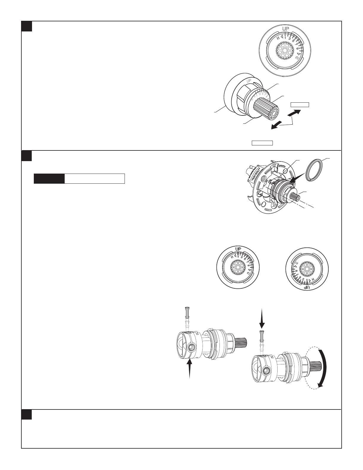
BACK TO BACK INSTALLATION (FIGURE 2, 3 & 3A)
• Remove CARTRIDGE (1).
Remove venturi tube by pushing it out. As shown in
FIGURE 3.
Rotate CARTRIDGE (1) 180˚ so that the Up text is
displayed on the bottom side. As shown in FIGURE 2.
Reinstall the venturi tube by pushing it in.
As shown in FIGURE 3A.
• Insert Cartridge back into the valve.
• Reassemble BONNET NUT (2) and hand tighten.
CARE INSTRUCTIONS:
DO: SIMPLY RINSE THE PRODUCT CLEAN WITH CLEAR WATER. DRY WITH A SOFT COTTON FLANNEL CLOTH.
DO NOT: DO NOT CLEAN THE PRODUCT WITH SOAPS, ACID, POLISH, ABRASIVES, HARSH CLEANERS, OR A
CLOTH WITH A COARSE SURFACE.
6
Remove HANDLE (see step 3 and reverse).
Remove ESCUTCHEON and CARTRIDGE CAP (see step 1 and reverse).
SERVICE
TO GAIN ACCESS TO VALVE FOR SERVICING
Figure 1.
1
3
2
Figure 2.
Standard
Back to Back
M965938 (8/18)
CAUTION
Turn off hot and cold water
supplies before beginning.
ROTATE 180°
Figure 3. Figure 3A.
PUSH UP
PUSH DOWN
5
By restricting HANDLE rotation and limiting the amount of hot water
allowed to mix with the cold, the HOT LIMIT SAFETY STOP (1)
reduces risk of accidental scalding. To set the maximum hot water
temperature of your faucet valve, adjust the setting on the HOT LIMIT
SAFETY STOP (1).
Turn CARTRIDGE STEM (2) to the OFF position (coldest setting) before
making adjustment to HOT LIMIT STOP (1). Pull forward and rotate
counterclockwise one number to limit hot water temperature.
Use NUMBERS (5) on CARTRIDGE (4) on HOT LIMIT STOP (1)
for indication.
ADJUST HOT LIMIT STOP
COLDER
(Larger Numbers)
1 2 3 4 5 6 7 8 9 10
HOTTER
(Smaller Numbers)
1 2 3 4 5 6 7 8 9 10
3
4
1
5
2
- 4 -- 4 -
M965938 (8/18)
Fluent
®
Pressure Balancing
Bath and Shower
Trim Kit
HOT LINE FOR HELP
For toll-free information and answers to your questions, call:
1 (800) 442-1902
Mon. - Fri. 8:00 a.m. to 8:00 p.m. EST
Saturday 10:00 a.m. to 4:00 p.m. EST
IN CANADA 1-800-387-0369
(TORONTO 1-905-306-1093)
Weekdays 8:00 a.m. to 7:00 p.m. EST
IN MEXICO 01-800-839-1200
MODEL NUMBERS
Replace the “YYY” with
appropriate finish code
POLISHED CHROME 002
BRUSHED NICKEL 295
LEGACY BRONZE 278
M970410-0070A
CARTRIDGE
M909349-YYY0A
DIAL PLATE
M907050-YYY0A
ESCUTCHEON CAP
8888009-YYY
DIVERTER SPOUT (Slip-on)
M970457-0070A
HANDLE ADAPTER KIT
M964928-YYY0A
HANDLE KIT
A919542-YYY0A
SHOWER ARM
060337-YYY0A
SHOWER ARM
FLANGE
1660604.YYY
SHOWER HEAD - 2.5 GPM
1660605.YYY
SHOWER HEAD - 1.8 GPM
078016-0020A
ESCUTCHEON SCREWS
M907813-YYY0A
ESCUTCHEON KIT
O f f
C
H
M954805-0070A
DEEP ROUGH-IN
KIT
PURCHASE SEPARATELY
TU186500
TU186501
TU186501XH
TU186501
TU186502
TU186507
TU186508
  • Page 1 1
  • Page 2 2
  • Page 3 3
  • Page 4 4

American Standard TU186500.002 Installation guide

Category
Sanitary ware
Type
Installation guide

Ask a question and I''ll find the answer in the document

Finding information in a document is now easier with AI