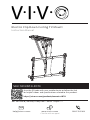
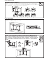
Vivo MOUNT-E-FD70 is an electric flip-down ceiling TV mount designed to provide a safe and secure way to mount your TV to the ceiling. It features a sturdy construction that can support TVs up to 77lbs (35kg) and comes with all the necessary hardware for installation. The mount allows you to easily lower your TV down from the ceiling for viewing and then raise it back up when you're finished. It also includes a remote control for added convenience, allowing you to adjust the TV's position without having to get up.
Vivo MOUNT-E-FD70 is an electric flip-down ceiling TV mount designed to provide a safe and secure way to mount your TV to the ceiling. It features a sturdy construction that can support TVs up to 77lbs (35kg) and comes with all the necessary hardware for installation. The mount allows you to easily lower your TV down from the ceiling for viewing and then raise it back up when you're finished. It also includes a remote control for added convenience, allowing you to adjust the TV's position without having to get up.


-
 1
1
-
 2
2
-
 3
3
-
 4
4
-
 5
5
-
 6
6
-
 7
7
-
 8
8


Vivo MOUNT-E-FD70 is an electric flip-down ceiling TV mount designed to provide a safe and secure way to mount your TV to the ceiling. It features a sturdy construction that can support TVs up to 77lbs (35kg) and comes with all the necessary hardware for installation. The mount allows you to easily lower your TV down from the ceiling for viewing and then raise it back up when you're finished. It also includes a remote control for added convenience, allowing you to adjust the TV's position without having to get up.
Ask a question and I''ll find the answer in the document
Finding information in a document is now easier with AI
Related papers
-
Vivo MOUNT-VW06 Assembly Instructions
-
-
-
-
-
-
Vivo MOUNT-VW100F User manual
-
-
-
Other documents
-
Philips MCD263/98 Quick Installation Guide
-
V I V O STAND-RACE1TV User manual
-
-
ITC 85606-SS Installation guide
-
ITC 69365 Installation guide
-
WALI PSM001 User manual
-
 Julian Bowen FIN004 Assembly Instructions
-
Ematic EMW222 Installation guide
-
Clinton Electronics CE-174C User manual
-
