1
C603RL 151214
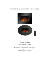
Remote Control
Electric Fire
Model C603RL
Instructions for Use, Installation & Maintenance
0104 095 52219

2
C603RL 151214
Parts Supplied
Fittings Supplied
Tools required
(not supplied)
Ref Description Illustration Qty
A Electric Fire
1
B Decorative Trim, Front and
Fret
1
C Spacer Frame
(Available as an option, not
supplied with all models)
(See Option 2, Page 4)
1
D Remote control
(With batteries)
1
Ref Description Illustration Qty
E Wood Screw
4
F Wall Plug
6
G Cable Kit 1
H Magnets 4
I Screw No 8 x ½
4
Electric Drill (Hammer action)
Masonry bit
Screwdriver (Crosshead)
Screwdriver (Straight head)
Pliers
FLAME
OFF
1 kw
SAFTEY 2 kw

3
C603RL 151214
Before You Start
Please read these instructions carefully before you start installation.
Check the pack and make sure you have all of the parts listed on page 2
.
When you are ready to start, make sure that you have the appropriate tools to hand, plenty of
space and a clean dry area for installation.
Check that the supply voltage on the rating label is in accordance with your electricity supply.
WARNING! THIS APPLIANCE MUST BE EARTHED
WARNING! This heater is not equipped with a device to control the room temperature. Do not
use this heater in small rooms when they are occupied by persons not capable of leaving the
room on their own, unless constant supervision is provided.
IMPORTANT: If a replacement plug is required, the existing plug may be cut off. Please
dispose of the plug carefully and follow the manufacturer’s instructions when fitting the new
plug. If required, a 15- Amp plug may be used.
WARNING! If the supply cord is damaged, the manufacturer, its service agent or a similarly
qualified person must replace it in order to avoid a hazard
.
FLUE: when fitted into a chimney opening, THE FLUE MUST BE BLOCKED to prevent any
draught affecting the operation of the heater fan unit. (A strong draught up the chimney may
cause intermittent operation of the overheat limit switch). DO NOT INSTALL THE
APPLIANCE IN AN EXISTING CHIMNEY OPENING UNTIL THE FLUE IS BLOCKED.
This electric fire is intended for normal indoor domestic use only.
DO NOT use the heater in the immediate surrounds of a bath, shower or swimming pool.
DO NOT locate this appliance on a thick pile carpet.
WARNING! To avoid overheating, do not cover the appliance. Do not operate the heater
with the canopy open (lowered).
DO NOT place clothing or objects immediately in front of the heater outlet. It may cause
overheating or cause objects to ignite.
DO NOT locate or install immediately below a socket outlet.
Children of less than 3 years should be kept away unless continuously supervised.
Children aged from 3 years and less than 8 years shall only switch on/off the appliance
provided that it has been placed or installed in its intended normal operating position and they
have been given supervision or instruction concerning use of the appliance in a safe way and
understand the hazards involved. Children aged from 3 years and less than 8 years shall not
plug in, regulate or clean the appliance or perform user maintenance.
CAUTION – Some parts of the product can become very hot and cause burns.
Particular attention has to be given where children and vulnerable people are present.

4
C603RL 151214
This appliance can be used by children aged from 8 years and above and persons with
reduced physical, sensory or mental capabilities or lack experience and knowledge if they
have been given supervision or instruction concerning use of the appliance in a safe way and
understand the hazards involved. Children shall not play with the appliance. Cleaning and
user maintenance shall not be made by children without supervision.
This appliance may be fitted with a moulded plug supplied with a 13- Amp fuse. Always
replace the 13- Amp fuse with one approved by ASTA to the current issue of BS 1362. The
fuse cover is to be re-fitted after changing the fuse. If the fuse cover is lost, do not use the
plug. Replacement fuse covers may be obtained from a reputable electrical spares retailer.
In order to achieve the realistic flame effect and provide efficient heating, fans are used within
this appliance. There may, as a result, be some residual noise when these are in operation –
this is normal.
Please retain these instructions for future reference!
Installation
The mains plug must be accessible after installation.
Ensure adequate space is maintained for the routing of the supply cord.
This appliance has three installation options: -
Option 1: Wall or Back Panel Fixing (Screw method)
For fitting the appliance into a blocked flue:
Offer the firebox into the opening.
Mark the holes provided, indicated by the four arrows (Fig. 1).
Drill, plug and screw the firebox to the wall or back panel.
Ensure a good seal is made between the firebox and wall or back panel.
Option 2: Full Spacer
Offer the spacer frame (available as an option if not supplied) up to the wall ensuring that the
wider of the two internal faces is against the wall (Fig. 2).
Ensure that the frame is square
and true, mark and drill the wall using a
masonry bit and fix into position using screws (E) & the wall plugs (F) supplied.
Offer the appliance up to the frame and screw into position using the screws (I) supplied.
Fig. 1
Fixing hole
Fixing hole
Fixing hole
Fixing hole

5
C603RL 151214
Wire cable fixing should be used with stone or marble panel which could fracture
if drilled. (See Fig. 3)
Option 3: Wire cable fixing (G)
Retaining
Bush
Screw eye
Min Height
300mm
Max Height
330mm
420mm apart
Two `screw eyes’ are fixed
to the rear of the opening
with wall plugs.
Min height from base of
opening – 300mm
Max height from base of
opening – 330mm
`Screw eyes’ to be 420mm
apart
Cable fixing holes
Fig. 3
Spacer fixing
holes
Fire fixing holes
Fig. 2

6
C603RL 151214
Fix two `screw eyes’ to the rear of the opening. (Note the minimum and maximum height
restrictions in the diagram above). Thread the wire cable through the top hole located on the
side of the fire trim frame. Thread through the `screw eye’ and then through the bottom hole
located on the side of the trim frame.
(Repeat for opposite side).
Pull the wire cable and carefully push the firebox into a central position in the opening.
Thread each end of the wire cable through the retaining bush. Adjust the cable and tighten
the retaining bush to ensure that a good seal is made between the firebox and back panel.
Flat wall fix
(FOR REFERENCE ONLY)
Flat wall fix is suitable for a mantel with a minimum 2½” (65mm) internal rebate; remove the
internal rebate from the mantel (Fig. 4).
Place the back panel into position and offer the appliance up to the opening in the back panel.
Offset the panel from the wall so that it is situated against the rear trim frame of the appliance;
use suitable material to bridge the space between the back panel and the wall (Fig. 4).
Place the mantel into position and secure to the wall using suitable screws & wall plugs.
(PLEASE REFER TO MANUFACTURER’S INSTRUCTIONS FOR INSTALLATION OF
HEARTH & BACK PANEL).
Existing wall
Space to be bridged
Back panel
Fig. 4
Internal rebate

7
C603RL 151214
Trim location
Place each of the four magnets (H) onto the location brackets (Fig. 5). Some trim options
require extension clips or extra magnets. Remove any protective film from the trim. Fit the
trim (B) ensuring positive location against the magnets (Fig. 6).
Place front and fret central to the trim (Fig. 7 & 8).
Front & Frets
(several styles and finishes are available)
Fig. 5
Magnet
location
brackets
Fig. 6
Trim
Figs. 7 & 8

8
C603RL 151214
Care and Use
Fire operation
This appliance has both manual and remote operation.
This appliance is not intended for use by persons (including children) with reduced
physical, sensory or mental capabilities, or lack of experience and knowledge, unless they
have been given supervision or instruction concerning use of the appliance by a person
responsible for their safety.
For safety and to save compromising the visual look of this appliance the controls have
been located behind the canopy. To access the controls press the top of the canopy as
shown in Fig. 9. The canopy will open out from the top to reveal the controls. Close the
canopy once the controls have been set.
DO NOT leave children unsupervised near the appliance when in use.
DO NOT operate the appliance with canopy in the open position (Fig. 9).
Mains Power Switch
(Fig. 9)
Press for power on. The flame effect will come on.
Press again for power off. All functions will be switched off.
Always switch power off when not required to operate.
Manual Heat Operation (Fig. 10)
Press
button.
Left hand indicator will glow, allowing selection of heat setting.
For half heat setting (1kW) press the right hand button once. The right hand indicator glows
green.
For full heat setting (2kW) press the right hand button again. The indicator glows red.
To return to flame effect only press the right hand button until the indicator lamp goes off.
Pressing
again switches any heat off, both indicators go off. The flame effect will stay on.
Press here to open Press here to close Open position
Fig. 9
Power Switch

9
C603RL 151214
Remote Control Operation (Fig. 11)
To prevent accidental heating operation the “Power” button on the remote control must be
pressed and held down whilst activating the “1000W” or “2000W” buttons.
For half heat setting (1kW) hold down “Power” and press “1000W” button.
For full heat setting (2kW) hold down “Power” and press “2000W” button.
To return to flame effect only, hold down the “Power” button and press the “Flame” button.
This will cancel heating leaving the light and flame flicker effect on.
Alternatively, to cancel heat operation at any time press the
button
Minimum operating distance 1 metre from appliance
Maximum operating distance 5 metres from appliance
Maximum operating height 1 metre
If the remote control is not functioning, check the fire using the manual controls.
Replacement 1.5V AAA batteries are widely available. Used batteries should not be disposed
of with general waste, but should be returned to designated collection points. Contact your
retailer, council or local authority for further information.
Note: The flame effect can only be switched off by using the power switch (Fig. 9) or by
disconnecting the appliance from the mains supply.
Flame (no heat)
1000W(1kW)
2000W(2kW) Power
Fig. 11
Fig. 10
Indicator lamps
Buttons
Enable heat
1 kW & 2 kW heat settings

10
C603RL 151214
Replacing the Lamp
The lamp consists of a specially designed array of light emitting diodes (LED’s). It is not a
user serviceable component and can only be repaired by a service agent.
Thermal Cut-Out Operation
If the room heater fails to operate, the thermal protector may have operated and reset the
appliance to NO HEAT status. In this event, allow the appliance to cool, investigate the
reason, remove any item covering the heater or restricting airflow and operate the controls
again to restore operation. The flame effect may go out briefly or may stay on.
Cleaning and Servicing
For general cleaning, use a soft clean duster or a soft brush, a vacuum may be used for the
coal bed.
The decorative trims for this appliance have a protective coating. Remove from the appliance
before cleaning with warm soapy water and a soft cloth. NEVER USE SCOURERS,
ABRASIVES OR CHEMICAL CLEANERS.
Before commencing work, turn off appliance and remove plug from socket.
Servicing is only to be carried out by competent/qualified persons.
Replacement of supply cord should only be carried out by the manufacturer, its service
agent or a similarly qualified person in order to avoid a hazard.
Disposal of appliance
This appliance is constructed from materials which are fully RoHS compliant.
This appliance is marked in accordance with the European Directive 2012/19/EC on Waste
Electrical and Electronic Equipment (WEEE). At end of life this product should be recycled
and not disposed in household waste. Contact your retailer, council or local authority for
further information.
EEE producer registration no. WEE/GG0057TS

11
C603RL 151214
Technical data
Standard
( Fig. 12 )
Optional
Spacer Fitted
( Fig. 13 )
Width at rear ( A ) 370mm 475mm
Overall width ( B ) 475mm 475mm
Overall height ( C ) 595mm 595mm
Height at rear ( D ) 540mm 595mm
Depth from fixing plane ( E ) 65mm N/A
Voltage 220-240~ 220-240~
Frequency 50Hz 50Hz
Fuse 13 Amp 13 Amp
Minimum heat output (low) 1000 Watts
1000 Watts
Maximum heat output (high) 2000 Watts
2000 Watts
Consumption of flicker unit 10 Watts 10 Watts
Approx. length of mains cable
1.6m 1.55m
A
A
E
C
B
Fig. 13
Fig. 12
D
D

12
C603RL 151214
Spare Parts List
Trim options and other spares items are available on request.
In the event that you may require service, spares or technical information, please contact us
at: -
Telephone
Customer Service 01422 203963
Service Engineer (0800Repair)* 0344 8797422
*Calls charged at basic rate.
PART DESCRIPTION
CROSSLEE PART No.
QTY
Magnet (manufacturer’s part no. N30H) 42561 4
Remote Handset 0104 092 40291 1
Spacer Frame 0104 075 33464 1
CROSSLEE plc
Halifax
West Yorkshire
HX3 8DE
/