Page is loading ...

DVS 100 and DVS150
Digital Video Scalers
68-459-01
Printed in USA

This symbol is intended to alert the user of important operating and maintenance
(servicing) instructions in the literature provided with the equipment.
This symbol is intended to alert the user of the presence of uninsulated dangerous
voltage within the product's enclosure that may present a risk of electric shock.
Caution
Read Instructions • Read and understand all safety and operating instructions before using the
equipment.
Retain Instructions • The safety instructions should be kept for future reference.
Follow Warnings • Follow all warnings and instructions marked on the equipment or in the user
information.
Avoid Attachments • Do not use tools or attachments that are not recommended by the equipment
manufacturer because they may be hazardous.
Warning
Power sources • This equipment should be operated only from the power source indicated on the
product. This equipment is intended to be used with a main power system with a grounded
(neutral) conductor. The third (grounding) pin is a safety feature, do not attempt to bypass or
disable it.
Power disconnection • To remove power from the equipment safely, remove all power cords from
the rear of the equipment, or the desktop power module (if detachable), or from the power
source receptacle (wall plug).
Power cord protection • Power cords should be routed so that they are not likely to be stepped on or
pinched by items placed upon or against them.
Servicing • Refer all servicing to qualified service personnel. There are no user-serviceable parts
inside. To prevent the risk of shock, do not attempt to service this equipment yourself because
opening or removing covers may expose you to dangerous voltage or other hazards.
Slots and openings • If the equipment has slots or holes in the enclosure, these are provided to
prevent overheating of sensitive components inside. These openings must never be blocked by
other objects.
Lithium battery • There is a danger of explosion if battery is incorrectly replaced. Replace it only with
the same or equivalent type recommended by the manufacturer. Dispose of used batteries
according to the manufacturer's instructions.
Ce symbole sert à avertir l’utilisateur que la documentation fournie avec le matériel
contient des instructions importantes concernant l’exploitation et la maintenance
(réparation).
Ce symbole sert à avertir l’utilisateur de la présence dans le boîtier de l’appareil de
tensions dangereuses non isolées posant des risques d’électrocution.
Attention
Lire les instructions• Prendre connaissance de toutes les consignes de sécurité et d’exploitation avant
d’utiliser le matériel.
Conserver les instructions• Ranger les consignes de sécurité afin de pouvoir les consulter à l’avenir.
Respecter les avertissements • Observer tous les avertissements et consignes marqués sur le matériel ou
présentés dans la documentation utilisateur.
Eviter les pièces de fixation • Ne pas utiliser de pièces de fixation ni d’outils non recommandés par le
fabricant du matériel car cela risquerait de poser certains dangers.
Avertissement
Alimentations• Ne faire fonctionner ce matériel qu’avec la source d’alimentation indiquée sur
l’appareil. Ce matériel doit être utilisé avec une alimentation principale comportant un fil de
terre (neutre). Le troisième contact (de mise à la terre) constitue un dispositif de sécurité :
n’essayez pas de la contourner ni de la désactiver.
Déconnexion de l’alimentation• Pour mettre le matériel hors tension sans danger, déconnectez tous
les cordons d’alimentation de l’arrière de l’appareil ou du module d’alimentation de bureau (s’il
est amovible) ou encore de la prise secteur.
Protection du cordon d’alimentation • Acheminer les cordons d’alimentation de manière à ce que
personne ne risque de marcher dessus et à ce qu’ils ne soient pas écrasés ou pincés par des objets.
Réparation-maintenance • Faire exécuter toutes les interventions de réparation-maintenance par un
technicien qualifié. Aucun des éléments internes ne peut être réparé par l’utilisateur. Afin
d’éviter tout danger d’électrocution, l’utilisateur ne doit pas essayer de procéder lui-même à ces
opérations car l’ouverture ou le retrait des couvercles risquent de l’exposer à de hautes tensions
et autres dangers.
Fentes et orifices • Si le boîtier de l’appareil comporte des fentes ou des orifices, ceux-ci servent à
empêcher les composants internes sensibles de surchauffer. Ces ouvertures ne doivent jamais
être bloquées par des objets.
Lithium Batterie • Il a danger d'explosion s'll y a remplacment incorrect de la batterie. Remplacer
uniquement avec une batterie du meme type ou d'un ype equivalent recommande par le
constructeur. Mettre au reut les batteries usagees conformement aux instructions du fabricant.
Safety Instructions • English
Consignes de Sécurité • Français
Precautions
Sicherheitsanleitungen • Deutsch
Este símbolo se utiliza para advertir al usuario sobre instrucciones importantes de
operación y mantenimiento (o cambio de partes) que se desean destacar en el
contenido de la documentación suministrada con los equipos.
Este símbolo se utiliza para advertir al usuario sobre la presencia de elementos con
voltaje peligroso sin protección aislante, que puedan encontrarse dentro de la caja
o alojamiento del producto, y que puedan representar riesgo de electrocución.
Precaucion
Leer las instrucciones • Leer y analizar todas las instrucciones de operación y seguridad, antes de usar
el equipo.
Conservar las instrucciones • Conservar las instrucciones de seguridad para futura consulta.
Obedecer las advertencias • Todas las advertencias e instrucciones marcadas en el equipo o en la
documentación del usuario, deben ser obedecidas.
Evitar el uso de accesorios • No usar herramientas o accesorios que no sean especificamente
recomendados por el fabricante, ya que podrian implicar riesgos.
Advertencia
Alimentación eléctrica • Este equipo debe conectarse únicamente a la fuente/tipo de alimentación
eléctrica indicada en el mismo. La alimentación eléctrica de este equipo debe provenir de un
sistema de distribución general con conductor neutro a tierra. La tercera pata (puesta a tierra) es
una medida de seguridad, no puentearia ni eliminaria.
Desconexión de alimentación eléctrica • Para desconectar con seguridad la acometida de
alimentación eléctrica al equipo, desenchufar todos los cables de alimentación en el panel trasero
del equipo, o desenchufar el módulo de alimentación (si fuera independiente), o desenchufar el
cable del receptáculo de la pared.
Protección del cables de alimentación • Los cables de alimentación eléctrica se deben instalar en
lugares donde no sean pisados ni apretados por objetos que se puedan apoyar sobre ellos.
Reparaciones/mantenimiento • Solicitar siempre los servicios técnicos de personal calificado. En el
interior no hay partes a las que el usuario deba acceder. Para evitar riesgo de electrocución, no
intentar personalmente la reparación/mantenimiento de este equipo, ya que al abrir o extraer las
tapas puede quedar expuesto a voltajes peligrosos u otros riesgos.
Ranuras y aberturas • Si el equipo posee ranuras o orificios en su caja/alojamiento, es para evitar el
sobrecalientamiento de componentes internos sensibles. Estas aberturas nunca se deben obstruir
con otros objetos.
Batería de litio • Existe riesgo de explosión si esta batería se coloca en la posición incorrecta. Cambiar
esta batería únicamente con el mismo tipo (o su equivalente) recomendado por el fabricante.
Desachar las baterías usadas siguiendo las instrucciones del fabricante.
Instrucciones de seguridad • Español
Dieses Symbol soll dem Benutzer in der im Lieferumfang enthaltenen
Dokumentation besonders wichtige Hinweise zur Bedienung und Wartung
(Instandhaltung) geben.
Dieses Symbol soll den Benutzer darauf aufmerksam machen, daß im Inneren des
Gehäuses dieses Produktes gefährliche Spannungen, die nicht isoliert sind und
die einen elektrischen Schock verursachen können, herrschen.
Achtung
Lesen der Anleitungen • Bevor Sie das Gerät zum ersten Mal verwenden, sollten Sie alle Sicherheits-und
Bedienungsanleitungen genau durchlesen und verstehen.
Aufbewahren der Anleitungen • Die Hinweise zur elektrischen Sicherheit des Produktes sollten Sie
aufbewahren, damit Sie im Bedarfsfall darauf zurückgreifen können.
Befolgen der Warnhinweise • Befolgen Sie alle Warnhinweise und Anleitungen auf dem Gerät oder in
der Benutzerdokumentation.
Keine Zusatzgeräte • Verwenden Sie keine Werkzeuge oder Zusatzgeräte, die nicht ausdrücklich vom
Hersteller empfohlen wurden, da diese eine Gefahrenquelle darstellen können.
Vorsicht
Stromquellen • Dieses Gerät sollte nur über die auf dem Produkt angegebene Stromquelle betrieben
werden. Dieses Gerät wurde für eine Verwendung mit einer Hauptstromleitung mit einem
geerdeten (neutralen) Leiter konzipiert. Der dritte Kontakt ist für einen Erdanschluß, und stellt
eine Sicherheitsfunktion dar. Diese sollte nicht umgangen oder außer Betrieb gesetzt werden.
Stromunterbrechung • Um das Gerät auf sichere Weise vom Netz zu trennen, sollten Sie alle
Netzkabel aus der Rückseite des Gerätes, aus der externen Stomversorgung (falls dies möglich
ist) oder aus der Wandsteckdose ziehen.
Schutz des Netzkabels • Netzkabel sollten stets so verlegt werden, daß sie nicht im Weg liegen und
niemand darauf treten kann oder Objekte darauf- oder unmittelbar dagegengestellt werden
können.
Wartung • Alle Wartungsmaßnahmen sollten nur von qualifiziertem Servicepersonal durchgeführt
werden. Die internen Komponenten des Gerätes sind wartungsfrei. Zur Vermeidung eines
elektrischen Schocks versuchen Sie in keinem Fall, dieses Gerät selbst öffnen, da beim Entfernen
der Abdeckungen die Gefahr eines elektrischen Schlags und/oder andere Gefahren bestehen.
Schlitze und Öffnungen • Wenn das Gerät Schlitze oder Löcher im Gehäuse aufweist, dienen diese
zur Vermeidung einer Überhitzung der empfindlichen Teile im Inneren. Diese Öffnungen dürfen
niemals von anderen Objekten blockiert werden.
Litium-Batterie • Explosionsgefahr, falls die Batterie nicht richtig ersetzt wird. Ersetzen Sie
verbrauchte Batterien nur durch den gleichen oder einen vergleichbaren Batterietyp, der auch
vom Hersteller empfohlen wird. Entsorgen Sie verbrauchte Batterien bitte gemäß den
Herstelleranweisungen.

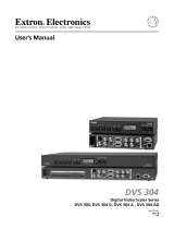
Quick Start — DVS 100 and DVS 150
Installation
Step 1
Install the four rubber feet on the
bottom of the scaler (1A), or mount the
scaler in a rack (1B).
Step 2
Turn off power to the input and output
devices, and unplug their power cords.
Step 3
Attach the scaler to the input devices.
Input options (3) are:
Composite video (input 1)
Component video (input 2)
S-video (input 3)
RGB pass-thru (input 4; DVS 150
only)
Step 4
Attach the scaler to the output devices.
Output options (4) are:
RGsB (connected to R, G, and B)
RGBS (connected to R, G, B, and S)
RGBHV (connected to R, G, B, H,
and V)
VGA/XGA/SVGA/SXGA
(connected to RGB output connector)
Step 5
Plug the scaler, input device, and
output device into a grounded AC
source, and turn on the input and
output devices.
Step 6
Use the LCD menu screens to
configure the scaler (see the next
page).
Rubber feet
bottom side
(4 plcs)
(2) 4-40 x 1/8" screws
Use 2 mounting holes on
opposite corners
False front panel
uses 2 front holes
or
1A 1B
R
A
T
E
V
S
H
I
F
T
H
S
H
I
F
T
C
O
N
T
R
A
S
T
B
R
I
T
T
I
N
T
C
O
L
O
R
1
2
3
D
V
S
1
0
0
D
I
G
I
T
A
L
V
I
D
E
O
S
C
A
L
E
R
I
N
P
U
T
Input/Output Devices
INPUTS
R-Y
50/60 Hz
100-240 VAC .3A MAX
1
2
34
Y
B-Y
H
R
V
G
S
B
VIDEO
REMOTE
RGB
RGB
PASS-THRU
S-VIDEO
OUTPUTS
RS-232 Control
RS-232 Control
INPUTS
R-Y
50/60 Hz
100-240V 0.1A
1
2
3
Y
B-Y
H
R
V
G
S
B
VID
REMOTE
RGB OUT
OUTPUTS
S-VIDEO
DVS 150
DVS 100
INPUT
OUTPUT
INPUT
OUTPUT
or or
CRT ProjectorLCD Projector
DLP Projector
HDTV Plasma
or or
CRT ProjectorDLP Projector
DLP Projector
HDTV Plasma
Laptop
Computer
DVD Player
DSS Receiver
DVD Player
DSS Receiver
Laserdisc Player
Laserdisc Player
Composite Video
(Input 1)
RGsB RGBS RGBHV
Component Video
(Input 2)
S-video
(Input 3)
RGB Output
RGB
Pass-Thru
(Input 4; DVS 150 only)
R-Y
1
2
3
Y
B-Y
H
R
V
G
S
B
H
R
V
G
S
B
H
R
V
G
S
B
VID
R-Y
1
2
3
Y
B-Y
VID
R-Y
1
2
3
Y
B-Y
VID
3
4

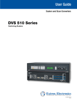
Quick Start — DVS 100 and DVS 150, cont’d
Configuring the Scaler
Configuring the scaler: Press the input and rate buttons simultaneously, and hold them for two
seconds.
Stepping through the LCD display menus: Press the input selection button.
Changing a selection: Turn the adjustment knob while the menu is displayed.
Exiting the menus: Press the input selection button while the Detail menu is displayed, or don’t press
any buttons or turn any knobs for eight seconds.
AUTOSW — Choose whether the DVS automatically selects the active input.
On: The DVS selects the active input automatically. Off: You select the input manually.
TOPBLANK — Add or remove additional blanking lines at the top of the image.
BOTBLANK — Add or remove additional blanking lines at the bottom of the image.
H-SYNC — Change the polarity of the horizontal sync signal to allow any projector to distinguish the
DVS 100 or DVS 150 input from a standard RGB input.
+: Sets the horizontal sync polarity to positive. -: Sets the horizontal sync polarity to negative.
V-SYNC — Change the polarity of the vertical sync signal to allow any projector to distinguish the
DVS 100 or DVS 150 input from a standard RGB input.
+: Sets the vertical sync polarity to positive. -: Sets the vertical sync polarity to negative.
SOG — Set the sync output format.
Yes: Sync on green (RGsB) output. No: RGBS or RGBHV output (based on unit cabling).
STILL — Enhance output for still or motion video.
On: Enhanced image for still video and text. Off: Enhanced image for motion video.
DETAIL — Apply a filter to improve image detail.
1: Low level of detail. 2: Medium level of detail. 3: High level of detail.
Operation
Choosing the input source: Press the input selection button until the desired input LED lights.
If input 4 (RGB pass-through) of the DVS 150 is selected, you cannot make any of the following
adjustments.
Adjusting the image: Press the button for the adjustment, and rotate the adjustment knob until the
desired result is achieved.
Choosing the output rate: Press and hold the rate button for two seconds, and then rotate the
adjustment knob until the desired rate appears in the LCD display. Options are:
640x480 (VGA), 60/75 Hz 848x480 (plasma), 60 Hz 1280x768 (plasma), 56 Hz 480p (HDTV)
800x600 (SVGA), 60/75 Hz 852x480 (plasma), 60/75 Hz 1280x1024 (SXGA), 60 Hz 720p (HDTV)
832x624 (Mac), 60/75 Hz 1024x768 (XGA), 60/75 Hz 1360x765 (plasma), 60 Hz 1080p (HDTV)
Activating freeze mode: Issue the RS-232 freeze mode command.
Deactivating freeze mode: Press the input selection button or issue an RS-232 command.
Restoring default picture control settings (active input): Press and hold the input selection button for
two seconds.
Restoring all settings to factory defaults: Press and hold the input selection button while attaching
the AC power cord.

1-i
DVS 100 and DVS 150 Table of Contents
Chapter 1 • Introduction .......................................................................................... 1-1
About the Scaler .................................................................................................... 1-2
Features ..................................................................................................................... 1-2
Chapter 2 • Installation ............................................................................................. 2-1
Rear Panel Features .............................................................................................. 2-2
Installation ............................................................................................................... 2-3
Overview .............................................................................................................. 2-3
Mounting the scaler ............................................................................................ 2-3
Installing the rubber feet .................................................................................... 2-4
Cabling ................................................................................................................. 2-5
Front Panel Features............................................................................................. 2-6
Configuring the Scaler......................................................................................... 2-6
Configuration settings ........................................................................................ 2-7
Chapter 3 • Operation ................................................................................................ 3-1
Front Panel Operations........................................................................................ 3-2
Default screens .................................................................................................... 3-2
Choosing the input source .................................................................................. 3-2
Adjusting an image ............................................................................................. 3-2
Choosing the output rate ................................................................................... 3-3
Freeze mode ........................................................................................................ 3-4
Executive mode ................................................................................................... 3-4
Resetting the scaler ............................................................................................. 3-4
Channel reset .................................................................................................. 3-4
System reset .................................................................................................... 3-5
Chapter 4 • Serial Communication ..................................................................... 4-1
RS-232 Programmer’s Guide .............................................................................. 4-3
DVS initiated messages ....................................................................................... 4-3
DVS error response .............................................................................................. 4-3
Using the command/response table ................................................................... 4-3
Command/response table ................................................................................... 4-4
Remote Contact Closure Operation................................................................ 4-3
Control Software for Windows ........................................................................ 4-5
Installing the Software ........................................................................................ 4-5
Using the Software.............................................................................................. 4-6
Table of Contents

Table of Contents, cont’d
ii DVS 100 and DVS 150 Table of Contents
Chapter 5 • Troubleshooting .................................................................................. 5-1
Operating Problems .............................................................................................. 5-2
Appendix A • Specifications .................................................................................. A-1
Appendix B • Reference Information ................................................................B-1
Part Numbers ..........................................................................................................B-2
DVS 100 and DVS 150 part numbers .................................................................. B-2
Related part numbers ......................................................................................... B-2
BNC cables ...........................................................................................................B-2
Glossary ..................................................................................................................... B-3
68-459-01 C
Printed in the USA
04 00

1
DVS 100 and DVS 150
Chapter One
Introduction
About the Scaler
Features

Introduction, cont’d
DVS 100 and DVS 150 Introduction1-2
About the Scaler
Each DVS 100 and DVS 150 digital video scaler allows analog video
signals (composite video, S-video, and component video) to be
displayed on a device with a fixed resolution and aspect ratio, such as an
LCD (liquid crystal display) projector, DLP (digital light processing)
projector, or plasma display.
DVS 150 includes a 15-pin HD RGB pass-through connector for RGB
input. Video signals coming into the scaler from this connector are not
scaled. Instead, they are passed directly to the ouputs.
Features
• Autosave — Automatically stores adjustments and uses the control
settings associated with the selected input.
• Autoswitch mode — Automatically selects the active input device. If
more than one input device is on, the device with the highest
video quality is selected.
• Blanking — Allows noise or unwanted information, such as tape head
switching and closed captioning, to be eliminated from the top
and bottom of the display.
• Dual output connectors — Allow you to connect and run two output
devices simultaneously.
• Executive mode — Locks out all front-panel image adjustment
functions except input selection. When executive mode is active,
all image adjustments are available through RS-232 commands.
• Freeze mode — Locks the output display to the current image.
• Inputs — Includes three BNC connectors for component video, one
BNC connector for composite video, and one 4-pin mini-DIN
connector for S-video. The DVS 150 also includes one 15-pin HD
connector for RGB pass-through input.
• Multiple control methods — Allow you to make adjustments by
pressing a button on the front panel, choosing options from a
menu, sending an RS-232 command from a computer, or using a
remote contact closure control.
• Outputs — Outputs video as RGB, RGsB, RGBS, and RGBHV. BNC
connectors and a 15-pin HD connector are provided.
Introduction

1-3DVS 100 and DVS 150 Introduction
• Output resolutions — Supports the following output resolutions:
• 640 x 480 (VGA) at 60 or 75 Hz (Hertz)
• 800 x 600 (SVGA) at 60 or 75 Hz
• 832 x 624 (Macintosh) at 60 or 75 Hz
• 848 x 480 (plasma) at 60 Hz
• 852 x 480 (plasma) at 60 or 75 Hz
• 1024 x 768 (XGA) at 60 or 75 Hz
• 1280 x 768 (plasma) at 56 Hz
• 1280 x 1024 (SXGA) at 60 Hz
• 1360 x 765 (plasma) at 60 Hz
• 480p (HDTV)
• 720p (HDTV)
• 1080p (HDTV)
• Power supply — Includes an internal, 100-240VAC, 50/60 Hz, auto-
switchable power supply.
• Precise image processing — Provides the latest in motion compensation,
which produces motion images that are free of “jaggies”; a three-
line adaptive comb filter, which eliminates chroma crawl; and a quad
standard decoder, which ensures compatibility with NTSC (National
Television Standards Committee) 3.58, NTSC 4.43, SECAM
(sequential couleur avec mémoire), and PAL (phase alternate line)
video standards.
• Software-based configuration — Allows you to configure the scaler
through menu controls, simplifying installation.
• Switchable sync polarities — Allow you to manually set the
horizontal and vertical sync polarities, to allow the output device
to store DVS input as a unique input.

Introduction, cont’d
DVS 100 and DVS 150 Introduction1-4

2
DVS 100 and DVS 150
Chapter Two
Installation
Rear Panel Features
Installation
Front Panel Features
Configuring the Scaler

Installation, cont’d
DVS 100 and DVS 150 Installation2-2
Rear Panel Features
Figure 1 — DVS 100 rear panel
Figure 2 — DVS 150 rear panel
1
AC power connector — Standard AC power connector attaches
the scaler to any power source from 100VAC to 240VAC, operating
at 50 Hz or 60 Hz.
2
Composite video input connector — One BNC female connector
for composite video input.
3
Component video input connectors — Three BNC female
connectors for component (R-Y, B-Y, Y) video input.
4
S-video input connector — One 4-pin mini-DIN female connector
for S-video input.
5
RGB output connector — One 15-pin HD female RGB connector
for the output projector.
You can install and run two output devices simultaneously, one
using BNC connectors, and the other using the RGB connector.
6
Output connectors — BNC female connectors for RGsB (sync on
green), RGBS (composite sync), or RGBHV output.
7
RS-232/contact closure remote connector — One 9-pin D female
connector that allows you to attach a computer or another device,
such as a keypad or other contact closure device, for remote
control of the scaler.
8
RGB pass-thru connector (DVS 150 only) — One 15-pin HD
female RGB connector for input. The signal from the input device
is passed through to the output connectors without being scaled.
Installation
INPUTS
R-Y
50/60 Hz
100-240V 0.3A
1
2
3
Y
B-Y
H
R
V
G
S
B
VIDEO
REMOTE
RGB
OUTPUTS
S-VIDEO
1
2
3
4
5
6
7
INPUTS
R-Y
50/60 Hz
1
2
34
Y
B-Y
H
R
V
G
S
B
VIDEO
REMOTE
RGB
RGB
S-VIDEO
OUTPUTS
1
2
3
4
6
7
5
8
100-240V 0.3A

2-3DVS 100 and DVS 150 Installation
Installation
Overview
To install and set up the DVS 100 or DVS 150, follow these basic steps:
1
If desired, mount the scaler in a rack (see “Mounting the scaler”
below). Otherwise, install the rubber feet (see “Installing the
rubber feet” on page 2-4).
2
Turn off power to the input and output devices, and unplug the
power cables from them.
3
Attach the scaler to the input devices and the output devices. See
“Cabling” on page 2-5.
4
Plug the scaler, input devices, and output devices into a grounded
AC source.
5
Turn on the input and output devices.
6
Use the LCD menu screens to configure the scaler. See
“Configuring the Scaler” on page 2-7.
7
The image from the input device should appear on the output
device. If it does not, double check steps 3 and 4 and make
adjustments as needed, and then see “Operating Problems” on
page 5-2.
Mounting the scaler
Each DVS 100 and DVS 150 ships with four uninstalled rubber feet. If
you are going to rack mount the unit, do so before cabling it, and do not
install the rubber feet. If you are not rack mounting the scaler, skip to
“Installing the rubber feet” on page 2-4.
The DVS 100 or DVS 150 can be rack mounted using one side of an
optional 19” 1U Universal Rack Shelf (Extron part # 60-190-01).
To rack mount the scaler, do the following:
1. If rubber feet were previously installed on the bottom of the case,
remove them.
2. Mount the scaler on the rack shelf as shown in figure 3. Use two
4-40 x 1/8” screws in opposite (diagonal) corners to secure the case
to the shelf.

Installation, cont’d
DVS 100 and DVS 150 Installation2-4
Rubber Feet
Bottom Side (4 Plcs)
R
A
T
E
V
S
H
IF
T
H
S
H
IF
T
C
O
N
T
R
A
S
T
B
R
IT
T
IN
T
C
O
L
O
R
1
2
3
DVS 100
D
IG
IT
A
L
V
ID
E
O
S
C
A
L
E
R
IN
PU
T
Figure 3 — Mounting the scaler
Installing the rubber feet
The scaler ships with four uninstalled rubber feet. Install the rubber feet
only if you are not rack mounting the scaler. To install the rubber feet,
do the following:
1. Turn the scaler upside down and place it on a flat surface.
2. Remove the protective backing from a rubber foot.
3. Place the rubber foot on one corner of the scaler as shown in figure
4, and press it into place.
Position the rubber foot carefully before pressing it into place. It is
difficult to move the foot after it is in place.
Figure 4 — Installing the rubber feet
4. Repeat steps 2 and 3 to install a rubber foot on each of the
remaining corners of the scaler.
5. Turn the scaler right side up and place it in the desired location.
(2) 4-40 x 1/8" Screws
Use 2 mounting holes on
opposite corners
False front panel
uses 2 front holes
R
A
T
E
V
S
H
I
F
T
H
S
H
I
F
T
C
O
N
T
R
A
S
T
B
R
I
T
T
I
N
T
C
O
L
O
R
1
2
3
DVS 100
D
I
G
I
T
A
L
V
I
D
E
O
S
C
A
L
E
R
I
N
P
U
T

2-5DVS 100 and DVS 150 Installation
Cabling
The scaler can connect to input devices that produce composite video,
S-video, or component video, and to output devices, such as LCD
projectors, DLP displays, or plasma displays. The DVS 150 can also
connect to input devices that produce RGB video via the RGB pass-
through connector.
To cable the scaler, complete the following steps. Use figure 5 as a
general guide.
Figure 5 — Cabling the scaler
1. Attach the input device (or devices) to the scaler. Figure 6 shows
each of the connection options.
Figure 6 — Input connections
You can attach up to three input devices, one each of composite
video, S-video, and component video. You can also connect an
RGB input device, for pass-through to the output, to the DVS 150.
You can select among the input sources via the input selection
switch on the front panel.
If there is no video input, the LCD displays “No Source”.
2. Use BNC connectors or a 15-pin HD connector to connect the scaler
to the output device. Figure 7 shows each of the connection
options.
Figure 7 — Output connections
INPUTS
R-Y
50/60 Hz
100-240 VAC .3A MAX
1
2
34
Y
B-Y
H
R
V
G
S
B
VIDEO
REMOTE
RGB
RGB
PASS-THRU
S-VIDEO
OUTPUTS
RS-232 Control
RS-232 Control
INPUTS
R-Y
50/60 Hz
100-240V 0.1A
1
2
3
Y
B-Y
H
R
V
G
S
B
VID
REMOTE
RGB OUT
OUTPUTS
S-VIDEO
DVS 150
DVS 100
INPUT
OUTPUT
INPUT
OUTPUT
or or
CRT ProjectorLCD Projector
DLP Projector
HDTV Plasma
or or
CRT ProjectorDLP Projector
DLP Projector
HDTV Plasma
Laptop
Computer
DVD Player
DSS Receiver
DVD Player
DSS Receiver
Laserdisc Player
Laserdisc Player
Composite Video
(Input 1)
Component Video
(Input 2)
S-video
(Input 3)
RGB
Pass-Thru
(Input 4; DVS 150 only)
R-Y
1
2
3
Y
B-Y
VID
R-Y
1
2
3
Y
B-Y
VID
R-Y
1
2
3
Y
B-Y
VID
RGsB RGBS RGBHV
RGB Output
H
R
V
G
S
B
H
R
V
G
S
B
H
R
V
G
S
B

Installation, cont’d
DVS 100 and DVS 150 Installation2-6
If you cable the scaler for sync on green (RGsB or SOG) output,
you must also configure the scaler for SOG via the configuration
menu. See “Configuring the Scaler” on page 2-7 for instructions.
You can install and run two output devices simultaneously, one
using BNC connectors, and the other using the RGB connector.
Front Panel Features
Figure 8 — DVS 100 front panel
Figure 9 — DVS 150 front panel
1
LCD — Displays configuration menus and status information.
See “Configuring the Scaler” on page 2-7 and “Adjusting an
image” on page 3-2.
2
Input selection button — Allows you to select the input type (see
“Choosing the input source” on page 3-2). If the image has been
frozen via an RS-232 command, the input button cancels the freeze
function (see “Freeze mode” on page 3-4).
3
Input LEDs — Display the active input. If LED (light emitting
diode) 1 is lit, the input is composite video. If LED 2 is lit, the
input is component video. If LED 3 is lit, the input is S-video. If
LED 4 is lit , the input is RGB (from the pass-though connector;
DVS 150 only).
The following adjustments are not available if the input is RGB
pass-through (DVS 150 only).
4
Color control button — Allows you to adjust the image color. For
more information, see “Adjusting an image” on page 3-2.
5
Tint control button — Allows you to adjust the image tint. For
more information, see “Adjusting an image” on page 3-2. This
control is not available if the input is component video, PAL, or
SECAM.
6
Brightness control button — Allows you to adjust the image
brightness. For more information, see “Adjusting an image” on
page 3-2.
RATEV SHIFTH SHIFTCONTBRIGHTTINTCOLOR
1
2
3
DVS 100
DIGITAL VIDEO SCALER
INPUT
1
2
3
4
5
7
8
9
10
116
RATEV SHIFTH SHIFTCONTBRIGHTTINTCOLOR
1
2
3
4
DVS 150
DIGITAL VIDEO SCALER
INPUT
1
2
3 4
5
6
7
8
9
10
11

2-7DVS 100 and DVS 150 Installation
7
Contrast control button — Allows you to adjust the image
contrast. For more information, see “Adjusting an image” on
page 3-2.
8
Horizontal shift control button — Allows you to adjust the
horizontal shift. For more information, see “Adjusting an image”
on page 3-2.
9
Vertical shift control button — Allows you to adjust the vertical
shift. For more information, see “Adjusting an image” on
page 3-2.
10
Output rate control button — Allows you to choose the output
rate. For more information, see “Choosing the output rate” on
page 3-3.
11
Adjustment knob — With a control button selected, allows you to
make adjustments to the feature controlled by the button. For
example, if the horizontal shift control button is selected, turning
the adjustment knob moves the image to the right or left.
Configuring the Scaler
The LCD on the front panel of the scaler provides access to a menu that
allows you to configure the scaler. To access the menu, press the input
selection button and the rate button simultaneously, and hold them for
two seconds. The Autoswitch menu appears in the LCD.
To step through the menus, press the input selection button.
To exit the menu, step through the menus until the Detail menu appears,
and then press the input selection button one more time. Or, wait eight
seconds without pressing any buttons or turning the adjust knob, and
the menu reverts to the default screens.
Configuration settings
Autoswitch (AUTOSW) — If set to On, automatically selects the input
source that uses the highest video quality. If set to Off, allows you
to manually specify the input source by pressing the input button
on the front panel. To toggle between On and Off, turn the
adjustment knob while the Autoswitch menu is displayed. By
default, autoswitch mode is Off.
Top blanking (TOPBLANK) — Removes noise and unwanted
information, such as tape head switching and closed captions,
from the top of the screen. To change the top blanking level, turn
the adjustment knob while the Top blanking menu is displayed,
until the unwanted information no longer appears.
Bottom blanking (BOTBLANK) — Removes noise and unwanted
information, such as tape head switching and closed captions,
from the bottom of the screen. To change the bottom blanking
level, turn the adjustment knob while the Bottom blanking menu
is displayed, until the unwanted information no longer appears.
Horizontal sync polarity (H-SYNC) — Changes the polarity of the
horizontal sync signal to allow any projector to distinguish the
scaler input from a standard RGB input. To toggle between
Positive and Negative, turn the adjustment knob while the
Horizontal sync menu is displayed. By default, the horizontal
sync polarity is set to Negative.

Installation, cont’d
DVS 100 and DVS 150 Installation2-8
Vertical sync polarity (V-SYNC) — Changes the polarity of the vertical
sync signal to allow any projector to distinguish the DVS 100 input
from a standard RGB input. To toggle between Positive and
Negative, turn the adjustment knob while the Vertical sync menu
is displayed. By default, the vertical sync polarity is set to
Negative.
Sync on green (SOG) — If set to Yes, provides sync on green (RGsB or
SOG) output. If set to No, provides RGBS or RGBHV output,
depending on the attached cables. To toggle between Yes and No,
turn the adjustment knob while the Sync on green menu is
displayed. By default, Sync on green is set to No.
Still (STILL) — If set to On, provides enhanced resolution for easier
viewing of text and other motionless video. If set to Off, provides
optimized motion video. To toggle between On and Off, turn the
adjustment knob while the Still menu is displayed. By default,
still mode is set to Off.
Detail (DETAIL) — Applies a filter to improve the image’s level of
detail. To switch between 1 (low), 2 (medium), and 3 (high), turn
the adjustment knob while the Detail menu is displayed. By
default, detail mode is set to 3.

3
DVS 100 and DVS 150
Chapter Three
Operation
Front Panel Operations

Operation, cont’d
DVS 100 and DVS 150 Operation3-2
Operation
Front Panel Operations
The front panel includes an LCD screen that displays the current status
of the scaler and the scan rate of the current video input signal. You can
also use controls on the front panel to control the image display.
Diagrams of the front panels are shown on page 2-6.
Default screens
By default, the LCD toggles between two screens every four seconds.
One screen displays the product name, and the other shows the output
resolution and frequency (figure 10 shows an example).
Figure 10 — Default screens
If no input signal is present, the LCD backlight turns off and the LCD
toggles between screens similar to those shown in figure 11.
Figure 11 — No signal present
Choosing the input source
To choose an input source, press the input selection button to toggle
through the inputs. The LED corresponding to the selected input lights:
• Input LED 1 — Composite video
• Input LED 2 — Component video
• Input LED 3 — S-video
• Input LED 4 — RGB pass-through video (DVS 150 only)
When the button is released, the input changes and the LCD shows the
current input and signal type (see figure 12). The message appears for
8 seconds, and then changes back to the default screens.
Figure 12 — Current input screens
If an RS-232 command was issued to activate the freeze function, to
change the input source you must press the input selection button
twice. The first press unfreezes the image, and the second changes
the input source.
Adjusting an image
The front panel controls allow you to make adjustments to the displayed
image.
To make an adjustment, do the following:
1. Push the control button that corresponds to the adjustment you
want to make. The LED above the pressed button lights, and,
depending on the selected button, the LCD displays the current
level value for the adjustment.
2. Turn the adjustment knob until the desired adjustment is
accomplished. The LCD returns to the default screens, and the
adjusted value is saved for future use by the active input, if you
1280 X
1024 @60
EXTRON
DVS 100
No
Source
EXTRON
DVS 100
INPUT 2
COMPNENT
INPUT 1
CMPOSITE
INPUT 3
S-VIDEO
INPUT 4
RGB
/