Asus PIKE 2008 IMR User manual
- Category
- Disk arrays
- Type
- User manual
This manual is also suitable for

2U Rackmount Server
RS720-X7/RS8
User Guide

ii
Copyright © 2012 ASUSTeK COMPUTER INC. All Rights Reserved.
No part of this manual, including the products and software described in it, may be reproduced, transmitted,
transcribed, stored in a retrieval system, or translated into any language in any form or by any means,
except documentation kept by the purchaser for backup purposes, without the express written permission
of ASUSTeK COMPUTER INC. (“ASUS”).
ASUS provides this manual “as is” without warranty of any kind, either express or implied, including but not
limited to the implied warranties or conditions of merchantability or tness for a particular purpose. In no
event shall ASUS, its directors, ofcers, employees, or agents be liable for any indirect, special, incidental,
or consequential damages (including damages for loss of prots, loss of business, loss of use or data,
interruption of business and the like), even if ASUS has been advised of the possibility of such damages
arising from any defect or error in this manual or product.
Specications and information contained in this manual ae furnished for informational use only, and are
subject to change at any time without notice, and should not be construed as a commitment by ASUS.
ASUS assumes no responsibility or liability for any errors or inaccuracies that may appear in this manual,
including the products and software described in it.
Product warranty or service will not be extended if: (1) the product is repaired, modied or altered, unless
such repair, modication of alteration is authorized in writing by ASUS; or (2) the serial number of the
product is defaced or missing.
Products and corporate names appearing in this manual may or may not be registered trademarks or
copyrights of their respective companies, and are used only for identication or explanation and to the
owners’ benet, without intent to infringe.
E7388
First Edition
April 2012

iii
Contents
Notices ........................................................................................................ vii
Safety information .................................................................................... viii
About this guide ......................................................................................... ix
Chapter 1: Product introduction
1.1 System package contents ........................................................... 1-2
1.2 Serial number label ......................................................................
1-2
1.3 Systemspecications .................................................................
1-3
1.4 Front panel features .....................................................................
1-5
1.5 Rear panel features ......................................................................
1-6
1.6 Internal features ...........................................................................
1-7
1.7 LED information ...........................................................................
1-8
1.7.1 Front panel LEDs ............................................................
1-8
1.7.2 LAN (RJ-45) LEDs ..........................................................
1-8
1.7.3 HDD status LED ..............................................................
1-9
Chapter 2: Hardware setup
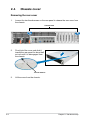
2.1 Chassis cover ............................................................................... 2-2
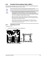
2.2 Central Processing Unit (CPU) ...................................................
2-3
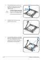
2.2.1 Installing the CPU ...........................................................
2-3
2.2.2 Installing the CPU heatsink .............................................
2-8
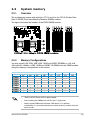
2.3 System memory ...........................................................................
2-9
2.3.1 Overview .........................................................................
2-9
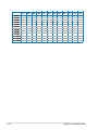
2.3.2 Memory Congurations ...................................................
2-9
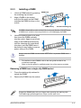
2.3.3 Installing a DIMM ...........................................................
2-11
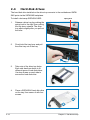
2.4 Hard disk drives .........................................................................
2-12
2.5 Expansion slots ..........................................................................
2-14
2.5.1 Installing an expansion card .........................................
2-14
2.5.2 Conguring an expansion card .....................................
2-15
2.5.3 PCI Express x16 slot (x16 link) .....................................
2-16
2.5.4 PCI Express x8 slot (x8 link) .........................................
2-16
2.6 Cable connections .....................................................................
2-17
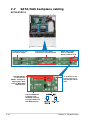
2.7 SATA/SAS backplane cabling ...................................................
2-18
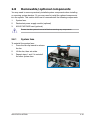
2.8 Removable/optional components .............................................
2-19
2.8.1 System fans ..................................................................
2-19
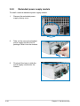
2.8.2 Redundant power supply module .................................
2-20
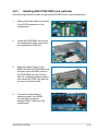
2.8.3 Installing ASUS PIKE RAID card (optional) ..................
2-21

iv
Contents
Chapter 3: Installation options
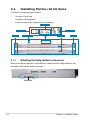
3.1 Installing friction rail kit items .................................................... 3-2
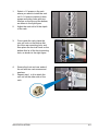
3.1.1 Attaching the xing latches to the server ........................
3-2
3.1.2 Mounting the server to the rack ......................................
3-5
Chapter 4: Motherboard Info
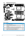
4.1 Motherboard layout ...................................................................... 4-2
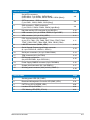
4.2 Jumpers ........................................................................................
4-4
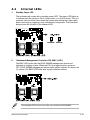
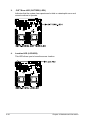
4.3 Internal connectors ......................................................................
4-8
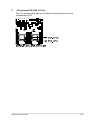
4.4 Internal LEDs ..............................................................................
4-19
Chapter 5: BIOS setup
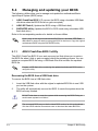
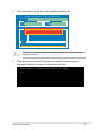
5.1 Managing and updating your BIOS ............................................ 5-2
5.1.1 ASUS CrashFree BIOS 3 utility ......................................
5-2
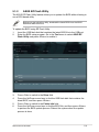
5.1.2 ASUS EZ Flash Utility .....................................................
5-3
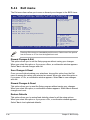
5.1.3 BUPDATER utility
............................................................ 5-4
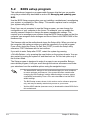
5.2 BIOS setup program ....................................................................
5-6
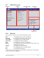
5.2.1 BIOS menu screen ..........................................................
5-7
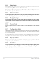
5.2.2 Menu bar .........................................................................
5-7
5.2.3 Menu items .....................................................................
5-8
5.2.4 Submenu items ...............................................................
5-8
5.2.5 Navigation keys ...............................................................
5-8
5.2.6 General help ...................................................................
5-8
5.2.7 Conguration elds .........................................................
5-8
5.2.8 Pop-up window ...............................................................
5-8
5.2.9 Scroll bar .........................................................................
5-8
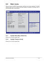
5.3 Main menu ....................................................................................
5-9
5.3.1 System Date [Day xx/xx/xxxx] .........................................
5-9
5.3.2 System Time [xx:xx:xx] ...................................................
5-9
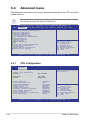
5.4 Advanced menu .........................................................................
5-10
5.4.1 CPU Conguration ........................................................
5-10
5.4.2 CPU Power Management Conguration .......................
5-12
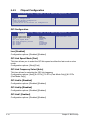
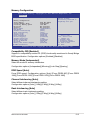
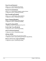
5.4.3 Chipset Conguration ...................................................
5-14
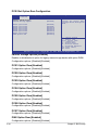
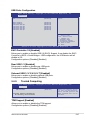
5.4.4 PCH SATA Conguration ..............................................
5-20
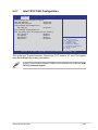
5.4.5 PCH SCU Conguration ...............................................
5-21
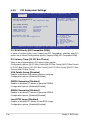
5.4.6 PCI Subsystem Settings ...............................................
5-22

v
Contents
5.4.7 Intel TXT(LT-SX) Conguration ..................................... 5-25
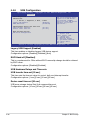
5.4.8 USB Conguration ........................................................
5-26
5.4.9 Trusted Computing ........................................................
5-27
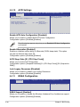
5.4.10 ACPI Settings ................................................................
5-28
5.4.11 WHEA Conguration .....................................................
5-28
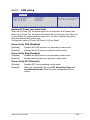
5.4.12 APM setting ...................................................................
5-29
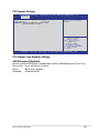
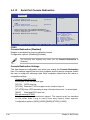
5.4.13 Serial Port Console Redirection ....................................
5-30
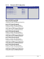
5.4.14 Onboard LAN Conguration ..........................................
5-33
5.4.15 ME Subsystem ..............................................................
5-34
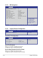
5.4.16 Legacy Devices Conguration ......................................
5-34
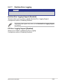
5.4.17 Runtime Error Logging ..................................................
5-35
5.5 Server Mgmt menu .....................................................................
5-36
5.5.1 System Event Log .........................................................
5-37
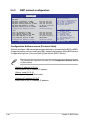
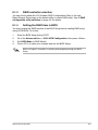
5.5.2 BMC network conguration ...........................................
5-38
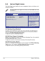
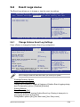
5.6 Event Logs menu .......................................................................
5-39
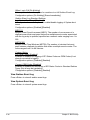
5.6.1 Change Smbios Event Log Settings .............................
5-39
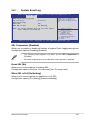
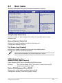
5.7 Boot menu ..................................................................................
5-41
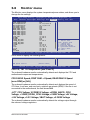
5.8 Monitor menu .............................................................................
5-43
5.9 Security menu ............................................................................
5-44
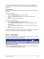
5.10 Tool menu ...................................................................................
5-45
5.11 Exit menu ....................................................................................
5-46
Chapter6: RAIDconguration
6.1 Setting up RAID ............................................................................ 6-2
6.1.1 RAID denitions ..............................................................
6-2
6.1.2 Installing hard disk drives ................................................
6-2
6.1.3 RAID controller selection ................................................
6-3
6.1.4 Setting the RAID item in BIOS ........................................
6-3
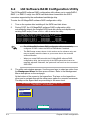
6.2 LSISoftwareRAIDCongurationUtility ....................................
6-4
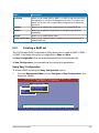
6.2.1 Creating a RAID set ........................................................
6-5
6.2.2 Adding or viewing a RAID conguration ........................
6-11
6.2.3 Initializing the virtual drives ...........................................
6-12
6.2.4 Rebuilding failed drives .................................................
6-16
6.2.5 Checking the drives for data consistency .....................
6-18
6.2.6 Deleting a RAID conguration .......................................
6-21

vi
Contents
6.2.7 Selecting the boot drive from a RAID set ...................... 6-22
6.2.8 Enabling WriteCache ....................................................
6-23
6.3 Intel
®
Rapid Storage Technology Option ROM Utility ............. 6-24
6.3.1 Creating a RAID set ......................................................
6-25
6.3.2 Creating a Recovery set ...............................................
6-26
6.3.3 Deleting a RAID set ......................................................
6-28
6.3.4 Resetting disks to Non-RAID ........................................
6-29
6.3.5 Recovery Volume Options ............................................
6-30
6.3.6 Exiting the Intel
®
Rapid Storage Technology utility ........ 6-31
6.3.7 Rebuilding the RAID .....................................................
6-31
6.3.8 Setting the Boot array in the BIOS Setup Utility ............
6-33
Chapter 7: Driver installation
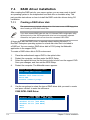
7.1 RAID driver installation ............................................................... 7-2
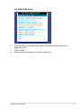
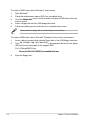
7.1.1 Creating a RAID driver disk ............................................
7-2
7.1.2 Installing the RAID controller driver ................................ 7-5
7.2 Intel
®
chipset device software installation ............................... 7-15
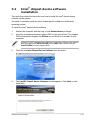
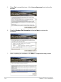
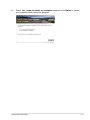
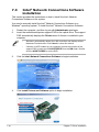
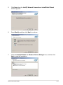
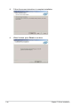
7.3 Intel
@
Network Connections Software installation.................. 7-18
7.4 VGA driver installation
............................................................... 7-21
7.5 Intel
®
C600 Series Chipset SCU SATA RAID Drivers ............... 7-24
7.6 Intel
®
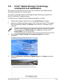
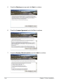
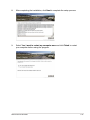
Rapid Storage Technology enterprise 3.0 installation . 7-25
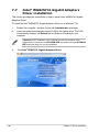
7.7 Intel
®
WG82574L Gigabit Adapters Driver installation ............ 7-28
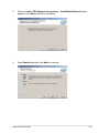
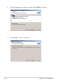
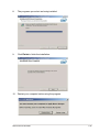
7.8 Management applications and utilitiesinstallation .................
7-32
7.8.1 Running the support DVD .............................................
7-32
7.8.2 Drivers menu .................................................................
7-32
7.8.3 Utilities menu ................................................................
7-33
7.8.4 Make disk menu ............................................................
7-33
7.8.5 Contact information .......................................................
7-33
ASUS contact information .......................................................................A-1

vii
Notices
Federal Communications Commission Statement
This device complies with Part 15 of the FCC Rules. Operation is subject to the
following two conditions:
• This device may not cause harmful interference, and
• This device must accept any interference received including interference that
may cause undesired operation.
This equipment has been tested and found to comply with the limits for a Class
B digital device, pursuant to Part 15 of the FCC Rules. These limits are designed
to provide reasonable protection against harmful interference in a residential
installation. This equipment generates, uses and can radiate radio frequency
energy and, if not installed and used in accordance with manufacturer’s instructions,
may cause harmful interference to radio communications. However, there is no
guarantee that interference will not occur in a particular installation. If this equipment
does cause harmful interference to radio or television reception, which can be
determined by turning the equipment off and on, the user is encouraged to try to
correct the interference by one or more of the following measures:
• Reorient or relocate the receiving antenna.
• Increase the separation between the equipment and receiver.
• Connect the equipment to an outlet on a circuit different from that to which the
receiver is connected.
• Consult the dealer or an experienced radio/TV technician for help.
Canadian Department of Communications Statement
This digital apparatus does not exceed the Class A limits for radio noise emissions
from digital apparatus set out in the Radio Interference Regulations of the
Canadian Department of Communications.
This Class A digital apparatus complies with Canadian ICES-003.
WARNING! The use of shielded cables for connection of the monitor to the
graphics card is required to assure compliance with FCC regulations. Changes
or modications to this unit not expressly approved by the party responsible for
compliance could void the user’s authority to operate this equipment.
REACH Information
Complying with the REACH (Registration, Evaluation, Authorization, and Restriction
of Chemicals) regulatory framework, we publish the chemical substances in our
products at ASUS REACH website at http://green.asus.com/english/REACH.htm.

viii
Safety information
Electrical Safety
• Before installing or removing signal cables, ensure that the power cables for
the system unit and all attached devices are unplugged.
• To prevent electrical shock hazard, disconnect the power cable from the
electrical outlet before relocating the system.
• When adding or removing any additional devices to or from the system, ensure
that the power cables for the devices are unplugged before the signal cables
are connected. If possible, disconnect all power cables from the existing
system before you add a device.
• If the power supply is broken, do not try to x it by yourself. Contact a qualied
service technician or your dealer.
Operation Safety
• Any mechanical operation on this server must be conducted by certied or
experienced engineers.
• Before operating the server, carefully read all the manuals included with the
server package.
• Before using the server, ensure all cables are correctly connected and the
power cables are not damaged. If any damage is detected, contact your dealer
as soon as possible.
• To avoid short circuits, keep paper clips, screws, and staples away from
connectors, slots, sockets and circuitry.
• Avoid dust, humidity, and temperature extremes. Place the server on a stable
surface.
Lithium-Ion Battery Warning
CAUTION! Danger of explosion if battery is incorrectly replaced. Replace
only with the same or equivalent type recommended by the manufacturer.
Dispose of used batteries according to the manufacturer’s instructions.
Heavy System
CAUTION! This server system is heavy. Ask for assistance when moving or
carrying the system.
This product is equipped with a three-wire power cable and plug for the user’s
safety. Use the power cable with a properly grounded electrical outlet to avoid
electrical shock.
CD-ROM Drive Safety Warning
CLASS 1 LASER PRODUCT

ix
About this guide
Audience
This user guide is intended for system integrators, and experienced users with at
least basic knowledge of conguring a server.
Contents
This guide contains the following parts:
1. Chapter 1: Product Introduction
This chapter describes the general features of the server, including sections
on front panel and rear panel specications.
2. Chapter 2: Hardware setup
This chapter lists the hardware setup procedures that you have to perform
when installing or removing system components.
3. Chapter 3: Installation options
This chapter describes how to install optional components into the barebone
server.
4. Chapter 4: Motherboard information
This chapter gives information about the motherboard that comes with the
server. This chapter includes the motherboard layout, jumper settings, and
connector locations.
5. Chapter 5: BIOS setup
This chapter tells how to change system settings through the BIOS Setup
menus and describes the BIOS parameters.
6. Chapter6:RAIDconguration
This chapter tells how to change system settings through the BIOS Setup
menus. Detailed descriptions of the BIOS parameters are also provided.
7 Chapter 7: Driver installation
This chapter provides instructions for installing the necessary drivers for
different system components.
DO NOT throw the motherboard in municipal waste. This product has been designed
to enable proper reuse of parts and recycling. This symbol of the crossed out wheeled
bin indicates that the product (electrical and electronic equipment) should not be
placed in municipal waste. Check local regulations for disposal of electronic products.
DO NOT throw the mercury-containing button cell battery in municipal waste.
This symbol of the crossed out wheeled bin indicates that the battery should not
be placed in municipal waste.

x
References
Refer to the following sources for additional information, and for product and
software updates.
1. ASUS Server Web-based Management (ASWM) user guide
This manual tells how to set up and use the proprietary ASUS server
management utility.
2. ASUS websites
The ASUS websites worldwide provide updated information for all ASUS
hardware and software products. Refer to the ASUS contact information.
Conventions
To ensure that you perform certain tasks properly, take note of the following
symbols used throughout this manual.
Typography
Bold text
Indicates a menu or an item to select.
Italics
Used to emphasize a word or a phrase.
<Key> Keys enclosed in the less-than and greater-than
sign means that you must press the enclosed key.
Example: <Enter> means that you must press
the Enter or Return key.
<Key1+Key2+Key3> If you must press two or more keys simultaneously,
the key names are linked with a plus sign (+).
Example: <Ctrl+Alt+Del>
Command
Means that you must type the command
exactly as shown, then supply the required
item or value enclosed in brackets.
Example: At the DOS prompt, type the
command line:
format A:/S
DANGER/WARNING: Information to prevent injury to yourself when
trying to complete a task.
CAUTION: Information to prevent damage to the components when
trying to complete a task.
NOTE: Tips and additional information to help you complete a task.
IMPORTANT: Instructions that you MUST follow to complete a task.

1-
This chapter describes the general
features of the chassis kit. It includes
sections on front panel and rear panel
specications.
Chapter 1
Product introduction

Chapter 1: Product introduction1-2
*ASUS System Web-based Management
If any of the above items is damaged or missing, contact your retailer.
1.1 System package contents
Check your system package for the following items.
Model Name RS720-X7/RS8
Chassis ASUS R20D 2U Rackmount Chassis
Motherboard ASUS Z9PR-D12/4L Server Board
Component 1 x 770W Redundant Power Supply
1 x SATA HDD Backplane (BP8LX-R21B)
8 x hot-swap HDD trays
1 x Front I/O Shield
1 x Front USB Board
4 x System Fans (80 x 38mm)
1 x Redundant Power Supply Distribution Board (PDB-R20A)
Accessories 1 x RS720-X7/RS8 User’s Guide
1 x ASWM Enterprise User’s Guide
1 x RS720-X7/RS8 Support DVD
1 x Bag of Screws
1 x ASWM Enterprise DVD
1 x ASMB6 Series DVD
1 x ASMB6 User’s Guide
2 x AC Power Cable
1 x Friction Rail Kit
Optional Items Second 770W Redundant Power Supply Module
Slim-type Optical Device
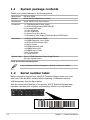
1.2 Serial number label
Before requesting support from the ASUS Technical Support team, you must
take note of the product’s serial number containing 14 characters such as
xxS0xxxxxxxxxx. See the gure below.
With the correct serial number of the product, ASUS Technical Support team
members can then offer a quicker and satisfying solution to your problems.
xxS0xxxxxxxxxx
RS720-X7/RS8

ASUS RS720-X7/RS8 1-3
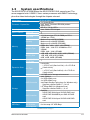
1.3 Systemspecications
The ASUS RS720-X7/RS8 feature the ASUS Z9PR-D12/4L server board. The
server supports Intel
®
LGA2011 Xeon
®
series processors with EM64T technology,
plus other latest technologies through the chipsets onboard.
(continued on the next page)
Model Name RS720-X7/RS8
Processor / System Bus
2 x Socket-R 2011
Intel
®
Xeon
®
Processor E5-2600 product
family(115W)
QPI 6.4 / 7.2 / 8.0 GT/s
Core Logic Intel
®
C602-A PCH chipset
ASUS Features
Smart Fan √
ASWM Enterprise √
Memory
Total Slots
12 (4-channel per CPU, 8 DIMM per CPU1,
4 DIMM per CPU2)
Capacity
Maximum up to 96GB (UDIMM)
Maximum up to 384GB (RDIMM)
Maximum up to 384GB (LRDIMM)
Memory Type
DDR3 800 / 1066 / 1333 / 1600 RDIMM
DDR3 1066 / 1333 ECC UDIMM/Non-ECC
UDIMM
DDR3 1066 / 1333 LR-DIMM
Memory Size
1GB, 2GB, 4GB, 8GB, 16GB, 32GB (RDIMM)
1GB, 2GB, 4GB, 8GB (UDIMM)
8GB, 16GB, 32GB (LRDIMM)
Expansion Slots
Total PCI/PCI-X/
PCI-E Slots
7
Slot Type
Low-prole:
- 1 x PCI-E x16 (Gen3 x16 link) + 5 x PCI-E x8
(Gen3 x8 link)
or
- 1 x PCI-E x16 (Gen3 x8 link) + 6 x PCI-E x8
(Gen3 x8 link)
Additional Slot 1 1 x PIKE slot for storage enhancement
Storage
SATA Controller
Intel
®
C602-A:
2 x SATA 6Gb/s ports
4 x SATA 3Gb/s ports
Intel Rapid Storage Technology (for Windows only)
- Supports software RAID 0, 1, 10 & 5
LSI
®
Mega RAID (for Windows/Linux)
- Supports software RAID 0, 1, & 10
SAS Controller
Optional:
- ASUS PIKE 2008 8-port SAS 6G RAID card
- ASUS PIKE 2008/IMR 8-port SAS 6G RAID
card
- ASUS PIKE 2108 8-port SAS 6G H/W RAID
card
HDD Bays
I = internal
A or S will be
hot-swappable
8 x Hot-swap 3.5” HDD Bays

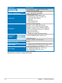
Chapter 1: Product introduction1-4
*Specicationsaresubjecttochangewithoutnotice.
Model Name RS720-X7/RS8
Networking LAN
4 x Intel 82574L + 1 x Mgmt LAN per Node
Graphic VGA
Aspeed AST2300 16MB
Auxiliary Storage Device Bay
(Floppy / Optical Device)
1 x Slim-type optical Device Bay
Options: No Device / DVD-RW
Onboard I/O
2 x Internal Serial Port
5 x RJ-45 ports (1 for ASMB6-iKVM)
4 x USB 2.0 ports (Front x 2, Rear x 2)
1 x Internal A Type USB Port
1 x VGA port
1 x PS/2 keyboard port
1 x PS/2 mouse port
OS Support
Windows
®
Server 2008 R2
Windows
®
Server 2008 R2 Enterprise
Windows
®
Server 2008 Enterprise 32/64-bit
RedHat
®
Enterprise Linux AS5.6/6.0 32/64-bit
SuSE
®
Linux Enterprise Server 11.2 32/64-bit
CentOS 5.6 32/64-bit
VMWare ESX4.1/ESXi4.1
(Subject to change without any notice)
Management
Solution
Out of Band
Remote
Hardware
Onboard ASMB6-iKVM for KVM-over-IP
Software
ASWM Enterprise
Dimension (HH x WW x DD)
615mm x 444mm x 87.0mm (2U)
Net Weight Kg (CPU, DRAM &
HDD not inclu ded)
22 Kg
Power Supply
1+1 Redundant 770W 80PLUS Gold Power Supply
(following different conguration by region)
Environment
Operating temperature: 10°C–35°C
Non operating temperature: -40°C–70°C
Non operating humidity: 20%–90%
(Non-condensing)

ASUS RS720-X7/RS8 1-5
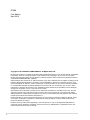
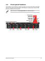
1.4 Front panel features
The barebone server displays a simple yet stylish front panel with easily accessible
features. The power and reset buttons, LED indicators, optical drive, and two USB
ports are located on the front panel.
Refer to section 1.7.1 Front panel LEDs for the LED descriptions.
Slim-type optical drive(optional)
USB ports
Power
button
Power
LED
LAN2/4 LED
HDD Access LED
LAN1/3 LED
Message LED
Location switch
Reset button
Location LED
HDD 1 HDD 5 HDD 2 HDD 6 HDD 3 HDD 7 HDD 4 HDD 8

Chapter 1: Product introduction1-6
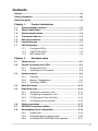
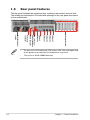
• The ports for the PS/2 keyboard, PS/2 mouse, USB, VGA, and Gigabit LAN
do not appear on the rear panel if motherboard is not present.
• *The port is for ASUS ASMB6-iKVM only.
1.5 Rear panel features
The rear panel includes the expansion slots, system power socket, and rear fans.
The middle part includes the I/O shield with openings for the rear panel connectors
on the motherboard.
PS/2 keyboard port
USB ports
LAN port 1
VGA port
7 Expansion slots
LAN port 2
Power cord
connector
PS/2 mouse port
Redundant power
supply
DM_LAN 1 port *
LAN port 3
LAN port 4

ASUS RS720-X7/RS8 1-7
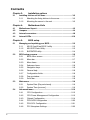
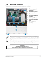
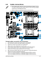
1.6 Internal features
The barebone server includes the basic components as shown.
The barebone server does not include a oppy disk drive. Connect a USB oppy
disk drive to any of the USB ports on the front or rear panel if you need to use a
oppy disk.
*WARNING
HAZARDOUS MOVING PARTS
KEEP FINGERS AND OTHER BODY PARTS AWAY
1. Power supply and
power fan
2.
ASUS Z9PR-D12/4L
server board
3. System fans
4. SATA/SAS backplane
(hidden)
5. Hot-swap HDD tray
6. Slim-type optical drive
bay
7. Front
I/O board
(hidden)
A protection lm is pre-attached to the front cover before shipping. Please
remove the protection lm before turning on the system for proper heat
dissipation.
1
2
3
5
6 7
4
3 3 3

Chapter 1: Product introduction1-8
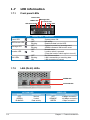
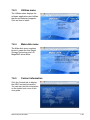
1.7 LED information
1.7.1 Front panel LEDs
1.7.2 LAN (RJ-45) LEDs
ACT/LINK LED SPEED LED
Status Description Status Description
OFF No link OFF 10 Mbps connection
GREEN Linked ORANGE 100 Mbps connection
BLINKING Data activity GREEN 1 Gbps connection
SPEED LED
ACT/LINK LED
LED Icon Display status Description
Power LED ON System power ON
HDD Access LED
OFF
Blinking
No activity
Read/write data into the HDD
Message LED
OFF
Blinking
System is normal; no incoming event
ASWM indicates a HW monitor event
Location LED
OFF
ON
Normal status
Location switch is pressed
(Press the location switch again to turn off)
LAN LEDs
OFF
Blinking
ON
No LAN connection
LAN is transmitting or receiving data
LAN connection is present
Message LED
LAN2/4 LED
HDD Access LED
LAN1/3 LED
Power LED
Location LED

ASUS RS720-X7/RS8 1-9
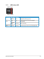
1.7.3 HDD status LED
SATAII/SAS HDD LED Description
HDD Status
LED
GREEN ON SATAII/SAS HDD power ON
RED ON
HDD has failed and should be swapped
immediately
GREEN/
RED
Blinking RAID rebuilding
HDD Activity
LED
GREEN Blinking Read/write data from/into the SATAII/SAS HDD
HDD status LED
HDD Activity LED

Chapter 1: Product introduction1-10
Page is loading ...
Page is loading ...
Page is loading ...
Page is loading ...
Page is loading ...
Page is loading ...
Page is loading ...
Page is loading ...
Page is loading ...
Page is loading ...
Page is loading ...
Page is loading ...
Page is loading ...
Page is loading ...
Page is loading ...
Page is loading ...
Page is loading ...
Page is loading ...
Page is loading ...
Page is loading ...
Page is loading ...
Page is loading ...
Page is loading ...
Page is loading ...
Page is loading ...
Page is loading ...
Page is loading ...
Page is loading ...
Page is loading ...
Page is loading ...
Page is loading ...
Page is loading ...
Page is loading ...
Page is loading ...
Page is loading ...
Page is loading ...
Page is loading ...
Page is loading ...
Page is loading ...
Page is loading ...
Page is loading ...
Page is loading ...
Page is loading ...
Page is loading ...
Page is loading ...
Page is loading ...
Page is loading ...
Page is loading ...
Page is loading ...
Page is loading ...
Page is loading ...
Page is loading ...
Page is loading ...
Page is loading ...
Page is loading ...
Page is loading ...
Page is loading ...
Page is loading ...
Page is loading ...
Page is loading ...
Page is loading ...
Page is loading ...
Page is loading ...
Page is loading ...
Page is loading ...
Page is loading ...
Page is loading ...
Page is loading ...
Page is loading ...
Page is loading ...
Page is loading ...
Page is loading ...
Page is loading ...
Page is loading ...
Page is loading ...
Page is loading ...
Page is loading ...
Page is loading ...
Page is loading ...
Page is loading ...
Page is loading ...
Page is loading ...
Page is loading ...
Page is loading ...
Page is loading ...
Page is loading ...
Page is loading ...
Page is loading ...
Page is loading ...
Page is loading ...
Page is loading ...
Page is loading ...
Page is loading ...
Page is loading ...
Page is loading ...
Page is loading ...
Page is loading ...
Page is loading ...
Page is loading ...
Page is loading ...
Page is loading ...
Page is loading ...
Page is loading ...
Page is loading ...
Page is loading ...
Page is loading ...
Page is loading ...
Page is loading ...
Page is loading ...
Page is loading ...
Page is loading ...
Page is loading ...
Page is loading ...
Page is loading ...
Page is loading ...
Page is loading ...
Page is loading ...
Page is loading ...
Page is loading ...
Page is loading ...
Page is loading ...
Page is loading ...
Page is loading ...
Page is loading ...
Page is loading ...
Page is loading ...
Page is loading ...
Page is loading ...
Page is loading ...
Page is loading ...
Page is loading ...
Page is loading ...
Page is loading ...
Page is loading ...
Page is loading ...
Page is loading ...
Page is loading ...
Page is loading ...
Page is loading ...
Page is loading ...
Page is loading ...
Page is loading ...
Page is loading ...
Page is loading ...
Page is loading ...
Page is loading ...
Page is loading ...
Page is loading ...
Page is loading ...
Page is loading ...
Page is loading ...
Page is loading ...
Page is loading ...
Page is loading ...
Page is loading ...
Page is loading ...
Page is loading ...
Page is loading ...
Page is loading ...
Page is loading ...
Page is loading ...
Page is loading ...
Page is loading ...
Page is loading ...
Page is loading ...
Page is loading ...
Page is loading ...
Page is loading ...
-
 1
1
-
 2
2
-
 3
3
-
 4
4
-
 5
5
-
 6
6
-
 7
7
-
 8
8
-
 9
9
-
 10
10
-
 11
11
-
 12
12
-
 13
13
-
 14
14
-
 15
15
-
 16
16
-
 17
17
-
 18
18
-
 19
19
-
 20
20
-
 21
21
-
 22
22
-
 23
23
-
 24
24
-
 25
25
-
 26
26
-
 27
27
-
 28
28
-
 29
29
-
 30
30
-
 31
31
-
 32
32
-
 33
33
-
 34
34
-
 35
35
-
 36
36
-
 37
37
-
 38
38
-
 39
39
-
 40
40
-
 41
41
-
 42
42
-
 43
43
-
 44
44
-
 45
45
-
 46
46
-
 47
47
-
 48
48
-
 49
49
-
 50
50
-
 51
51
-
 52
52
-
 53
53
-
 54
54
-
 55
55
-
 56
56
-
 57
57
-
 58
58
-
 59
59
-
 60
60
-
 61
61
-
 62
62
-
 63
63
-
 64
64
-
 65
65
-
 66
66
-
 67
67
-
 68
68
-
 69
69
-
 70
70
-
 71
71
-
 72
72
-
 73
73
-
 74
74
-
 75
75
-
 76
76
-
 77
77
-
 78
78
-
 79
79
-
 80
80
-
 81
81
-
 82
82
-
 83
83
-
 84
84
-
 85
85
-
 86
86
-
 87
87
-
 88
88
-
 89
89
-
 90
90
-
 91
91
-
 92
92
-
 93
93
-
 94
94
-
 95
95
-
 96
96
-
 97
97
-
 98
98
-
 99
99
-
 100
100
-
 101
101
-
 102
102
-
 103
103
-
 104
104
-
 105
105
-
 106
106
-
 107
107
-
 108
108
-
 109
109
-
 110
110
-
 111
111
-
 112
112
-
 113
113
-
 114
114
-
 115
115
-
 116
116
-
 117
117
-
 118
118
-
 119
119
-
 120
120
-
 121
121
-
 122
122
-
 123
123
-
 124
124
-
 125
125
-
 126
126
-
 127
127
-
 128
128
-
 129
129
-
 130
130
-
 131
131
-
 132
132
-
 133
133
-
 134
134
-
 135
135
-
 136
136
-
 137
137
-
 138
138
-
 139
139
-
 140
140
-
 141
141
-
 142
142
-
 143
143
-
 144
144
-
 145
145
-
 146
146
-
 147
147
-
 148
148
-
 149
149
-
 150
150
-
 151
151
-
 152
152
-
 153
153
-
 154
154
-
 155
155
-
 156
156
-
 157
157
-
 158
158
-
 159
159
-
 160
160
-
 161
161
-
 162
162
-
 163
163
-
 164
164
-
 165
165
-
 166
166
-
 167
167
-
 168
168
-
 169
169
-
 170
170
-
 171
171
-
 172
172
-
 173
173
-
 174
174
-
 175
175
-
 176
176
-
 177
177
-
 178
178
-
 179
179
-
 180
180
-
 181
181
-
 182
182
-
 183
183
-
 184
184
-
 185
185
-
 186
186
-
 187
187
-
 188
188


Asus PIKE 2008 IMR User manual
- Category
- Disk arrays
- Type
- User manual
- This manual is also suitable for
Ask a question and I''ll find the answer in the document
Finding information in a document is now easier with AI
Related papers
-
Asus RS720-X7/RS8 Owner's manual
-
-
Asus RS920A-E6/RS8 T6861 User manual
-
Asus RS720-E7/RS12 User manual
-
-
-
Asus ROG MAXIMUS XI GENE Specification
-
-
-
Other documents
-
 Kaser YOFUN010-2 User manual
-
ASROCK C216 WS Quick start guide
-
-
HP DL280 User guide
-
Toshiba HDTD205SMEA User guide
-
Zebra NX-9600 Owner's manual
-
 IO CREST SI-MPE40095 User guide
-
Emprex D350PE Quick start guide
-
-
Acer Altos T110 F4 User manual

