Page is loading ...

RTX220 QR - Manual
RTX
™
Secure IR User Manual
A7-680-0001 Revision: 1.2
• Hardware-based AES 256-bit Encryption – Offers affordable military-grade AES 256-bit data protection
thatencryptstheentireharddrive–includingbootsector,OS,temp,andswaples.
• Meets Industry Standards – All CRU Secure 256-bit product architecture and encryption engine
designsmeetFIPS140-2,level3percerticationnumber1471,andallCRUAES256-bitsecuritychips
are NIST & CSE validated (FIPS PUB 197).
• Easy-to-Use Security – One physical Security Key is used for all bays and the Security Key can be
stored separately from the unit to make the RTX Secure less vulnerable to attack if the unit is lost or
stolen. No PINs or passwords are needed.
• TrayFree
™
Trayless Technology for RTX – TrayFree bays make installing drives a breeze. It really is as
easy as opening the door, sliding the drive in, and closing the door. No screws, no trays, it just works.
Models Covered:
RTX Secure 610-IR
RTX Secure 810-IR
RTX
TM

RTX220 QR - Manual
Page 2
Table of Contents
1. Default GUI Login Information
3
2. Pre-Installation Steps
2.1 Accessories 3
2.2 Identifying Parts of the RTX Secure 3
2.3 Warnings and Notices 3
2.4 Terminology 4
3. Introduction to RAID
3.1 Summary of RAID Levels 4
4. Introduction to iSCSI
4.1 What is iSCSI? 5
4.2WhatistheBenetofiSCSI? 5
4.3 What is iSCSI Not? 5
5. Installation Steps
2.1 Hard Drive Installation 5
2.2 Setting the Encryption Mode 6
2.3 Operating the RTX Secure 6
6. Other Conguration Options
6.1MissingSecurityKeyNotication 6
6.2 Hot Swapping Encrypted Hard Drives 7
6.3 Recovering From a Failed RAID 7
7. Network Conguration
7.1 Connecting the RTX Secure to Your
Network or Computer
7
7.2UsingtheLCDtoCongureGUIAccess 7
7.2.1 Navigating the LCD Menu 7
7.2.2 LCD Functions 7
7.2.3 RTX Secure LCD Menu Diagram 7
7.2.4 Instructions for Different
Network Connection Types
8
8. Using the GUI
8.1GUIIndicators 9
8.2GUIMenuStructure 10
8.3 Manually Creating a RAID Set 10
8.3.1CreatingaRAIDGroup 10
8.3.2 Creating a Virtual Disk 11
8.3.3 Attaching a Logical Unit 12
8.4 Quick Installation 12
8.5SystemConguration 12
8.5.1 System Settings 12
8.5.2 IP Address 13
8.5.3 Login Settings 13
8.5SystemConguration(cont.)
8.5.4 Mail Settings 14
8.5.5NoticationSettings 14
8.6iSCSIConguration 15
8.6.1 Entity Property 15
8.6.2 NIC 15
8.6.3 Node 15
8.6.4 Session 16
8.6.5 CHAP Account 16
8.7VolumeConguration 16
8.7.1 Volume Creation Wizard 17
8.7.2 Physical Disk 17
8.7.3RAIDGroup 18
8.7.4 Virtual Disk 19
8.7.5 Logical Unit 20
8.8 Enclosure Management 20
8.8.1SESConguration 20
8.8.2 Hardware Monitor 20
8.8.3 S. M. A. R. T. 21
8.9 Maintenance 21
8.9.1 System Information 21
8.9.2 Upgrade 21
8.9.3 Reset to Factory Default 21
8.9.4 Import & Export 21
8.9.5 Event Log 21
8.9.6 Reboot and Shutdown 21
8.10 Online Support 21
8.11 Logout 21
9. iSCSI Initiator Software
9.1 Software Installation 22
9.2 Access the RTX Secure Using iSCSI Initiator Software 22
10. Usage with Windows and Mac Operating Systems
23
11. RAID Is Not A Backup
25
12. Encryption
25
13. Event Notications
25
14. Working With Volumes Larger Than 2 TB in Size
28
15. Frequently Asked Questions (FAQ)
29
16. Technical Specications
31

RTX220 QR - Manual
Page 3
2.3 Warnings and Notices
Please read the following before beginning installation.
General Care
• The main circuit boards of the HDD carriers are susceptible to
static electricity. Proper grounding is strongly recommended
to prevent electrical damage to the enclosure or other
connected devices, including the computer host. Avoid all
dramatic movement, tapping on the unit, and vibration.
• Avoid placing the HDD carriers close to magnetic devices,
high voltage devices, or near a heat source. This includes any
place where the product will be subject to direct sunlight. Do
NOT allow water to make contact with the carrier or receiving
frame.
• Before starting any type of hardware installation, please
ensure that all power switches have been turned off and all
power cords have been disconnected to prevent personal injury
and damage to the hardware.
1. Default GUI Login Information
The following login and password information can be used to easily log
intotheGUI(SeeSection8forinstructionsonhowtologintoanduse
theGUI).
Administrator Account
This account has read and write privileges.
Username: admin
Password: 1234
User Account
This account has read-only privileges.
Username: user
Password: 1234
2. Pre-Installation Steps
2.1 Check the Accessories with Your RTX Secure
Please contact CRU-DataPort if any items are missing or damaged.
The box should contain the following items:
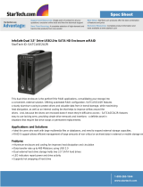
2.2 Identifying Parts
Take a moment to familiarize yourself with the parts of RTX Secure.
This will help you to better understand the remaining instructions.
Accessories Quantity
RTX Secure Unit 1
Power cord 1
Ethernet Cable 2
Security Keys 3
Lanyards for Security Keys 3
Security Key ID Tag 3
Security Key Labels 6
Packet of Keys 1
*Only packaged with SKUs that include hard drives
*RTX Secure 610-IR
model shown here.
Number of bays
available will be
different depending on
thespecicmodel.
Front of the RTX Secure*
Back of the RTX Secure
Key Lock
Drive Bay
Security Key Port
Encryption Status
LED Array
Common/Unique
Switch
Encryption Switch
Cooling Fan
Cooling Fan
CongGUIPort
iSCSI Ethernet Ports
Power Switch
Power
Supply
LCD Display
Up Button
Down Button
Escape Button
Enter Button
Power LED
Alarm LEDAccess LED
Drive Power and
Activity LEDs

RTX220 QR - Manual
Page 4
• To avoid overheating, the RTX Secure should be operated in a
well-ventilatedareaandinsuchawaythatsufcientairowis
maintained across the controller chips.
• Remove the drives before transporting the RTX Secure to
prevent damage to the drive interfaces.
RAID
• Use only hard drives that are in perfect condition. Avoid using
drives that have ever developed bad sectors during previous
usage. This could lead to possible device failure or loss of data.
• The RTX Secure supports SATA hard drives of various
specicationsanddifferentcapacities.However,we
recommend using drives of the same brand and type for
optimal performance. If drives of different capacities are used
in a RAID, the capacity of the smallest drive will determine
how much of each drive is used. The additional capacity on the
larger drives will not be used by the RAID.
• RAID level 0 will allow you to use the full combined capacity of
the drives, and offers the best data transfer speeds. However,
RAID 0 offers no protection for the data. If one drive fails in a
RAID 0, the data on all of the drives is irretrievably lost. Before
creating a RAID, investigate the various RAID types and choose
the one that is best for your needs.
• Always back up data before switching RAID types. Switching
RAID types will destroy current data. You must reformat
your drives afterwards.
Encryption
• Though the Security Key port is mechanically identical to the
standard Mini-USB port, inserting Security Keys into any other
Mini-USB port will damage the keys and render them useless.
Please only use Security Keys in RTX Secure products.
Likewise, inserting a Mini-USB cable or other device into the
RTX Secure Security Key port on the carrier can cause internal
damage and potentially lead to loss of data.
• Any time power is cycled on the RTX Secure, the Security Key
should be installed prior to recycling the power in order to
access the data on the drive.
2.4 Terminology
RAID A redundant array of independent hard disks. There are
different RAID levels with different degrees of data
protection, data availability, and performance.
JBOD All disks act as independent drives. JBOD needs at least
one hard drive.
Physical Disk (PD) BelongstothememberdiskofonespecicRAIDgroup.
RAIDGroup(RG) Acollectionofremovablemedia.OneRGconsistsofaset
of VDs and owns one RAID level attribute.
Virtual Disk (VD) EachRGcanbedividedintoseveralVDs.TheVDsfrom
oneRGhavethesameRAIDlevel,butmayhavedifferent
volume capacity.
Logical Unit Number
(LUN)
AuniqueidentierforaSCSIdevicewhichenablescom-
puters to differentiate among separate SCSI devices.
GUI GraphicalUserInterface.
RAID cell ThenumberofsubgroupsofPDsinanRG.
Dedicated Spare
(DS)
AsparediskdedicatedtoonespecicRGandisused
whenanotherdiskintheRGfails.
GlobalSpare(GS) AsparediskthatissharedamongallRGsandisused
whenanotherdiskinanRGfails.
World Wide Name
(WWN)
AuniqueidentierthatidentiesaparticularPD.
Challenge Hand-
shake Authentication
Protocol (CHAP)
An optional security mechanism to control access to the
RTX Secure through its iSCSI data ports.
Internet
Storage Name
Service (iSNS)
This protocol allows automated discovery, management,
andcongurationofiSCSIdevicesonaTCP/IPnetwork.
3. Introduction to RAID
A RAID (Redundant Array of Independent Disks) is an array of multiple
hard drives that are combined in a way that provides faster performance
and/or data safety. Your RTX unit is capable of creating and managing
several different varieties of RAID. You may choose your preferred RAID
level based on factors such as disk capacity, desired data safety, and
desired performance.
3.1 Summary of RAID Levels
The RTX Secure supports RAID Levels 0, 1, 3, 5, 6, 0+1, 10, 30, 50, 60,
& JBOD. RAID Level 5 is most commonly used by those seeking an
optimal balance of speed and data safety.
RAID
Level
Description
Min.
Drives
Data
Redundancy
Data
Transfer
Rate
0 Also known as striping. Data dis-
tributed across multiple drives in
the array. There is no data protec-
tion.
2 No data
protection
Very high
1 Also known as mirroring. All data
replicated on two separate disks.
This is a high availability solution,
but due to the 100% duplication,
only half the total disk capacity is
available for data storage.
2 1 drive Reads
higher
than a
single
disk;
Writes
similar to
a single
disk

RTX220 QR - Manual
Page 5
RAID
Level
Description
Min.
Drives
Data
Redundancy
Data
Transfer
Rate
3 Also known as Bit-Interleaved Par-
ity. Data and parity information is
subdivided and distributed across
all disks. Parity must be equal to
the smallest disk capacity in the
array. Parity information normally
stored on a dedicated parity disk.
3 1 drive Reads
are
similar to
RAID 0
5 Also known as Block-Interleaved
Distributed Parity. Data and par-
ity information is subdivided and
distributed across all disks. Can
withstand the failure of one drive.
The total capacity of all but one
of the drives is available for data
storage.
3 1 drive Reads
are
similar to
RAID 0
6 Two parity bits are used to create
double redundancy. Can withstand
the failure of two drives. The to-
tal capacity of all but two of the
drives is available for data stor-
age.
4 2 drives Slightly
less than
RAID 5
0+1 Also known as a mirror of striped
drives. Data and parity informa-
tion is subdivided and distributed
across all disks. Parity must be
equal to the smallest disk capac-
ity in the array. Parity information
normally stored on a dedicated
parity disk.
4 1 drives* Transfer
rates are
similar to
RAID 0
10 Also known as a stripe of mirrors.
Data is striped across two sepa-
rate disks and mirrored to another
disk pair.
4 1 drives* Transfer
rates are
similar to
RAID 0
30 Also known as a Striping Dedi-
cated Parity Array. RAID 30 breaks
up data into smaller blocks, and
then stripes the blocks of data to
each RAID 3 RAID set.
6 2 drives** Transfer
rates are
similar to
RAID 0
50 RAID 50 combines the straight
block-level striping of RAID 0 with
the distributed parity of RAID 5
6 2 drives** Transfer
rates are
similar to
RAID 0
60 RAID 60 combines the straight
block-level striping of RAID 0 with
the distributed double parity of
RAID 6
8 4 drives*** Transfer
rates are
similar to
RAID 0
JBOD Just A Bunch of Disks. This is not
an actual RAID level because each
disk is treated as its own entity.
1 No data
protection
Very high
* One drive from each the RAID 0 and RAID 1 sets can fail without loss of data. If both
drives in either the RAID 0 or RAID 1 set fail, then the entire RAID will fail.
** One drive from each of the striped RAID sets could fail without loss of data. If two
drives in the same striped RAID set fail, then the entire RAID will fail.
*** Two disks from each of the RAID 6 sets could fail without loss of data. If three disks
in the same striped RAID 6 set fail, then the entire RAID will fail.
4. Introduction to iSCSI
4.1 What is iSCSI?
iSCSI is a technology that allows a data storage device to be
accessed over a TCP/IP network using SCSI protocols. When your
computer’s OS receives a request for data access, it generates a SCSI
command and then sends an IP packet across a network or direct
Ethernet connection. A software utility known as an iSCSI initiator is
used to generate the SCSI commands. Such a utility must be installed
on the computer before it can access an iSCSI storage device (See
Section 9 for installation instructions).
4.2 What is the Benet of iSCSI?
An iSCSI storage device can be placed anywhere throughout a
network, so the device can reside at a great distance from the
computer which accesses it. It is also a very fast connection when
used on a gigabit network, achieving speeds of 100 megabytes (MB)/
sec or more. The connection it uses (RJ45—standard Ethernet port)
is commonly found on desktop and laptop computers, so there is no
need to purchase potentially expensive host bus adapters to provide
a connection.
4.3 What is iSCSI Not?
iSCSI storage devices are not Network Attached Storage (NAS)
devices. They have no built-in server capabilities and therefore
cannot be accessed by more than one computer at a time. Multiple
computerscanonlyaccessthedataiftheiSCSIdeviceisrst
attached to a single computer which is then set up as a server.
5 Installation Steps
5.1 Hard Drive Installation
a. Pull the ejection
handle on the
TrayFree bay to
open the bay
door.
b. Insert a bare
SATA hard drive
into the bay.
Make sure it is
label-sideupwiththeSATAconnectiononthedriveinsertedrst.
c. Shut the bay door.
d. You can optionally secure each bay door by inserting an RTX Key
into its key lock and turning it 90 degrees clockwise. Locking the
bay doors is not necessary to operate the RTX Secure.
Sticker Card
Use the stickers on the provided sticker card to label each drive if you
plan to use Unique Encrypted Mode (see Section 5.2). This will prevent
the drives from getting mixed up when they are removed from the bays.

RTX220 QR - Manual
Page 6
5.2 Setting the Encryption Mode
The RTX Secure has three modes that determine how it handles
Security Keys. The status of the mode is determined at power up.
After the unit has been successfully mounted by the system, the
Security Key may be removed and stored in a safe location. Changing
the position of the switches on the bottom of the RTX after the unit
has successfully been mounted will also not change the mode used
at power up.
Unique Encrypted Mode
This is the most secure mode of operation. A Security Key is required
to access data, and each bay is loaded with its own unique 256-bit
security value from the Security Key. These security values are all
stored in one Security Key. Flip the left switch on the bottom panel
down to “Unique” and the right switch down to “Encrypted.”
Common Encrypted Mode
This mode allows hard drives to be located in different bays within
the unit after the array is formatted. A Security Key is required to
access data. Each bay uses the same security value from the Security
Key. Flip the left switch on the bottom panel up to “Common” and
the right switch down to “Encrypted.” The Common Key LED will
illuminate.
Bypass Mode
A Security Key is not required to access data. This option cannot be
used with encrypted hard drives. Flip the right switch on the bottom
panel to “Bypass.” This option disables the Common/Unique switch.
The Bypass LED will illuminate and the drive bay Encryption Status
LEDs will remain off.
5.3 Operating RTX Secure
a. Connect the RTX Secure to a computer or network using the
included Ethernet cables. Plug one cable into the “CH-1” port. You
can optionally plug a second cable into the “CH-2” port if having a
redundant connection or increased performance is needed.
b. If you haven’t yet set up network access, connect another Ethernet
cableintothe“CongGUI”port.
c. Connect the RTX Secure to a power outlet with the included
power cord.
d. Install the hard drives into the RTX Secure (See Section 5.1).
e. Set the desired encryption mode (See Section 5.2).
f. Insert the Security Key into the Mini-USB Security Key Port on
the bottom of the RTX Secure if the drives being used in the RTX
Secure are encrypted or intended to be encrypted.
g. Flip the power switch on the rear of the unit to turn on the RTX
Secure.
h. When using the Unique or Common Encrypted Modes, wait for
each LED along the bottom panel of the RTX Secure to light green.
These encryption status LEDs correspond to one of the TrayFree
Bays above them with the leftmost LED representing the top bay
and the rightmost LED representing the bottom bay. When all
encryption status LEDs that correspond to a bay with a drive inside
are lit green, encryption is activated and the Security Key may be
removed and stored in a safe location.
i. ConguretheRTXSecurefornetworkaccessbyfollowingthe
appropriate setup instructions in Section 7.
j. CongureyourdriveswithatleastoneRAIDset.Followthe
appropriate setup instructions in Section 8. CRU DataPort
recommends manually creating the RAID set (Section 8.3) or using
the Volume Creation Wizard (Section 8.7.1).
k. ConguretheRTXSecureforaccessusingtheinstructionsin
Section 9 for setting up an iSCSI initiator.
Once a RAID set has been created and the user connects to the
RTX Secure through an iSCSI initiator, it will show up as a blank,
unallocated volume and you’ll need to format it in the RTX Secure
before you can use it. Note that formatting a volume or creating
a RAID set will erase all data on the volume, so be sure to
back up your data before installing the hard drives into this
enclosure and before beginning this operation. See Section 10
for instructions on how to format the volume with Mac or Windows
operating systems.
6 Other Conguration Options
6.1 Missing Security Key Notication
After the RTX Secure performs its power-on self-test and there is
noSecurityKeyinserted,thereisave-secondperiodwherethe
encryption status LEDs will blink red and orange. During this period
of time, a Security Key can still be inserted. When the RTX Secure
detects the key’s insertion, it will continue its power on sequence.
NOTE: Always ensure that the correct encryption mode is
selected before powering on the RTX Secure. Failure to do so
may result in a failed RAID alarm. But don’t worry, your data will
remain intact and will be accessible once the correct encryption
mode is set.
NOTE: When switching the encryption mode, the RAID
controller will still see a valid volume even when it shouldn’t.
You must rebuild the RAID whenever you change the encryption
mode. Failure to do so will not result in the loss of data, but will
result in the inability to see some or all established RAID sets.

RTX220 QR - Manual
Page 7
6.2 Hot Swapping Encrypted Hard Drives
Hot swapping of hard drives is supported by the RTX Secure as a
default feature. Make sure the correct Security Key is installed when
hot swapping an encrypted hard drive. If the Security Key is not
installed or an incorrect Security Key is detected, the bay will not
powerupandthebay’sEncryptionStatusLEDwillashorange.
6.3 Recovering from a Failed RAID
If one hard drive of a RAID set with data redundancy has failed
or has been unplugged or removed, then the status of the RAID
GroupwillreportthattheRAIDisdegradedandtheRTXSecurewill
automatically search for a spare disk to rebuild the RAID. The RTX
Securewillrstsearchforadedicatedsparedisk,thenaglobalspare
disk,andnally,ifneitherisfound,itwillwaitfortheusertoremove
the failed hard drive and insert a working replacement.
The Security Key must be present when any failed drives are
replaced. If the Security Key is not installed or an incorrect Security
Key is detected, the bay will not power up and the bay’s Encryption
StatusLEDwillashorange,preventingtheRAIDfromrebuilding.
7 Network Conguration
7.1 Connecting the RTX Secure to Your Network or
Computer
a. PluganEthernetcableintothe“CongGUI”portontherearofthe
RTX Secure.
b. Connect the other end of the Ethernet cable to your network.
Thisusuallymeanspluggingitintoarouterorhub.Inanofce
environment,youmayhaveanetworkjackbuiltintoyourofce
wall. If a network connection is not available, you can connect the
Ethernet cable directly to an RJ45 (Ethernet) port on your computer.
c. Connect the power cable to the rear of the RTX Secure and to a
grounded electrical outlet.
d. Turn on the RTX Secure’s power using the switch on the rear
panel.
7.2 Using the LCD to Congure the Cong GUI Port
RTXhasbothanLCDinterfaceandaGUI.TheLCDinterfacehasonly
basicfunctionalityandismainlyusedtoconguretheIPaddressof
theCongGUIport.OncetheCongGUIhasbeencongured,the
GUIcanbeusedtofullyconguretheRTXSecure.
7.2.1 Navigating the LCD menu
Use the four function keys, ▲(Up), ▼(Down), ESC (Escape) and
ENT (Enter) to manipulate the LCD interface. After pressing ENT
(Enter) key, you can use the ▲(Up) and ▼(Down) keys to select a
function. If there is an alarm or error message, the LCD will display
the related information.
7.2.2 LCD Functions
System Info DisplaysthedetailsofRAMandrmware.
Alarm Mute Turns off the alarm sound when an error occurs.
Reset/Shutdown Resets or shuts down the controller.
Quick Install To use “Quick Install” to set up a volume by three steps.
CRU-DataPort does not recommend using the Quick
Install option to set up your RTX Secure. For quick set-
up of a RAID, refer to Section 8.6.1.
Volume Wizard Smart steps to create a volume. Please refer to Section
8.6.1fordetailedoperationstepsinthewebGUI.
View IP Setting Display the current IP address, subnet mask, and
gateway.
ChangeIPCong Sets the IP address, subnet mask, and gateway. You can
choose to use DHCP server (for IP address allocation) or
manually specify the IP address.
Reset to Default Restores factory defaults:
Default Administrator Name: admin
Default Administrator Password: 1234
Default User Name: user
Default User Password: 1234
Default IP address: 192.168.0.1
Default subnet mask: 255.255.255.0
Default gateway: 192.168.0.254
7.2.3 RTX Secure LCD Menu Diagram
Use the following chart for reference when following the
instructions in Section 7.2.4 for setting up the RTX Secure
according to your network type.
1st
Menu
Screen
2nd
Menu
Screen
3rd
Menu
Screen
4th
Menu
Screen
5th
Menu
Screen
6th
Menu
Screen
CRU-
DataPort
RTX
[System
Info.]
[Firmware
Version
x.x.x]
[RAM Size
xxx MB]
[Alarm
Mute]
[ENT:OK
ESC: Back]
[Reset/
Shutdown]
[Reboot]
[ENT:OK
ESC: Back]
[Shut-
down]
[ENT:OK
ESC: Back]
NOTE: Always ensure that the correct encryption mode is
selected before powering on the RTX Secure. Failure to do so
may result in a failed RAID alarm. But don’t worry, your data will
remain intact and will be accessible once the correct encryption
mode is set.

RTX220 QR - Manual
Page 8
1st
Menu
Screen
2nd
Menu
Screen
3rd
Menu
Screen
4th
Menu
Screen
5th
Menu
Screen
6th
Menu
Screen
CRU-
DataPort
RTX
[Quick
Install]
RAID 0
RAID 1
RAID 3
RAID 5
RAID 6
RAID 0+1
xxxGB
[Apply The
Cong]
[ENT:OK
ESC: Back]
[Volume
Wizard]
[Local]
RAID 0
RAID 1
RAID 3
RAID 5
RAID 6
RAID 0+1
[Use
default
algorithm]
[Volume
Size] xxx
GB
[Apply The
Cong]
[ENT:OK
ESC: Back]
[View IP
Setting]
[IPCong]
[Static IP]
[IP Ad-
dress]
[DHCP IP]
[IP Subnet
Mask]
[255.255.
255.0]
[IPGate-
way]
[192.168.
010.254]
[Change IP
Cong]
[DHCP]
[ENT:OK
ESC: Back]
[Static IP]
[IP Ad-
dress]
Adjust IP
address
[IP Subnet
Mask]
Adjust
Submask
IP
[IPGate-
way]
Adjust
Gateway
IP
[Apply IP
Setting]
[ENT:OK
ESC: Back]
[Reset to
Default]
[ENT:OK
ESC: Back]
7.2.4 Instructions for Differing Network Connection Types
DHCP-Enabled Network
On DHCP networks, a new IP address is dynamically assigned to
RTX’sCongGUIportassoonasthenetworkdetectsit.Youcan
determine this address by checking the LCD interface on the front
of the RTX Secure. It will appear in this format: xxx.xxx.xxx.xxx.
Simply type this IP address into a web browser on your computer.
ThiswillaccesstheRTXSecure’sGUI,whichyouwilluseto
conguretheunit.
Static Network
a. Check your computer’s IP address, subnet mask, and gateway.
MacuserscanndthisinformationinSystemPreferences→
Network.
To do this in Windows, open Network and Sharing Center in the
Control Panel (Also called “View Network Status and Tasks”
under the “Network and Internet” category). On the left pane,
select “Change adapter settings”. Right-click on your network
(likely called Local Area Connection) and select Properties. On
the new window that opens, select “Internet Protocol Version 4
(TCP/IPv4)” and click the Properties button. Your computer’s IP
address, subnet mask, and gateway will be displayed.
b. On the RTX Secure’s LCD interface, press ENT and then scroll up
or down to “Change IP Setting”. Press ENT.
c. Scrollupordowntond“Static”.PressENT.
d. Change the IP address to closely match what your computer
is using. Or, if you are on a business network, have your IT
administrator assign you an IP address.
For example, if your computer’s IP address is 192.168.0.9,
you might change the RTX Secure’s IP to 192.168.0.7. On
smaller networks, each of the first three octets must
be the identical to your computer’s IP address! When
changing the IP address you’ll notice that a box flashes over
the digit to be changed. While the digit is selected, press
▲(Up) or ▼(Down) to change it. Press ENT to move to the
next digit.
e. After the IP address is set, enter the subnet mask address
exactly as it is shown on your computer’s TCP/IP settings.
f. Next, enter the gateway address exactly as it is shown on your
computer’s TCP/IP settings.
g. Conrmthesettingschange.Toconrm,press▲(Up) for “Yes”
and then press ENT again.
NOTE: Not sure what type of network you have? If the
IP address displayed on the LCD starts with 169.254, this
indicates that the network is probably not DHCP-enabled.
Use the instructions for a static network.
NOTE: The IP address you select must NOT be in use by
another device.

RTX220 QR - Manual
Page 9
h. Type the RTX Secure’s new IP address into a web browser on
yourcomputer.ThiswillaccesstheRTXSecure’sGUI,whichyou
willusetoconguretheunit.
Direct Connection to a Computer
The instructions are similar to those for a static network (see
above), except that your computer will not have an IP address
assigned if it’s not a part of a network. Since the RTX Secure and
your computer must have similar IP addresses, you will assign an
IP address to your computer based upon the default IP address of
the RTX Secure.
a. ChecktheRTXSecure’sLCDtondouttheIPaddressofthe
CongGUIcongurationport.Itwillappearinthisformat:xxx.
xxx.xxx.xxx.
b. Next, change your computer’s IP address so that all but the
last three digits match the RTX Secure’s address. For example,
if the RTX Secure’s IP address is 169.254.12.62, you might
assign your computer the number 169.254.12.63 (assuming no
other computer on the network is already using that number).
The process of changing your computer’s IP address varies
depending on its operating system.
Mac users can go to System Preferences → Network.
For modern Windows operating systems, open Network and
Sharing Center in the Control Panel (Also called “View Network
Status and Tasks” under the “Network and Internet” category).
On the left pane, select “Change adapter settings”. Right-
click on your network (likely called Local Area Connection)
and select Properties. On the new window that opens, select
“Internet Protocol Version 4 (TCP/IPv4)” and click the Properties
button. By default, your computer is probably set to receive a
new IP address automatically. Change the setting to manual
congurationandthentypeintheIPaddress.
c. Using the same process as the previous step, change the
computer’s Subnet Mask setting to match the RTX Secure’s
Subnet Mask setting.
d. Finally, use the RTX Secure’s LCD interface to change the
RTXSecure’sGatewaysetting.ItshouldmatchtheIPaddress
you assigned to your computer. When changing the gateway
addressyou’llnoticethataboxashesoverthedigittobe
changed. While the digit is selected, press ▲(Up) or ▼(Down)
to change it. Press ENT to move to the next digit. After the
gateway address is set, press ENT all the way to the end and
conrmthesettingschange.Toconrm,press▲(Up) for “yes”
and then press ENT again.
e. Launch a web browser and type the RTX Secure’s IP address
into the URL bar, as if it were a website. This will access the
RTXSecure’sGUI,whichyouwillusetoconguretheunit(See
Section 8).
Thetablesbelowshowexamplesettings.Thersttableshowsthe
type of settings that will appear by default. The next table shows
how the settings might look after you’ve made changes.
Connecting From Home to Ofce
The RTX Secure can also be used over the Internet. If you are
connectingtoanRTXSecureatyourofcefromhome,youwill
need to contact your IT administrator to set up a VPN client in
ordertologintotheofcenetwork.Onceyouhaveloggedinto
theofcenetwork,youcanaccesstheRTXSecurejustasifyou
wereactuallyatyourofce(seeinstructionsforDHCP-enabled
Network, Static Network, or Direct Connection to a Computer,
dependingonhowyourofcenetworkiscongured).
8 Using the GUI
Youwillusethewebbrowser-basedGUItosetupaRAIDandcreate
logicalvolumesonRTX.AftersettingupaccesstotheGUIandac-
cessing it through a web browser (see Section 7.2 for instructions), the
GUI’smainpageshouldload,displayingapictureofRTXwithseveral
options to the left. When you click on any option, you will be prompted
for a username and password. The default administrator username is
“admin” and the default password is “1234”.
8.1 GUI Indicators
ThetoprighthandcorneroftheGUIwindowdisplaysseveral
indicators.
Before Making Changes
RTX Secure Computer
IP Address 169.254.12.62 (Blank)
Mask 255.255.000.000 (Blank)
Gateway 000.000.000.000 (Blank)
After Making Changes
RTX Secure Computer
IP Address 169.254.12.62 169.254.12.63
Mask 255.255.000.000 255.255.000.000
Gateway 169.254.12.63 (Blank)

RTX220 QR - Manual
Page 10
RAID Light
GreenindicatesthattheRAIDisworkingproperly.Red
indicates a RAID error. If no RAID is set up, the light will
remain green.
Temperature Light
Greenindicatesnormal.Redindicatesabnormalsystem
temperature and probable overheating.
Voltage Light
Greenindicatesnormal.Redindicatesabnormalvoltage
status like a power surge or a bad power supply.
Fan Light
Greenindicatesthatthefanisworkingproperly.Red
indicates a malfunctioning fan that needs to be replaced.
8.2 GUI Menu Structure
• Quick installation
• Systemconguration
• System settings
• IP address
• Login settings
• Mail settings
• Noticationsettings
• iSCSIconguration
• Entity property
• NIC
• Node
• Session
• CHAP account
• Volumeconguration
• Volume creation wizard
• Physical disk
• RAID group
• Virtual disk
• Logical unit
• Enclosure management
• SESconguration
• Hardware monitor
• S.M.A.R.T.
• Maintenance
• System information
• Upgrade
• Reset to factory default
• Import and export
• Event log
• Reboot and shutdown
• Online support
• Product Information and Specs
• FAQ and Downloads
• Logout
8.3 Manually Creating a RAID Set
Use these sets of instructions to create a RAID set. To quickly create
a RAID 0, 1, 3, 5, 6, or 0+1 set using the Volume Creation Wizard, see
Section 8.6.1.
8.3.1 Creating a RAID Group
TomanuallycreateaRAIDset,youwillrstneedtocreateanew
RAIDGroup.
a. Click the “Create” button at the bottom of the page to open the
RAIDGroupcreationscreen.
b. EnteranameforthenewRAIDGroupinthersteld,andthen
select your desired RAID type or JBOD from the dropdown box.
CRU-DataPort recommends RAID 5 for maximum performance,
capacity, and security. For more information on RAID, see
Section 3. Click “Select PD” to select the drives that will be
addedtotheRAIDGroup.
NOTE: Drives must be marked as Free Disks before they
canbeaddedtoaRAIDGroup.TosetdrivestoFreeDisks,
see Section 8.7.2, subsection “Modifying Physical Disks”.

RTX220 QR - Manual
Page 11
c. All available Free Disks will be displayed. Check the drives that
youwishtoaddtotheRAIDGroup,thenclick“Conrm”.
d. The selected Physical Disks will now be displayed in the
RAIDGroupcreationscreen.EnableorDisableWriteCache,
Standby, Readahead, and Command Queuing based on
yourneeds.MostRAIDGroupswillbenewiththedefault
settings.Thenclick“Next”toproceedtotheconrmation
screen.
e. Ontheconrmationscreen,verifythattheRAIDleveliscorrect
and all of the disks you selected are displayed under “RAID PD
slot”,thenclick“Conrm”tocreatetheRAIDGroup.
f. TheRAIDGroupwillnowdisplayonthemainRAIDGroup
screen.TonishmanuallycreatingaRAIDset,aVirtualDisk
stillmustbecreatedandaLogicalUnitmustbeattached.Goto
the next section, “Creating a Virtual Disk”.
If you opted to create JBOD drives, skip to Section 8.3.3,
“Manually Attaching a Logical Unit” as Virtual Disks have
already been created for each JBOD drive.
8.3.2 Creating A Virtual Disk
AfteraRAIDGrouphasbeencreated,youcancreateassociated
Virtual Disks. You must create at least one Virtual Disk to access
the drives of the RTX Secure with a computer.
a. Click the “Create” button at the bottom of the page to open the
Virtual Disk creation screen.
b. You will see the screen below. Fill in the information and then
click“Conrm”.Eacheldisexplainedbelowthepicture.
Name
Enter a name for the Virtual Disk.
RG Name
ChoosetheRAIDGrouptowhichtheVirtualDiskwillbeadded
Capacity
Enter the capacity of the Virtual Disk. The default uses the
maximumcapacityoftheassociatedRAIDGroup.Ifyouwish
tocreatemultipleVirtualDisksontheselectedRAIDGroup,
you will need to reduce the capacity below the maximum so
thatthereisspaceleftontheRAIDGroupforadditionalVirtual
Disks.
Stripe Height (KB)
Determines how the RTX Secure organizes the RAID. Normally
the default option is preferred.
Block Size
Determinestheminimumlesizeforlesthatwillbestored
on the Virtual Disk. Higher block sizes can result in more
wastedspaceifmanysmalllesaresavedtothedrive,but
are necessary to take advantage of high capacity RAIDs. If
you are creating a Virtual Disk over 2TB in size for use
with MacOS 10.4.x or older, or for use with Windows
XP, you must increase the block size to 4096KB to take
advantage of the full capacity of the Virtual Disk. For
more information, see Section 14.

RTX220 QR - Manual
Page 12
Read/Write
Allows selection of cache type. Normally the default option is
preferred.
Priority
Determines the priority that the RTX Secure will give to RAID
activities (rebuild and initialization) versus priority given to
letransfers.“Highpriority”willresultinslowerletransfers
during initialization, but provide for faster initialization.
BG Rate
Background Task Priority. The higher the number, the more
priority will be given to background input/output.
Readahead
Choosewhetherleprefetchingshouldbeenabled.
Erase
Wipes out the original data in the Virtual Disk to prevent the OS
fromrecognizingit.Theoptionsare“None”,“First1GB”,and
“Full Disk.”
c. The Virtual Disk will now display on the main Virtual Disk
screen. If you have enabled an Erase option, do not shut down
or reboot the RTX Secure while the Virtual Disk is initializing or
the erase process will stop.
TonishmanuallycreatingaRAIDset,atleastoneLogicalUnit
mustbeattached.Gotothenextsection,“ManuallyAttaching
a Logical Unit”.
8.3.3 Attaching a Logical Unit
You will need to attach at least one Logical Unit to a Virtual Disk
toaccessitsRAIDGroup,althoughmultipleLogicalUnitscanbe
attached to the same Virtual Disk.
a. Click the “Attach” button to attach a Logical Unit to a Virtual
Disk.
b. You will see the screen below. Fill in the information. Select the
Virtual Disk to which you wish to attach a Logical Unit. The Host
name can remain as an asterisk if you want any host to access
theVirtualDisk.Otherwise,changetheeldtolimitaccessto
specichosts.ThenselecttheLUNthatwillbeused.The
default setting on this is acceptable. Finally, select the
permissions that hosts accessing this Logical Unit will have.
Thenclick“Conrm”.
c. The main Logical Unit Screen will now display the Logical Unit
you have just created. If you’ve been following the instructions
for manually creating a RAID set, you have now completed
setup.OncetheRAIDsethasnishedinitializing,youwillbe
able to access it through iSCSI initiator software (see Section 9
for installation and connection instructions).
8.4 Quick Installation
CRU-DataPort does not recommend using the Quick Installation
option to set up your RTX Secure. For quickly setting up a RAID, refer
to Section 8.7.1.
Quick Install uses all physical disks in the RTX Secure and the
maximumamountofspacetheycontaintocreateaRAIDGroupusing
one Virtual Disk. There will be no space set aside for spares. If some
disksareusedinotherRAIDGroups,QuickInstallcannotberun.
8.5 System Conguration
TheSystemCongurationmenugivesaccesstoanumberofoptions
usedtoconguretheRTXSecuresystemproperties.Clickon“System
Conguration”toaccessthefollowingmenuoptions:System
Settings,IPAddress,LoginSettings,MailSettings,andNotication
Settings.
8.5.1 System Settings
System Settings allows you to view and change the system name,
change the date and time, and turn the System Indication LED on
or off.

RTX220 QR - Manual
Page 13
System Name
The default system name is “RTX-IR” . To change the system name,
simply click in the box displaying the system name and highlight or
delete the part of the name you wish to change, then type the new
nameandclickthe“Conrm”buttonatthebottomofthepage.
Date and Time
The Date and Time option allows you to change the date and time
settings of the RTX Secure. To change the date or time, check
the“Changedateandtime”checkboxandthenclickintheeld
that you wish to change. Highlight or delete the information, then
typeinthenewinformationandclickthe“Conrm”buttonatthe
bottom of the page.
To change the time zone, click the drop down box and then scroll
up or down until you reach the correct time zone. Then choose that
timezoneandclickthe“Conrm”buttonatthebottomofthepage.
Afterconrming,adialogboxwillappearverifyingthatchanges
have been made.
Alternatively, an NTP (Network Time Provider) can be used to sync
the RTX Secure’s time information with that of a standardized
server. To use an NTP, click the NTP check box, then input the
serverinformationintheservereld.
Clickthe“Conrm”buttonatthebottomofthepagetoupdate
the time settings. A dialog box will appear to inform you that the
changeshavebeenmade.Theupdatedsettingswillreectthe
time settings of the NTP.
System Indication
ToturntheSystemIndicationLEDonoroff,selectthe“Conrm”
buttonintheSystemIndicationbox.Afterconrming,adialogbox
will appear verifying that changes have been made. To reverse this
action,pressthe“Conrm”buttonagain.
8.5.2 IP Address
The IP Address option lists the RTX Secure’s MAC address and
allowsyoutoviewandmodifytheIPinformationoftheCong
GUIportontheRTXSecure.Thisoptiondoesnotallowthe
administratortoconguretheIPaddressoftheindividualdata
ports. This must be done using the LCD interface on the front of
the RTX Secure (see Section 7.2).
An RTX Secure configured for DHCP.
8.5.3 Login Settings
TheLoginSettingspageallowsyoutoconguretheAutoLogout
and Login Lock features, as well as change the administrator
account and user passwords.
Login Conguration
• Auto Logout will automatically log the user out of the system
after a set period of 5 minutes, 30 minutes, or 1 hour of
inactivity.
• LoginLockpreventsmultipleusersfromusingtheGUI
simultaneously. Both features are disabled by default. To
enable a feature, click on the dropdown menu associated,
selectthenewoption,andclickthe“Conrm”button.

RTX220 QR - Manual
Page 14
Admin Password
The Admin Password option allows you to change the password
for the administrator account, which is used to access and modify
thesettingsintheGUI.The default username is ‘admin’ and
the password is ‘1234’. To change the password, click on the
“Change admin password” check box. Then enter the old password
inthersteld.Typethenewpasswordinthesecondandthird
eldandnallyclickthe“Conrm”buttonatthebottomofthe
page.
User Password
The User password option allows you to change the password
for the user account, which is used to view, but not modify the
settingsintheGUI.The default username is ‘user’ and the
password is ‘1234’. To change the password, click on the
“Change user password” check box. Then enter the old password
inthersteld.Typethenewpasswordinthesecondandthird
eldandnallyclickthe“Conrm”buttonatthebottomofthe
page.
8.5.4 Mail Settings
TheRTXSecurecanbeconguredtosendemailtoupto3
addresses when events, warnings, and errors occur. Contact your
IT administrator to set up an email address for the RTX Secure and
to input the proper SMTP settings.
8.5.5 Notication Settings
NoticationSettingsallowsyoutoconguretheSimpleNetwork
Management Protocol (SNMP), Windows Messenger events, the
SystemLogserver,EventLoglters,andenableordisablethe
internal buzzer.
SNMP (Simple Network Management Protocol)
SNMPcanbeconguredtosendtrapmessagestouptothree
different addresses on the network. To add an address, simply
enter the IP address of the receiving server or computer, then
clickthe“Conrm”buttonatthebottomofthepage.Note:The
receivingservermustbeconguredtoreceiveSNMPmessages.
For more information on SNMP, you may wish to consult the third
party website: www.systemdisc.com/snmp
Messenger
TheRTXSecurecanbeconguredtosendinstantmessagestoup
to 3 addresses when events, warnings, or errors occur.
Syslog Server (System Log Server)
TheSyslogServeroptionallowscongurationforerror,warning,
and information reporting via a port on the server. Enter the server
IP under Server IP/hostname and the port used in the UDP Port
line (the default port is 514). The Facility can be changed between
“User”, “Kern”, and “Local1” through “Local7” using the dropdown
box. Select the check boxes for “Info”, “Error”, and “Warning” that
pertain to the information that you want to have reported.
Event Log Filter
The Event Log Filter allows you to display event messages. To
congurewhattypesofmessagesaredisplayed,selectthe
check boxes for “Info”, “Error”, and “Warning” that pertain to the
information that you want to have reported. The options for Pop
UpEventswilldisplaythoseeventsasapop-upnoticationinyour

RTX220 QR - Manual
Page 15
browser. The options for Show on LCM will display the selected
events in the RTX Secure IR’s LCD screen.
Buzzer
To disable the buzzer, place a checkmark next to “Always disable
buzzer,”andclickthe“Conrm”buttonatthebottomofthepage.
8.6 iSCSI Conguration
TheiSCSIcongurationmenuoptionsaregenerallyusedtomodify
the connection properties of the RTX Secure. Click on “iSCSI
conguration”toaccessthefollowingmenuoptions:EntityProperty,
NIC, Node, Session, and CHAP Account.
8.6.1 Entity Property
The Entity Property option allows you to add an Internet Storage
Name Service (iSNS) server IP address to the iSNS server group, to
which the iSCSI initiator can send queries. Simply enter the iSNS
IPaddressintheiSNSIPeldandclick“Conrm”.Note:Settingan
iSNS is not necessary to use the RTX Secure.
8.6.2 NIC
Click on “NIC” to view the IP settings of the two gigabit Ethernet
data ports. You will see the following information:
NIC Column Descriptions
Name LAN1 corresponds to the port labeled CH-1 (Channel 1)
on the back of the RTX Secure, while LAN2 corresponds
to the port labeled CH-2 (Channel 2).
LAG Displays whether Link Aggregation is enabled or
disabled.
LAGNO DisplaystheLAGnumber.
DHCP Shows whether the channel has DHCP enabled.
IP Address Displays the IP address currently in use by the channel.
Netmask Displays the subnet mask being used by the channel.
Gateway Displays the IP gateway. In a DHCP network, it will
display the IP of the router to which the RTX Secure is
connected.
Jumbo Frame Displays whether jumbo frames are enabled or dis-
abled. The maximum jumbo frame size is 3900 bytes.
MAC Address Displays the MAC address of each channel.
Link Displays the status of each channel. If an Ethernet cable
is connecting the RTX Secure to a network or computer,
the Link will display “Up”.
Hover your mouse cursor over the appropriate button in the
“Name”columntorevealamenuofcongurableoptions.
IP Settings for iSCSI Ports
Click on this option in order to enable DHCP or to manually set
upachannel’sIPAddress,Netmask,andGateway.Fillinthe
appropriateinformationandthenclickthe“Conrm”button.
Set the Default Gateway
Sets the selected channel as the default gateway for the RTX
Secure. To disable the default gateway, hover your mouse cursor
over the appropriate button in the “Name” column again and select
the “Disable default gateway” option. Only one channel can be the
default gateway.
Enable Jumbo Frames
Enables jumbo frames for the associated channel. To disable jumbo
frames, hover your mouse cursor over the appropriate button in
the “Name” column again and select the “Disable jumbo frames”
option. The maximum jumbo frame size is 3900 bytes.
Ping Host
Opens a dialog box in which the user can input the host’s IP
address to initiate a ping test.
8.6.3 Node
The Node option displays the RTX Secure’s entity name, which
will be seen by the iSCSI initiator, and allows you to toggle CHAP
(Challenge Handshake Authorization Protocol) on or off.
CHAP is disabled by default. To turn on CHAP, click the
“Authenticate” button. This will bring up a screen with a dropdown
box. Click the dropdown box and select “CHAP”, then click the
“Conrm”button.

RTX220 QR - Manual
Page 16
After turning on CHAP authentication, you must set up at least one
CHAP account (see Section 8.6.5).
8.6.4 Session
The session function allows you to view information on a session
initiated by an iSCSI initiator application (see Section 9), including
InitiatorName,TPGT,ErrorRecoveryLevel,andErrorRecovery
Count.
Hover your mouse over the button in the “No.” column and click on
“List connection.” It will list all the connections of the session.
8.6.5 CHAP Account
CHAP (Challenge Handshake Authentication Protocol) is a common
iSCSI authentication method. When CHAP is enabled, the RTX
Secure will require authentication at login through an iSCSI
initiator (see Section 9). Authentication also occurs at various
times during the connection, by way of transferring the username,
initiator password (also called “initiator secret”), and target
password (also called “target secret”). The RTX Secure uses
the same value for initiator secret and target secret. For added
security, the authentication information is hashed and a token is
sent instead of the information itself.
a. To use CHAP, you will need to turn on CHAP authentication (see
Section 8.6.3) and then follow the steps there to set up a CHAP
account.
b. After clicking on the “CHAP Account” option, you will see the
following screen:
Click “Create” to create a new user. This brings up a screen
witheldsforUser,Secret,andConrm.Enterausernamein
thersteld,anda12-16characterpasswordtouseasthe
secretinthesecondandthirdelds.Clickthe“Conrm”button.
c. The new CHAP account will appear on the main CHAP account
screen:
Modifying the CHAP Account
Hover your mouse cursor underneath the username to bring
up a menu. Select “Modify user information” to change the
username and password, or select “Delete” to remove the user. A
conrmationboxwillappear.Click“OK”andtheusernamewillbe
deleted from the RTX Secure.
8.7 Volume Conguration
TheVolumeCongurationmenuprovidestheoptionsyouwilluseto
set up one or RAID volumes of varying levels on the RTX Secure. Click
onVolumeCongurationtoviewthefollowingmenuoptions:Volume
CreationWizard,PhysicalDisk,VolumeGroup,UserDataVolume,
Cache Volume, and Logical Unit.
The following diagram describes the relationship of RAID
components in the RTX Secure.

RTX220 QR - Manual
Page 17
EachRAIDGroupcanbedividedintoseveralVirtualDisks.TheVirtual
DisksinoneRAIDGroupsharethesameRAIDlevel,butmayhave
different volume capacity. All Virtual Disks share the Cache Volume
to execute a data transfers. A Logical Unit Number (LUN) is a unique
identierthatthecomputerusestodistinguishandaccessSCSI
devices.
8.7.1 Volume Creation Wizard
Click on the “Volume Creation Wizard” option to easily set up your
RTX Secure with a RAID 0, 1, 3, 5, 6, or 0+1 set. For using higher
RAIDtypesorconguringthedrivesforJBODaccess,seeSection
8.3.
If any disks are not assigned to a Virtual Disk, it will walk you
through a series of steps to create a RAID set. If there are previous
RAIDGrouporVirtualDiskcongurationspresent,thewizardmay
limit the choices you can select in the following steps.
a. Select your desired RAID Level from the drop-down box, then
click the “Next” button. The drop-down box displays the drive
capacity next the RAID Level.
b. Choose how many disks you wish to use in the new RAID
Group.Thedefaultalgorithmusesallofthedisksnotalready
assignedtoaRAIDGroup.Oryoucanchoosehowmany
disksyouwantthenewRAIDGrouptousebyselectingthe
“Customization” radio button and then using the drop-down box
to select the number of disks. The drop-down box displays the
drive capacity next the number of disks.
c. Onthenextscreen,llinthesizeinMBforhowlargeyouwant
thenewRAIDGrouptobe,thenclickthe“Next”button.The
maximumsizeislledinbythewizardautomatically,soinmost
cases you simply need to click the “Next” button.
d. Step 4 summarizes the choices you have made. If anything is
incorrect, select the “Back” button and navigate backwards
through the steps to change your options. If everything looks
ne,click“Conrm.”TheGUIwillnavigatetotheVirtualDisk
page which now shows a new Virtual Disk with the name
similar to “QUICK#####”. Your Virtual Disk is now initializing
and may take several hours to complete.
8.7.2 Physical Disk
Click the Physical Disk option to view and modify the status of the
drives installed in the RTX Secure.
Physical Disk Column Descriptions
Slot The slot number of the hard drive. “1” corresponds to the
top bay of the RTX Secure, “8” to the bottom bay. Hover
your mouse cursor over the button below the slot number
tobringupcongurationoptionsforthatparticularhard
drive, which are detailed below.
Size The logical capacity of the drive. Can be displayed in
megabytes(MB)orgigabytes(GB).
RGName ThenameoftheRAIDGrouptowhichthedriveisas-
signed, if any.
Status Displays the operational status of the disk.
• Online → The hard drive is online.
• Rebuilding → The hard drive is being rebuilt.
• Transitioning → The hard drive is being migrated
or is being replaced by another disk during rebuild-
ing.
• Scrubbing → The hard drive is being scrubbed.
Health Displays general operational health of the disk.
• Good → The hard drive is good.
• Failed → The hard drive has failed.
• Error Alert → The hard drive’s S.M.A.R.T. monitor-
ing system is reporting an error.
• Read Errors → The hard drive has unrecoverable
read errors.
Usage Displays how the disk is currently being used.
• RAID Disk (RD) → The hard drive has been as-
signedtoaRAIDGroup.
• Free Disk (FD) → The hard drive is free for use.
• Dedicated Spare (DS) → The hard drive has been
setasadedicatedspareofaRAIDGroup.
• Global Spare (GS) → The hard drive has been set
asaglobalspareofallRAIDGroups.
Vendor Displays the manufacturer of the hard drive.

RTX220 QR - Manual
Page 18
Serial Displays the serial number of the hard drive.
Rate Displays the transfer speed of the hard drive.
• SATA 1.5Gb/s → SATA1 disk
• SATA 3.0Gb/s → SATA2 or SATA3 disk
Write Cache The hard drive’s write cache is enabled or disabled. The
default setting is Enabled.
Standby The hard drive will automatically spin down to save
power. The default setting is Disabled.
Readahead Theharddrivehasleprefetchingenabled.Thedefault
setting is Enabled.
Command Queuing Newer hard drives can queue multiple commands and
handle them one by one. The default setting is Enabled.
Modifying Physical Disks
Hover your mouse cursor over the button below the slot number to
bring up a series of options for that particular hard drive.
Set Free Disk
FreesthediskfromtheRAIDGroupitisattachedtoandmakes
it free for use. If the disk is not currently attached to a RAID
Group,thisoptionisgrayedout.
Set Global Spare
SetsthediskasasparediskforallexistingRAIDGroups.
Set Dedicated Spare
Opens a page that allows the administrator to attach the disk as
asparetoaspecicRAIDGroup.
Disk Scrub
Scrubsthediskwithspecicdatapatternstosecurelyeraseits
data.
Upgrade
Opens a page that allows the administrator to upgrade the hard
drivermware.Theadministratormaysimultaneouslyupgrade
all the hard drives in the RTX Secure that are identical to the
one selected.
Turn on Indication LED
Turns on the indication LED for the bay in which the physical
disk resides.
More information
Displays more details about the hard drive.
8.7.3 RAID Group
TheRAIDGroupscreendisplaysinformationaboutallexisting
RAIDGroups.ForinstructionsonhowtocreateaRAIDGroup,see
Section 8.3.1.
TheRAIDGroupscreendisplaysthefollowinginformation:
RAID Group Column Descriptions
No. TheRAIDGroupnumber.Hoveryourmousecursorover
thebuttonbelowtheRAIDGroupnumberforcongura-
tion options.
Name ThenameoftheRAIDGroup.
Total ThetotalcapacityoftheRAIDGroup.Thedrop-downbox
allowstheusertoviewthecapacityineitherMBorGB.
Free ThecapacityoftheRAIDGroupthathasn’tyetbeen
assigned to a Virtual Disk. The drop-down box allows the
usertoviewthecapacityineitherMBorGB.
#PD ThenumberofharddrivesintheRAIDGroup.
#VD The number of Virtual Disks that have been created as
partoftheRAIDGroup.
Status ThestatusoftheRAIDGroup.
• Online →TheRAIDGroupisonline.
• Ofine →TheRAIDGroupisofine.
• Rebuild →TheRAIDGroupiscurrentlybeing
rebuilt.
• Migrate →TheRAIDGroupiscurrentlybeing
migrated.
• Scrubbing →TheRAIDGroupisbeingscrubbed.
• Parity Checking →TheRAIDGroup’sparityis
being checked.
Health ThehealthoftheRAIDGroup.
• Good → TheRAIDGroupisgood.
• Failed →TheRAIDGrouphasfailed.
• Degraded →TheRAIDGroupisnothealthyand
incomplete, due either to a removed hard drive or a
failed drive.
RAID TheRAIDleveloftheRAIDGroup.
Modifying RAID Groups
HoveryourmousecursoroverthebuttonbelowtheRAIDGroup
number to bring up a series of options for that particular RAID
Group.
Migrate
AllowstheadministratortochangetheRAIDGroup’sRAIDlevel
or add disks to the RAID without data loss. The total size of the
newRAIDGroupmustbelargerorequaltotheoriginalRAID
Grouportheactionwilltriggeran“InvalidRGcong”error.
Move
Allows the administrator to change which disks on which the
RAIDGroupexistswithoutlosingdata.Thetotalsizeofthenew
RAIDGroupmustbelargerorequaltotheoriginalRAIDGroup
ortheactionwilltriggeran“InvalidRGcong”error.

RTX220 QR - Manual
Page 19
Activate
ActivateRAIDGroupdiskroaming.Thisoptioncanonlybe
executedwhentheRAIDGroupstatusisofine.
Deactivate
DeactivatetheRAIDGroupdiskroaming.Thisoptioncanonlybe
executedwhentheRAIDGroupisonline.
Conrm Parity Check
RegeneratesparityfortheRAIDGroup.Thisoptionallows
the administrator to regenerate parity when a parity/data
inconsistency is found, or to check parity/data consistency only.
Only applies to RAID sets with parity.
Delete
DeletestheRAIDGroup.
Set Disk Property
Enable or disable write caching, standby, readahead, and
command queuing.
More Information
DisplaysmoredetailsabouttheRAIDGroup.
8.7.4 Virtual Disk
The Virtual Disk screen displays any existing Virtual Disks and
allows you to create and delete Virtual Disks. For instructions on
how to create a Virtual Disk, see Section 8.3.2.
The following information is displayed:
Virtual Disk Column Descriptions
No. The Virtual Disk number. Hover your mouse cursor over
thebuttonbelowtheVirtualDisknumberforconguration
options.
Name The name of the Virtual Disk.
Total The total capacity of the Virtual Disk. Can be displayed in
MBorGB.
Write The write status of the Virtual Disk.
• WT → Write Through
• WB → Write Back
• RO → Read Only
Priority Displays the priority that the RTX Secure will give to RAID
activities (rebuild, initialization) versus priority given to
letransfers.
• HI → High Priority
• MD → Medium Priority
• LO → Low Priority
BGRate Background Task Priority. 4 / 3 / 2 / 1 / 0 → The default
value is 4. The higher the number, the more priority will be
given to background input/output.
Status The status of the Virtual Disk.
• Online → The Virtual Disk is online.
• Ofine →TheVirtualDiskisofine.
• Initiating → The Virtual Disk is being initialized.
• Rebuild → The Virtual Disk is being rebuilt.
• Migrate → The Virtual Disk is being migrated.
• Rollback → The Virtual Disk is being rolled back.
• Parity Checking → The Virtual Disk is undergoing
a parity check.
Type IndicatesthattheVirtualDiskispartofaRAIDGroup.
Health The health of the Virtual Disk.
• Optimal → The Virtual Disk is working well and
there is no failed physical disk within the RAID
Group.
• Degraded → At least one disk from the RAID
GroupthattheVirtualDiskbelongstoisfailedor
removed from the RTX Secure.
• Failed →TheRAIDGroupthattheVirtualDisk
belongs to has failed and cannot recover from data
loss.
• Partially Optimal → The Virtual Disk has experi-
enced recoverable read errors. After passing a par-
ity check, the health status will change to Optimal.
R% Shows the percentage completed of an initialization or
RAID rebuild.
RAID Displays the RAID level.
#LUN The number of Logical Unit Numbers that are attached to
the Virtual Disk.
RGName ThenameoftheRAIDGrouptowhichtheVirtualDisk
belongs.
Modifying Virtual Disks
Hover your mouse cursor over the button below the Virtual Disk
number to bring up a series of options for that particular Virtual
Disk.
Extend
Extend the Virtual Disk capacity.
Conrm Parity Check
RegeneratesparityfortheRAIDGroup.Thisoptionallows
the administrator to regenerate parity when a parity/data
inconsistency is found, or to check parity/data consistency only.
Only applies to RAID sets with parity.
Delete
Deletes the Virtual Disk.
Set Property
Allows the administrator to change the Virtual Disk name,
change the write status, priority, background task priority, and
enable or disable Readahead.
Attach LUN
Attach a Logical Unit Number to the Virtual Disk.

RTX220 QR - Manual
Page 20
Detach LUN
Detach a Logical Unit Number from the Virtual Disk.
List LUN
Lists all Logical Unit Numbers attached to the Virtual Disk.
More Information
Displays more details about the Virtual Disk, including the LUNs
that have been attached to it.
8.7.5 Logical Unit
The Logical Unit is what your computer will use to access and
manage SCSI devices. For instructions on how to attach a Logical
Unit to a Virtual Disk, see Section 8.3.3.
The following information is displayed:
Logical Unit Column Descriptions
Host The host address which can access the attached Virtual
Disk. An asterisk indicates that any host may access the
attached Virtual Disk. Hover your mouse cursor over the
buttonbelowtheHostforcongurationoptions.
LUN The Logical Unit Number (LUN).
Permission Displays the permissions given to hosts accessing the
RAID set through this Logical Unit.
• Read-Write → Has permissions to read and write
to the disks.
• Read-Only → Has permission to read but not
write to the disks.
VD Name The name of the associated Virtual Disk.
#Session The number of host sessions currently accessing the
Logical Unit.
Modifying Logical Units
Hover your mouse cursor over the button below the Host to bring
up a series of options for that particular Logical Unit.
Detach
Detaches the Logical Unit from a Virtual Disk and deletes it.
8.8 Enclosure Management
Enclosure management gives access to the following menu options:
SESConguration,HardwareMonitor,andS.M.A.R.T.
8.8.1 SES Conguration
SCSI Enclosure Services, or SES, is a command set that is used
to manage and sense the state of the power supplies, cooling
devices, displays, indicators, and individual drives of a SCSI
device. The RTX Secure is an SES compliant enclosure. However,
in order to use manage the RTX Secure using SES you must have
the appropriate software installed on your computer. An example
is SMARTMon, a S.M.A.R.T. disk monitor, offered by Santools at
www.santools.com.
To enable SES on the RTX Secure, you must have a Virtual Disk set
up and a Logical Unit attached. Once you have done this, navigate
toSESCongurationandsimplyclickthe“Enable”button,then
click“Conrm”.TheSES-enabledLUNwillshowuponthemain
SES screen.
8.8.2 Hardware Monitor
The Hardware Monitor displays information about the voltages and
temperatures of the RTX Secure.
Auto Shutdown
When this checkbox is enabled, the RTX Secure will automatically
shut down if any of each items’ voltage or temperature strays
outside of the minimum or maximum displayed values. Auto
shutdown is enabled by default to protect the hardware of the
RTX Secure.
/