Page is loading ...

Instruction Manual
VS1MD User Manual
MN760-3
6/07

The information in this manual is subject to change without notice.
Safety Notice
This equipment contains voltages that may be as high as 1000 volts! Electrical shock can cause serious or
fatal injury. Only qualified personnel should attempt the start-up procedure or troubleshoot this equipment.
This equipment may be connected to other machines that have rotating parts or parts that are driven by this
equipment. Improper use can cause serious or fatal injury. Only qualified personnel should attempt the start-
up procedure or troubleshoot this equipment.
Precautions
!
WARNING: Do not touch any circuit board, power device or electrical connection before you
first ensure that power has been disconnected and there is no high voltage present from this
equipment or other equipment to which it is connected. Electrical shock can cause serious or fatal
injury. Only qualified personnel should attempt the start-up procedure or troubleshoot this
equipment.
!
WARNING: Be sure that you are completely familiar with the safe operation of this equipment.
This equipment may be connected to other machines that have rotating parts or parts that are
controlled by this equipment. Improper use can cause serious or fatal injury. Only qualified
personnel should attempt the start-up procedure or troubleshoot this equipment.
!
WARNING: Do not use motor overload relays with an automatic reset feature. These are
dangerous since the process may injure someone if a sudden or unexpected automatic restart
occurs. If manual reset relays are not available, disable the automatic restart feature using external
control wiring.
!
WARNING: Do not use motor overload relays with an automatic reset feature. These are
dangerous since the process may injure someone if a sudden or unexpected automatic restart
occurs. If manual reset relays are not available, disable the automatic restart feature using external
control wiring.
!
WARNING: This unit has an automatic restart feature that will start the motor whenever input
power is applied and a RUN (FWD or REV) command is issued. If an automatic restart of the
motor could cause injury to personnel, the automatic restart feature of the VS1MSD should be
disabled.
!
WARNING: Be sure the system is properly grounded before applying power. Do not apply AC
power before you ensure that all grounding instructions have been followed. Electrical shock can
cause serious or fatal injury.
Precautions: Classifications of cautionary statements
!
WARNING: Indicates a potentially hazardous situation which, if not avoided, could result in injury
or death.
!
CAUTION: Indicates a potentially hazardous situation which, if not avoided, could result in
damage to property.

-3
!
WARNING: Do not remove cover for at least five (5) minutes after AC power is disconnected
to allow capacitors to discharge. Dangerous voltages are present inside the equipment. Electrical
shock can cause serious or fatal injury.
!
WARNING: Improper operation of control may cause violent motion of the motor shaft and driven
equipment. Be certain that unexpected motor shaft movement will not cause injury to personnel
or damage to equipment. Certain failure modes of the control can produce peak torque of several
times the rated motor torque.
!
WARNING: Motor circuit may have high voltage present whenever AC power is applied, even
when motor is not rotating. Electrical shock can cause serious or fatal injury.
!
WARNING: Dynamic brake resistors may generate enough heat to ignite combustible materials.
Keep all combustible materials and flammable vapors away from brake resistors.
!
WARNING: The motor shaft will rotate during the touting procedure. Be certain that unexpected
motor shaft movement will not cause injury to personnel or damage to equipment.
!
CAUTION: Disconnect motor leads (U, V & W) from control before you perform a “Megger” test
on the motor. Failure to disconnect motor from the control will result in extensive damage to the
control. The control is tested at the factory for high voltage / leakage resistance as part of
Underwriter Laboratory requirements.
!
CAUTION: Suitable for use on a circuit capable of delivering not more than the RMS
symmetrical short circuit amperes listed here at rated voltage.
!
CAUTION: Do not connect AC power to the Motor terminals U, V and W. Connecting AC power
to these terminals may result in damage to the control.
!
CAUTION: Baldor recommends not to use "Grounded Leg Delta" transformer power leads that
may create ground loops. Instead, we recommend using a four wire Wye.
!
CAUTION: Only Baldor cables should be used to connect the keypad and control. These are
special cables to protect the control and keypad. Damage associated with other cable types are
not covered by the Baldor warranty.
!
CAUTION: If an M-Contactor is installed, the control must be disabled for at least 200msec
before the M-Contactor is opened. If the M-Contactor is opened while the control is supplying
voltage and current to the motor, the control may be damaged. Before the control is enabled, the
M-Contactor must be closed for at least 200msec.
!
CAUTION: Use of power correction capacitors on the output of the drive can result in erratic
operation of the motor, nuisance tripping, and/or permanent damage to the drive. Remove power
correction capacitors before proceeding. Failure to observe this precaution could result in damage
to, or destruction of, the equipment.
Horsepower RMS Symmetrical Ampheres
1-30 5,000

-4 VS1MD AC Drive User Manual

Errata Sheet for the VS1MD Drive Installation & Operating Manual
VS1MD ERRATA SHEET
1.1 Change from Main Source to 2nd Source
The function of parameters P46 and P47 has been changed. A digital input can now
select between the main control and speed setting selected in parameters P38 and
P40 and the secondary source set in parameters P46 and P47. A digital input
programmed in t1 to t8 must be set to “22” Exchange between second source and
drive.
1.2 Parameters
P46 Drive Start/Stop Source 2
Range: 0 to 3 (see table for P38)
Default: 0 = Keypad
Access: Configurable
See Also: P38, P47, t1 to t8
This parameter serves as an alternate control mode. It is selectable by
a digital input (t1 to t8) = “22” Exchange between second source and
drive.
P47 Frequency Setting Mode 2
Range: 1 to 7 (See table for P40)
Default: 1 = Keypad
Access: Configurable
See Also: P40, P47, t1 to t8
This parameter serves as an alternate speed reference mode. It is
selectable by a digital input (t1 to t8) = “22” Exchange between second
source and drive.
NOTE: Parameters P46 and P47 are only viewable when one of the t1 to t8
terminals is set equal to “22”.
t1-t8 Digital Input 1 define (I/O Terminal P1) to Digital Input 8 define (I/O
Terminal P8)
Range: 0 to 25
Default: t1 = 0, t2 = 1, t3 = 2, t4 = 3, t5 = 4, t6 = 5, t7 = 6, t8 = 7
Access: Configurable
See Also: n/a

Errata Sheet for the VS1MD Drive Installation & Operating Manual
22 = Exchange between second source and drive: When the defined
input is turned ON, the values set in drv2 and Frq2 are used for control
and reference to the drive. Settings for drv2 and Frq2 can not be
changed while the digital input is closed. During the change over from
the Main Source to the 2nd source, the drive will stop if the control
source differs. To restart the drive, a new run command must be given.
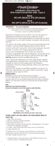
Digital/Relay Output On/Off Delay
A timer function has been implemented by adding four new software parameters.
Two are for the On Delay and two for the Off Delay timer to the digital outputs of the
VS1MD drive. Setting a value of greater than zero will begin the On, Off or both
timers when the condition set in t32 and t33 for the digital outputs is met.
In the case of the On delay timer, the actual output will not change state until the
time value set in t50 to t51 is met. The Condition set in t32 to t33 must be active
when the timer is reached for the output state to change.
In the case of the Off delay timer, once the output state is on, it will delay turning off
after the Off delay value is reached on t52 to t53. When the Off delay time is
reached, the condition set in t32 to t33 must still be off.
t50
t51
Digital Output (MO) On Delay
Relay Output (3A - 3C) On Delay
Range: 0 to 3,600 Seconds
Default: 0
Access: Configurable
See Also: t32 and t33
Sets the on delay timer for the digital output.
t52
t53
Digital Output (MO) Off Delay
Relay Output (3A - 3C) Off Delay
Range: 0 to 3,600 Seconds
Default: 0
Access: Configurable
See Also: t32 and t33
Sets the off delay timer for the digital output.
Output
MO or Relay State
On Delay Tme On Delay Time
Output
MO or Relay State
Off Delay Time
Off Delay Time

Contents I
Table of Contents
Chapter 1 Introduction
1.1 Getting Assistance from Baldor.......................................................................1-1
Chapter 2 General Information and Ratings
2.1 Identifying the Drive by Model Number ...........................................................2-1
2.2 VS1-MD Drive Ratings, Model Numbers and Frame Sizes.............................2-2
2.3 Storage Guidelines..........................................................................................2-2
Chapter 3 Installing the Drive
3.1 General Requirements for the Installation Site................................................3-1
3.2 Mounting the Drive ..........................................................................................3-5
3.3 Watts Loss Data..............................................................................................3-6
Chapter 4 Power Wiring
4.1 Grounding the Drive ........................................................................................4-1
4.2 Connecting Peripheral Devices to the VS1-MD Drive .....................................4-3
4.3 Power Terminal Wiring....................................................................................4
4.4 Specifications for Power Terminal Block Wiring .............................................4-5
4.5 Recommended Breakers.................................................................................4
4.6 Recommended AC Reactors...........................................................................4-6
Chapter 5 Control Wiring
5.1 Stop Circuit Requirements...............................................................................5-1
5.2 Motor Start/Stop Precautions ..........................................................................5-2
5.3 Terminal Wiring (Control I/O)...........................................................................5-3
5.4 Control Terminal Specifications.......................................................................5
5.5 Source/Sync for Input Control Wiring ..............................................................5-5
5.6 I/O Wiring Recommendations..........................................................................5-6
5.7 Technical Specifications..................................................................................5-6
Chapter 6 Using the Keypad
6.1 Keypad Components.......................................................................................6-1
6.2 LED Descriptions.............................................................................................6-2
6.3 Key Descriptions..............................................................................................6-2
6.4 About Parameters............................................................................................6-3
6.5 How Parameters are Organized......................................................................6-4
6.6 Moving Between Parameter Groups ...............................................................6-4
6.7 Changing Between Parameters Within a Group..............................................6-6
6.8 Modifying the Value of a Parameter................................................................6-8
6.9 Monitoring Display Parameters .....................................................................6-10
6.10 Reviewing the Fault Status in the Display Group..........................................6-11
6.11 Resetting the Parameters to Factory Default ................................................6-12
Chapter 7 Parameter Descriptions
7.1 Overview..........................................................................................................7-1
7.2 Display Group Parameters ..............................................................................7-2
7.3 Basic Group Parameters.................................................................................7-5
7.4 Terminal Paramters.......................................................................................7-12
7.5 Function Group 1 Parameters.......................................................................7-28
7.6 Function Group 2 Paramters .........................................................................7-40

II VS1MD User Manual
Chapter 8 Customizing for Your Application
8.1 Frequency Mode..............................................................................................8-1
8.2 UP-Down..........................................................................................................8
8.3 3-Wire ..............................................................................................................8
8.4 PID Control.....................................................................................................8
8.5 Auto-tuning.....................................................................................................8-
8.6 Sensorless Vector Control .............................................................................8
8.7 Speed Search ...............................................................................................8
8.8 Self-Diagnostic Function................................................................................8-17
8.9 Parameter Read/Write ...................................................................................8
8.10 Parameter Initialization / Lock........................................................................8-19
8.11 Multi-function Output Terminal (MO) and Relay (3AC)..................................8
8.12 Accel/Decel setting and V/F Control ..............................................................8-27
8.13 Control Block Diagram...................................................................................8-28
8.14 Frequency and Drive Mode Setting................................................................8-29
Chapter 9 Troubleshooting
9.1 Verifying that DC Bus Capacitors are Discharged Before
Servicing the Drive..........................................................................................9-1
9.2 Determining Drive Status Using the STP/FLT LED..........................................9-2
9.3 Monitoring Drive Status Using the Display Parameters...................................9-2
9.4 Reviewing Fault Status of the Drive.................................................................9-3
9.5 Fault Codes......................................................................................................9-3
9.6 Fault Correction................................................................................................9-6
9.7 Overload Protection .........................................................................................9-8
Appendix A Technical Specifications........................................................................................A-1
Appendix B Options & Kits
B.1 Remote Option................................................................................................B-1
B.2 Conduit Kit.......................................................................................................B-4
B.3 Breaking Resistor............................................................................................B-8
Appendix C RS485 Protocol
C.1 Introduction .....................................................................................................C-1
C.2 Specifications..................................................................................................C-2
C.3 Installation.......................................................................................................C-3
C.4 Operation ........................................................................................................C-3
C.5 Communication Protocol (MODMUS-RTU).....................................................C-4
C.6 Communication Protocol (LS BUS).................................................................C-4
C.7 Troubleshooting ..............................................................................................C-7

Introduction 1-1
CHAPTER 1
Introduction
This manual is intended for qualified electrical personnel familiar with installing,
programming, and maintaining AC Drives.
This manual contains information on:
• Installing and wiring the VS1MD drive
• Programming the drive
• Troubleshooting the drive
1.1 Getting Assistance from Baldor
For technical assistance, call 1-864-284-5444. Before calling, please review the
troubleshooting section of this manual and check the Baldor Drives website at
www.reliance.com/vsdrives for additional information. When you call technical
support, you will be asked for the drive model number or catalog number and this
instruction manual number.

1-2 VS1MD AC Drive User Manual

General Information and Ratings 2-1
CHAPTER 2
General Information and Ratings
The VS1MD is a variable frequency PWM drive capable of operating in open-loop,
volts-per-hertz mode and in a sensorless vector control (SVC) mode.
This chapter contains information about the VS1MD drive, including how to identify
the drive.
2.1 Identifying the Drive by Model Number
Each drive can be identified by its model number, as shown in figure 2.1. The model
number is on the shipping label and the drive nameplate. The model number includes
the drive and any options.
Drive model numbers for the VS1MD drive are provided in table 2.1.
Figure 2.1 – Identifying the Drive by Model Number
VS1 MD 4 10
HP
0P5 = 0.5HP
1 = 1HP
2 = 2HP
3 = 3HP
5 = 5HP
7 = 7.5 HP
10 = 10HP
Voltage:
2 = 230V
4 = 460V
Family
MD = Microdrive

2-2 VS1MD AC Drive User Manual
2.2 VS1MD Drive Ratings, Model Numbers and Frame
Sizes
Similar VS1MD drive sizes are grouped into frame sizes to simplify re-ordering and
dimensioning. Refer to figures 3.2 through 3.5 for the dimensions of each frame size.
Table 2.1 provides VS1MD drive ratings, model numbers and frame sizes.
2.3 Storage Guidelines
If you need to store the drive, follow these recommendations to prolong drive life and
performance:
• Store the drive within an ambient temperature range of -40
o
to +70 C
o
.
• Store the drive within a relative humidity range of 0% to 90%, non-condensing.
Do not expose the drive to a corrosive atmosphere.
Table 2.1 – Drive Ratings, Model Numbers and Frame Sizes
Drive Ratings Model Number Frame
Size
Input Voltage kW HP Output
Current
200-230V
3-Phase
0.4 0.5 2.5 VS1MD20P5 A
0.75 1.0 4.5 VS1MD21 A
1.5 2.0 8.0 VS1MD22 B
2.2 3.0 12.0 VS1MD23 C
3.7 5.0 17.0 VS1MD25 C
5.5 7.5 24.0 VS1MD27 D
7.5 10 32.0 VS1MD210 D
380-480V
3-Phase
0.4 0.5 1.25 VS1MD40P5 A
0.75 1.0 2.5 VS1MD41 A
1.5 2.0 4.0 VS1MD42 B
2.2 3.0 6.0 VS1MD43 C
3.7 5.0 8.0 VS1MD45 C
5.5 7.5 12.0 VS1MD47 D
7.5 10.0 16.0 VS1MD410 D

Installing the Drive 3-1
CHAPTER 3
Installing the Drive
This chapter provides information that must be considered when planning a VS1MD
drive installation and provides drive mounting information and installation site
requirements.
3.1 General Requirements for the Installation Site
It is important to properly plan before installing a VS1MD to ensure that the drive’s
environment and operating conditions are satisfactory.
The area behind the drive must be kept clear of all control and power wiring. Power
connections may create electromagnetic fields that may interfere with control wiring or
components when run in close proximity to the drive.
Read the recommendations in the following sections before continuing with the drive
installation.
!
ATTENTION: Only qualified electical personnel familiar with the
construction and operation of this equipment and the hazards involved
should install, adjust, operate, or service this equipment. Read and
understand this manual and other applicable manuals in their entirety
before proceeding. Failure to observe this precaution could result in
severe bodily injury or loss of life.
ATTENTION: Use of power correction capacitors on the output of
the drive can result in erratic operation of the motor, nuisance tripping,
and/or permanent damage to the drive. Remove power correction
capacitors before proceeding. Failure to observe this precaution could
result in damage to, or destruction of, the equipment.
ATTENTION: The user is responsible for conforming with all
applicable local, national, and international codes. Failure to observe
this precaution could result in damage to, or destruction of, the
equipment.

3-2 VS1MD AC Drive User Manual
3.1.1 Operating Conditions
Before deciding on an installation site, consider the following guidelines:
• Protect the cooling fan by avoiding dust or metallic particles.
• Do not expose the drive to a corrosive atmosphere.
• Protect the drive from moisture and direct sunlight.
• Verify that the drive location will meet the environmental conditions specified in table
3.1.
3.1.2 Minimum Mounting Clearances
Refer to figure 3.1 for the minimum mounting clearances. Refer to section 3.1 for drive mounting
dimensions.
Table 3.1 – Ambient Temperatures and Mounting Clearances
Ambient Temperature Enclosure Rating Minimum Mounting
Clearances
Minimum Maximum
-10
o
C
(14
o
F)
50
o
C
(122
o
F)
IP20/Open Type 5 cm
40
o
C
(104
o
F)
IP20/NEMA 1 5 cm
50
o
C
(122
o
F)
Side-by-Side 5 cm
Figure 3.1 – Minimum Mounting Clearances
5 cm
(1.0 in)

Installing the Drive 3-3
3.1.3 Mounting Dimensions for the VS1MD Drive
Overall dimensions and weights are illustrated in figures 3.2, 3.3, 3.4 and 3.5 as an aid to
calculating the total area required by the VS1-MD drive. Dimensions are in millimeters. Weights
are in kilograms. See table 2.1 for drive ratings by frame.
Frame Size A HP W W1 H H1 D A B kg
230V/460V 0.5 70 65.5 128 119 130 4.5 4.0 0.76
230V/460V 1.0 70 65.5 128 119 130 4.5 4.0 0.77
Figure 3.2 – Drive Dimensions and Weights Frame A
W
W1
A
D
H
W1
B
H1
A

3-4 VS1MD AC Drive User Manual
Frame Size B HP W W1 H H1 D A B kg
230V/460V 2.0 100 95.5 128 120 130 4.5 4.5 1.12
Figure 3.3 – Drive Dimensions and Weights Frame B
Frame Size C HP W W1 H H1 D A B kg
230V/460V 3.0 140 132 128 120.5 155 4.5 4.5 1.84
230V/460V 5.0 140 132 128 120.5 155 4.5 4.5 1.89
Figure 3.4 – Drive Dimensions and Weights Frame C
W
W1
D
H
H1
W1
B
A
A
W
W1
D
H
H1
A
B
B

Installing the Drive 3-5
3.2 Mounting the Drive
Mount the drive upright on a flat, vertical, and level surface.
3.2.1 Protecting the Drive from Debris
The drive must be protected from debris falling through the vents in the top of the drive
during installation and operation. The drive is designed to operate in IP20/Open Type
application mounted in a protective enclosure. A conduit kit is available as an option
which provides a top panel to block the top vents and prevent debris from entering the
drive.
Frame Size D HP W W1 H H1 D A B kg
230V/460V 7.5 180 170 220 210 170 5.0 4.5 3.66
230V/460V 10.0 180 170 220 210 170 5.0 4.5 3.66
Figure 3.5 – Drive Dimensions and Weights Frame D
W
W
A
A
D
W1
H
H1
B
B
Table 3.1 – Mounting Specifications
Frame Screw Size Screw Torque
A M3.5 (#6-32) 0.67 - 0.97 N-m (6 - 8 in-lb)
B M4 (#8-32) 1.56 - 1.96 N-m (14 -17 in-lb)
C M4 (#8-32) 1.56 - 1.96 N-m (14 -17 in-lb)
D M4 (#8-32) 1.56 - 1.96 N-m (14 -17 in-lb)

3-6 VS1MD AC Drive User Manual
3.3 Watts Loss Data
Table 3.2 – Watts Loss Data
Model # HP Frame Watts Loss
230 Volts
VS1MD20P5 0.5 A 13
VS1MD21 1.0 A 28
VS1MD22 2.0 B 18
VS1MD23 3.0 C 56
VS1MD25 5.0 C 98
VS1MD27 7.5 D 73
VS1MD210 10.0 D 70
460 Volts
VS1MD40P5 0.5 A 9
VS1MD41 1.0 A 22
VS1MD42 2.0 B 32
VS1MD43 3.0 C 47
VS1MD45 5.0 C 94
VS1MD47 7.5 D 84
VS1MD410 10.0 D 113

Power Wiring 4-1
CHAPTER 4
Power Wiring
4.1 Grounding the Drive
The drive Safety Ground - must be connected to system ground. Ground impedance must
conform to the requirements of national and local industrial safety regulations and/or electrical
codes. The integrity of all ground connections should be periodically checked.
Ground Fault Monitoring
If a system ground fault monitor is to be used, only Type B devices should be used to
avoid nuisance tripping.
Safety Ground -
This is the safety ground for the drive that is required by code. One of these points must be
connected to adjacent building steel (girder, joist), a floor ground rod, or bus bar. Grounding
points must comply with national and local industrial safety regulations and/or electrical codes.
Motor Ground
The motor ground must be connected to one of the ground terminals on the drive.
!
ATTENTION:The following information is merely a guide for proper
installation. Baldor Electric Company cannot assume responsibility for
the compliance or the noncompliance to any code, national, local or
otherwise for the proper installation of this drive or associated equipment.
A hazard of personal injury and/or equipment damage exists if codes are
ignored during installation.
ATTENTION:Use the dedicated ground terminal to ground the drive. Do
not use the screw in the case or chassis, etc for grounding.
Figure 4.1 – Typical Grounding
SHLD
U
V
W
R
S
T

4-2 VS1MD AC Drive User Manual
Shield Termination - SHLD
Either of the safety ground terminals provides a grounding point for the motor cable shield. The
motor cable shield connected to one of these terminals (drive end) should also be connected to
the motor frame (motor end). Use a shield terminating or EMI clamp to connect the shield to the
safety ground terminal.
When shielded cable is used for control and signal wiring, the shield should be grounded at
the source end only, not at the drive end.
4.1.1 RFI Filter Grounding
Using drives with RFI filters may result in relatively high ground leakage currents. Therefore, the
filter must only be used in installations with grounded AC supply systems and be
permanently installed and solidly grounded (bonded) to the building power distribution
ground.
Ensure that the incoming supply neutral is solidly connected (bonded) to the same building
power distribution ground. Grounding must not rely on flexible cables and should not include
any form of plug or socket that would permit inadvertent disconnection. Some local codes may
require redundant ground connections. The integrity of all connections should be periodically
checked.
4.1.2 Grounding Procedure
Step 1. Remove the front cover.
Step 2. Connect the Grounding wire to the ground terminal through the opening for
ground terminal. Enter the screw driver from vertical to the terminal and
secure the screw tightly.
4.1.3 Grounding Guidelines
Table 4.1 – Grounding Guidelines
Inverter
capacity
200V Class 400V Class
Wire
size
Terminal
screw
Grounding
method
Wire
size
Terminal
screw
Grounding
method
0.5 HP 3.5 mm
2
M3 Type 3 2 mm
2
M3 Special Type 3
1.0 HP 3.5 mm
2
M3 2 mm
2
M3
2.0 HP 3.5 mm
2
M3 2 mm
2
M3
3.0 HP 3.5 mm
2
M3 2 mm
2
M3
7.5 HP 5.5 mm
2
M4 3.5 mm
2
M4
/