Omnitron iConverter T1/E1 User manual
- Category
- Network media converters
- Type
- User manual
This manual is also suitable for

iConverter
®
T1/E1 Standalone Module USER MANUAL
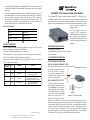
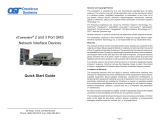
The iConverter T1/E1 media converter provides standard T1 (1.544Mbps) or E1
(2.048Mbps) copper to fiber conversion and can be used to extend the demarcation
point between service provider and networking equipment. T1/E1 media converters
operate in pairs, extending distances over fiber, which improves noise immunity, quality
of service, intrusion protection and
network security.
The T1/E1 supports Small Form
Pluggable (SFP) transceivers,
enabling adaptability to different fiber
types, distances and wavelengths,
providing maximum flexibility across
a variety of network architectures and
topologies.
INSTALLATION PROCEDURE
1) Configure DIP-Switches
2) Install Standalone Module and Connect Cables
3) Verify Operation
1) CONFIGURE DIP-SWITCHES
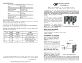
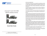
FRONT PANEL DIP-SWITCHES
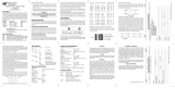
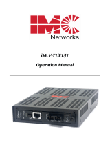
SW1 - LOCAL DUAL LOOP-BACK “LOOP”
When this DIP-switch is set to the “Loop” position, it sets the
iConverter T1/E1 converter
to a dual loop-back mode (see Figure
B) on both the fiber and copper
connections. By returning the DIP-
switch to the “Norm” position, the unit
resumes normal operation.
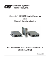
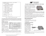
SW2 - FIBER OPTIC TEST “FOT”
This DIP-switch will allow the entire
fiber segment to be tested at either
of the iConverter T1/E1 converters
without having to set DIP-switches
on both units. When this DIP-switch
is set to “FOT”, the local unit (the unit
with the DIP-switch in the “FOT”
position) is switched into local loop-
back mode. In addition to the local loop-back mode of operation, the fiber TX port is
further encoded to carry a remote loop-back protocol. This remote loop-back protocol
sets the remote unit at the other end of the fiber link to a remote loop-back mode of
operation and returns a signal to the local unit (see Figure C). A fast blinking “Tst” LED
on the local unit and a slow blinking “Tst” LED on the remote unit shows confirmation
that the fiber segment is communicating properly between devices. By returning the
DIP-switch to the “Norm” position, the units resumes normal operation.
c. Connect to the RJ-45/48 connector on the iConverter T1/E1 converter via a Category 3
or better cable (Category 5 is recommended), and attach the other end to the network
equipment.
d. Connect an appropriate multimode or single-mode fiber cable to the fiber port of
the installed module. It is important to ensure that the transmit (TX) is attached to
the receive side of the device at the other end and the receive (RX) is attached to
the transmit side. Single-fiber (SF) media converter models operate in pairs. The
TX wavelength must match the RX wavelength at the other end and the RX
wavelength must match the TX wavelength at the other end.
CABLE SPECIFICATIONS:
UTP Cable for T1 and E1
Gauge 22 to 24 AWG
Impedance 100 ohms +/- 10%
Impedance Characteristic 2.6dB/100M @ 1Mhz
Maximum Distance T1 6,000 ft E1 8,000 ft
3) VERIFY OPERATION
Once the module has been installed and configured per steps 1 and 2, verify the
module is operational by viewing the LED indicators.
The Power LED indicates the module is receiving power.
The Fiber Optic link LED indicates the fiber optic connection has been established.
The UTP LED indicates a T1/E1 signal has been detected.
If the Fiber Optic LED is blinking, the port is receiving an all 1s signal. This will occur
if the UTP port is not connected.
LED Function
"Legend"
Color OFF State ON State
Power
"Pwr"
Amber No power Module has power
Fiber Optics
"F/O Lk"
Green No Fiber Link
On: Fiber signal detected
Blinking: All ones received
Test
"Tst"
Green Normal
On: Loop or All ones Test Mode
Blinking: FOT Received - Local
Fast Blinking: FOT Received - Remote
UTP
"UTP Lk"
Green No UTP Link
On: UTP signal detected
Blinking: All ones received
Form 040-08700-001 J 7/08
Omnitron Systems Technology * 140 Technology Dr. #500 * Irvine, CA 92618
949.250.6510 tel * 949.250.6514 fax * www.omnitron-systems.com
Figure A: DIP-Switch Location

Line Type Port Type Distance
DIP-Switch Position
1234
T1 DSX-1 RJ-45/48 0' to 133'
LLLL
T1 DSX-1 RJ-45/48 133' to 266'
LLLK
T1 DSX-1 RJ-45/48 266' to 399'
LLKL
T1 DSX-1 RJ-45/48 399' to 533'
LLKK
T1 DSX-1 RJ-45/48 533' to 655'
LKLL
T1 DS1 RJ-45/48 0 dB
LLLL
T1 DS1 RJ-45/48 -7.5 dB
LKLK
T1 DS1 RJ-45/48 -15 dB
LKKL
T1 DS1 RJ-45/48 -22.5 dB
LKKK
E1 120 ohm RJ-45/48 Standard
KLLK
E1 120 ohm RJ-45/48 Extended
KLKK
2) INSTALL STANDALONE MODULE AND CONNECT CABLES
a. The T1/E1 Converter is available in wall-mount models. For wall-mounting, attach
the unit to a wall, backboard or other flat surfaces.
To power the unit using the AC/DC adapter, connect the AC/DC adapter to the AC
outlet. Then connect the barrel plug at the end of the wire on the AC/DC adapter to
the 2.5mm DC barrel connector (center-positive) on the chassis. Confirm that the
unit has powered up properly by checking the power status LED located on the
front of the unit.
To power the unit using a DC power source, prepare a power cable using a two-
conductor insulated wire (not supplied) with a 14 AWG gauge minimum. Cut the
power cable to the length required. Strip approximately 3/8 of an inch of insulation
from the power cable wires. Connect the power cables to the standalone unit by
fastening the stripped ends to the DC power connector.
Connect the power wires to the DC power source. The Power LED should indicate
the presence of power.
WARNING: Note the wire colors used in making the positive and negative
connections. Use the same color assignment for the connection at the DC
power source.
NOTE: If mounting with a safety ground attachment, use the safety ground
screw at the rear of the unit.
b. When using the SFP model (8719-0 or 8759-0), insert the SFP Fiber transceiver
into the Port 1 SFP receptacle on the T1/E1 converter (see the SFP Data Sheet
091-17000-001 for supported transceivers).
NOTE: The release latch of the SFP Fiber transceiver must be in the closed
(up) position before insertion.
Figure B: Dual Loopback Mode
Figure C: Fiber Optic Test Mode
SW3 - FORCE 1S TO FIBER “FO1”
When this DIP-switch is set to the “FO1” position, an “all ones” pattern is
inserted into the data stream being transmitted out of the fiber port on the
T1/E1 converter. Data being received on the coax or twisted pair is disabled and
data being received on the fiber is passed through to the coax or twisted pair side. A
blinking “Tst” LED on the remote T1/E1 shows confirmation that the fiber segment is
communicating properly between the devices. By returning the DIP-switch to the “Norm”
position, the unit resumes normal operation.
SW4 - FORCE 1S TO COAX OR UTP “CU1”
When this DIP-switch is set to the “Cu1” position, an “all ones” pattern is inserted into
the data stream being transmitted out of the coax or twisted pair port on the
T1/E1 converter. Data being received on the fiber will be disabled and data being
received on the coax or twisted pair is passed through to the fiber side. A blinking “Tst”
LED on the remote T1/E1 shows confirmation that the Coax or UTP segment is
communicating properly between the devices. By returning the DIP-switch to the “Norm”
position, the unit resumes normal operation.
SW1 AND SW2 - AMI/B8ZS/HDB3 MODE
B8ZS (T1) or HDB3 (E1) is the default line encoding mode of operation. To select AMI
mode enable both the Local Dual Loop-back “Loop” and Fiber Optic Test “FOT”
DIP-switches on the front of the module.
PUSH BUTTON - MANUAL CROSSOVER “= / X”
The Manual Crossover “= / X” button located on the front panel is used to eliminate the
need for crossover and custom cables when connecting devices to the RJ-45/48 port.
When the button is in the out “=” position, the port is configured for a straight-through
cable. When the button is in the in “X” position, the port is configured for a crossover
cable. The twisted pair connection requires two active pairs in a T1/E1 environment.
The active pairs are pins 1 & 2 and pins 4 & 5. Only dedicated wire pairs should be
used for the active pins.
DIP-SWITCH BANK 1
BOARD MOUNTED DIP-SWITCH SETTINGS:
T1/E1 Copper Line Configuration Settings:
The T1/E1 copper line codes and line lengths are configured using board mounted
DIP-switches.
-
 1
1
-
 2
2


Omnitron iConverter T1/E1 User manual
- Category
- Network media converters
- Type
- User manual
- This manual is also suitable for
Ask a question and I''ll find the answer in the document
Finding information in a document is now easier with AI
Related papers
-
 Omnitron Systems Technology iConverter T1/E1 Plug-in Owner's manual
-
Omnitron iConverter T1/E1 Specification
-
Omnitron Systems Technology iconverter t3 User manual
-
-
-
Omnitron Systems Technology iConverter GXTM User manual
-
 Omnitron Systems Technology 4472/92-0 User manual
-
Omnitron Systems Technology GX/TM2 Standalone User manual
-
-
Omnitron Systems Technology iConverter 10/100M2 User manual


Other documents
-
-
 Omnitron Systems Technology iConverter Gx AN Owner's manual
-
 Omnitron Systems Technology Omnitron iConverter 10/100M User manual
-
 Omnitron Systems Technology iConverter GM3 NID 2 and 3 Port Quick Start
-
Black Box T1/E1 User manual
-
 Omnitron Systems Technology iConverter GM4 NID 2 & 3 Port Quick Start
-
 IMC Networks iMcV-T1 User manual
-
 Omnitron Systems Technology iConverter 10/100M User manual
-
 Omnitron Systems Technology 2-Port GM3 Standalone Fiber-to-Copper Quick Start
-
Omnitron Systems Technology 2-Port GM4 Fiber to Fiber Standalone Quick start guide


