MQ Power DCA-45USI Specification
- Category
- Trash Compactor
- Type
- Specification
This manual is also suitable for

PARTS AND OPERATION MANUAL
OPERATION AND PARTS MANUAL
PARTS LIST NO. M1870300034A
Revision #7 (06/13/07)
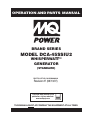
BRAND SERIES
MODEL DCA-45SSIU2
WHISPERWATT™
GENERATOR
(STANDARD)
THIS MANUAL MUST ACCOMPANY THE EQUIPMENT AT ALL TIMES.
To find the latest revision of this
publication, visit our website at:
www.multiquip.com

PAGE 2 — DCA-45SSIU2 — OPERATION AND PARTS MANUAL (STD) — REV. #7 (06/13/07)
Diesel engine exhaust and some of

DCA-45SSIU2 — OPERATION AND PARTS MANUAL (STD) — REV. #7 (06/13/07) — PAGE 3
NOTE PAGE

PAGE 4 — DCA-45SSIU2 — OPERATION AND PARTS MANUAL (STD) — REV. #7 (06/13/07)
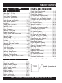
TABLE OF CONTENTS
MQ POWER DCA-45SSIU2MQ POWER DCA-45SSIU2
MQ POWER DCA-45SSIU2MQ POWER DCA-45SSIU2
MQ POWER DCA-45SSIU2
AC GENERAAC GENERA
AC GENERAAC GENERA
AC GENERA
TORTOR
TORTOR
TOR
Here's How To Get Help ............................................. 3
Table Of Contents ....................................................... 4
Parts Ordering Procedures ........................................ 5
DCA-45SSIU2 Specifications...................................... 6
Dimensions ............................................................... 7-8
Safety Message Alert Symbols ........................... 10-11
Rules for Safe Operation ..................................... 12-15
Installation ............................................................ 16-17
Towing Safety Precautions ....................................... 18
Trailer Specifications ............................................ 19-21
Generator Decals ................................................. 22-23
General Information .................................................. 24
Major Components ................................................... 25
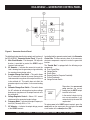
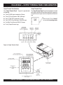
Generator Control Panel........................................... 26
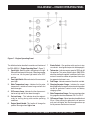
Engine Operating Panel ............................................ 27
Output Terminal Panel Familiarization................. 28-30
Load Application........................................................ 31
Generator Outputs ............................................... 32-33
Gauge Reading ......................................................... 33
Output Terminal Panel Connections .................... 34-35
Pre-setup .............................................................. 36-40
Generator Start-up Procedure ............................41-43
Generator Shut-down Procedure ............................. 44
Maintenance......................................................... 45-47
Trailer Brakes Maintenance...................................... 48
Trailer Maintenance .............................................49-50
Trailer Wiring Diagram .............................................. 51
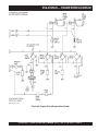
Engine Wiring Diagram ........................................ 52-53
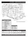
Generator Wiring Diagram ....................................... 54
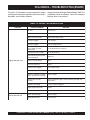
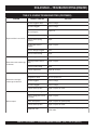
Engine Troubleshooting ....................................... 55-56
Generator Troubleshooting....................................... 57
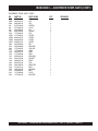
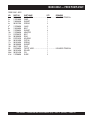
Explanation of Codes in Remarks Column .............. 58
Suggested Spare Parts ............................................ 59
Specification and part
number are subject to
change without notice.
NOTE
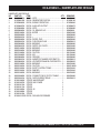
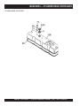
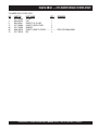
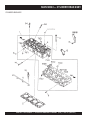
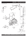
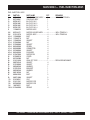
ISUZU 4BG1 ENGINE
Cylinder Head Cover Assembly ......................... 86-87
Cylinder Head Assembly .................................... 88-89
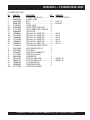
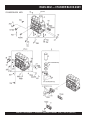
Cylinder Block Assembly .................................... 90-91
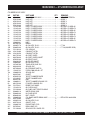
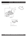
Oil Pan and Level Gauge Assembly ................... 92-93
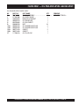
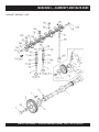
Camshaft and Valve Assembly ........................... 94-95
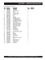
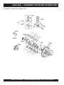
Crankshaft, Piston and Flywheel Assembly ...... 96-97
Timing Gear and Flywheel Housing Assembly ........ 98-99
Engine Mounting Assembly ............................ 100-101
Inlet Manifold Assembly .................................. 102-103
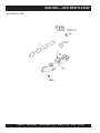
Exhaust Manifold Assembly ............................ 104-105
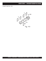
Ventilation Assembly ....................................... 106-107
Water Pump and Corrosion Resistor Assembly ... 108-109
Thermostat and Housing Assembly ............... 110-111
Engine Water Piping Assembly ....................... 112-113
Fan and Fan Belt Assembly ............................ 114-115
Fuel Injection Assembly .................................. 116-117
Fuel Filter and Bracket Assembly .................. 118-119
Fuel Pump and Piping Assembly ................... 120-121
Oil Cooler and Oil Filter Assembly ................. 122-123
Oil Pump and Oil Strainer Assembly .............. 124-125
Oil and Vacuum Piping Assembly ................... 126-127
Electrical Control Assembly ............................ 128-129
Battery Relay Assembly .................................. 130-131
Starter Component Assembly ........................ 132-133
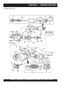
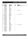
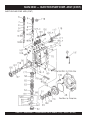
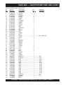
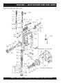
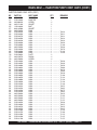
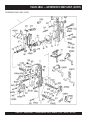
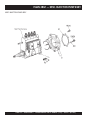
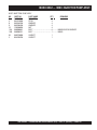
Inj. Pump Component Assembly .................... 134-137
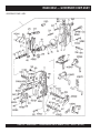
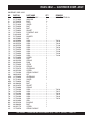
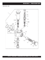
Governor Component Assembly .................... 138-141
Feed Pump Assembly ..................................... 142-143
Misc. Inj. Pump Assembly ............................... 144-145
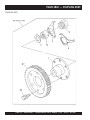
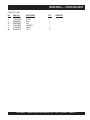
Coupling Assembly ......................................... 146-147
Accelerator Pedal Assembly ........................... 148-149
Air Duct Assembly ........................................... 150-151
Fuel Sedimenter Assembly ............................ 152-153
Clutch Assembly.............................................. 154-155
Switch and Relay Assembly ............................ 156-157
Terms and Condition of Sale — Parts .................. 158
COMPONENT DRACOMPONENT DRA
COMPONENT DRACOMPONENT DRA
COMPONENT DRA
WINGSWINGS
WINGSWINGS
WINGS
Generator Assembly ........................................... 60-61
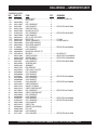
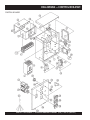
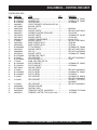
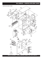
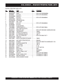
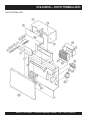
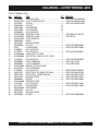
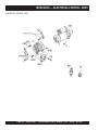
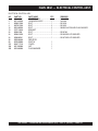
Control Box Assembly ......................................... 62-65
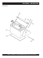
Engine & Radiator Assembly .............................. 66-67
Engine Operating Panel Assembly..................... 68-69
Output Terminal Assembly .................................. 70-71
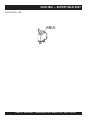
Battery Assembly ................................................ 72-73
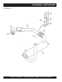
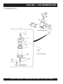
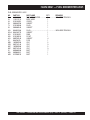
Muffler Assembly ................................................ 74-75
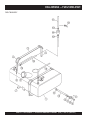
Fuel Tank Assembly ............................................ 76-77
Enclosure Assembly ........................................... 78-81
Rubber Seal Assembly ....................................... 82-83
Name Plate And Decals ...................................... 84-85

DCA-45SSIU2 — OPERATION AND PARTS MANUAL (STD) — REV. #7 (06/13/07) — PAGE 5
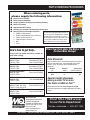
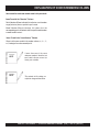
PARTS ORDERING PROCEDURES
When ordering parts,
please supply the following information:
❒❒
❒❒
❒ Dealer account number
❒❒
❒❒
❒ Dealer name and address
❒❒
❒❒
❒ Shipping address (if different than billing address)
❒❒
❒❒
❒ Return fax number
❒❒
❒❒
❒ Applicable model number
❒❒
❒❒
❒ Quantity, part number and description of each part
❒❒
❒❒
❒ Specify preferred method of shipment:
✓ FedEx or UPS Ground
✓ FedEx or UPS Second Day or Third Day
✓ FedEx or UPS Next Day
✓ Federal Express Priority One
✓ DHL
✓ Tr uck
Here’s how to get help...
Please have the model and serial number on
hand when calling.
Parts Department
800-427-1244 Fax: 800-672-7877
310-537-3700 Fax: 310-637-3284
Mayco Parts
800-306-2926 Fax: 800-672-7877
310-537-3700 Fax: 310-637-3284
Service Department
800-478-1244 Fax: 310-537-4259
310-537-3700
MQ Power Service Department
800-835-2551 Fax: 310-638-8046
310-537-3700
Warranty Department
800-421-1244, Ext. 279 Fax: 310-537-1173
310-537-3700, Ext. 279
Multiquip’s Main Phone Numbers
800-421-1244 Fax: 310-537-3927
310-537-3700
Note: Unless otherwise indicated by customer, all
orders are treated as “Standard Orders”, and will
ship within 24 hours. We will make every effort to
ship “Air Shipments” the same day that the order is
received, if prior to 2PM west coast time. “Stock
Orders” must be so noted on fax or web forms.
Extra Discounts!
All parts orders which include complete part numbers
and are received by our automated web parts order
system, or by fax qualify for the following extra
discounts:
Ordered Standard Stock orders
via orders ($750 list and above)
Fax 3% 10%
Web 5% 10%
Special freight allowances
when you order 10 or more
line items via Web or Fax!**
FedEx Ground Service
at no charge for freight
No other allowances on freight shipped by any other
carrier.
Place Your Parts Order Via Web or Fax
For Even More Savings!
NOTE: DISCOUNTS ARE SUBJECT TO CHANGE
MULTIQUIP INC.
18910 WILMINGTON AVENUE
POST OFFICE BOX 6254
CARSON, CALIFORNIA 90749
310-537-3700 • 800-421-1244
FAX: 310-537-3927
E-MAIL: [email protected]
WWW: multiquip.com
Direct TOLL-FREE access
to our Parts Department:
Toll-free nationwide — 800-427-1244

PAGE 6 — DCA-45SSIU2 — OPERATION AND PARTS MANUAL (STD) — REV. #7 (06/13/07)
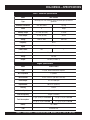
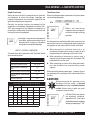
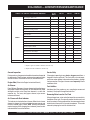
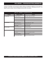
DCA-45SSIU2 — SPECIFICATIONS
snoitacificepSrotareneG.1elbaT
ledoM2UISS54-ACD
epyT
suonorhcnysepytdetcetorpnepo,detalitnevfles,dleifgnivloveR
rotareneg
noitcennoCeruta
mrA
lartueNhtiwratSgaZgiZ
esahP
3elgniS
tuptuOybdnatS
)WK2.83(AVK7.74WK6.72
tuptuOemirP
)WK63(AVK54WK62
egatloV
V0
84roV042V021/042
ycneuqerF
zH06
deepS
mpr008,1
rotcaFrewoP
8.01
rewoPCA.xuA
zH06,esahPelgniS
egatloV
CAV021
tuptuO
)2xWK4.2(WK8.4
snoitacificepSenignE
ledoM1GB4-BUZUSI
epyT
noitcejnitcerid,delooc-retaw,elcyC4
srednilyCfo.oN
srednilyc4
ekortSxeroB
)mm521xmm501
(.ni29.4x.ni31.4
tuptuOdetaR
mpr008,1/PH2.55
tnemecalpsiD
)cc293,4(.ni.uc862
gnitratS
cirtcelE
yticapaCtnalo
oC
)sretil02(.lag3.5
yticapaCliOebuL
)sretil9.21(.lag4.3
noitpmusnoCleuF
tarh/)L3.01(.lag7.2 daollluf tarh/)
L6.7(.lag0.2 daol4/3
tarh/)L7.5(.lag5.1 daol2/1 tarh/)L2.4(.lag1.1 daol4/1
yrettaB
HA001-V21
leuF
leuFleseiD2#

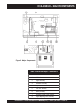
DCA-45SSIU2 — OPERATION AND PARTS MANUAL (STD) — REV. #7 (06/13/07) — PAGE 7
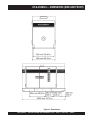
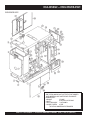
DCA-45SSIU2 — DIMENSIONS (SIDE AND FRONT)
Figure 1. Dimensions

PAGE 8 — DCA-45SSIU2 — OPERATION AND PARTS MANUAL (STD) — REV. #7 (06/13/07)
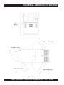
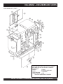
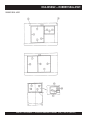
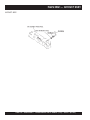
DCA-45SSIU2 — DIMENSIONS (TOP AND REAR)
Figure 2. Dimensions

DCA-45SSIU2 — OPERATION AND PARTS MANUAL (STD) — REV. #7 (06/13/07) — PAGE 9
NOTE PAGE

PAGE 10 — DCA-45SSIU2 — OPERATION AND PARTS MANUAL (STD) — REV. #7 (06/13/07)
DCA-45SSIU2 — SAFETY MESSAGE ALERT SYMBOLS
This Owner's Manual has been
developed to provide complete
instructions for the safe and efficient
operation of the MQ Power
Model
DCA45SSIU2 WHISPERWATT™
GENERATOR.
Before using this GENERATOR, ensure that the operating
individual has read and understands all instructions in this
manual.
Safety precautions should be followed at all times when operating
this equipment. Failure to read and understand the Safety
Messages and Operating Instructions could result in injury to
yourself and others.
FOR YOUR SAFETY AND THE SAFETY OF OTHERS!
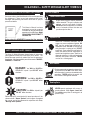
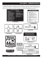
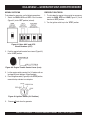
SAFETY MESSAGE ALERT SYMBOLS
The three (3) Safety Messages shown below will inform you
about potential hazards that could injure you or others. The
Safety Messages specifically address the level of exposure to
the operator, and are preceded by one of three words: DANGER,
WARNING, or CAUTION.
DANGER: You WILL be KILLED or
SERIOUSLY injured if you DO NOT follow
directions.
WARNING: You CAN be KILLED or
SERIOUSLY injured if you DO NOT follow
directions.
CAUTION: You CAN be injured if you
DO NOT follow directions.
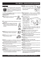
HAZARD SYMBOLS
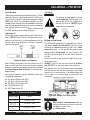
Engine exhaust gases contain poisonous
carbon monoxide. This gas is colorless and
odorless, and can cause death if inhaled.
NEVER operate this equipment in a confined
area or enclosed structure that does not
provide ample free flow air.
Potential hazards associated with trowel operation will be
referenced with "
Hazard Symbols
" which appear throughout
this manual, and will be referenced in conjunction with Safety
"
Message Alert Symbols
".
Diesel fuel is extremely flammable, and its
vapors can cause an explosion if ignited. DO
NOT start the engine near spilled fuel or
combustible fluids. DO NOT fill the fuel tank
while the engine is running or hot. DO NOT
overfill tank, since spilled fuel could ignite if it
comes into contact with hot engine parts or
sparks from the ignition system. Store fuel in
approved containers, in well-ventilated areas
and away from sparks and flames. NEVER
use fuel as a cleaning agent.
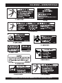
Burn Hazards
Engine components can generate extreme heat.
To prevent burns, DO NOT touch these areas
while the engine is running or immediately after
operations. NEVER operate the engine with
heat shields or heat guards removed.
Rotating Parts
NEVER operate equipment with covers, or
guards removed. Keep
fingers
,
hands
,
hair
and
clothing
away from all moving parts to
prevent injury.
Explosive Fuel
Lethal Exhaust Gases
NOTE

DCA-45SSIU2 — OPERATION AND PARTS MANUAL (STD) — REV. #7 (06/13/07) — PAGE 11
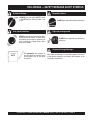
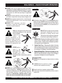
Accidental Starting
ALWAYS place the engine ON/OFF switch
in the OFF position, when the trowel is not
in use.
Over Speed Conditions
NEVER tamper with the factory settings of the
engine governor or settings. Personal injury
and damage to the engine or equipment can
result if operating in speed ranges above
maximum allowable.
Respiratory Hazard
ALWAYS wear approved respiratory protection.
ALWAYS wear approved eye and hearing
protection.
Sight and Hearing hazard
Equipment Damage Messages
Other important messages are provided throughout this manual
to help prevent damage to your trowel, other property, or the
surrounding environment.
This
generator
, other property, or
the surrounding environment could
be damaged if you do not follow
instructions.
NOTE
DCA-45SSIU2 — SAFETY MESSAGE ALERT SYMBOLS

PAGE 12 — DCA-45SSIU2 — OPERATION AND PARTS MANUAL (STD) — REV. #7 (06/13/07)
DCA-45SSIU2 — RULES FOR SAFE OPERATION
CAUTIONCAUTION
CAUTIONCAUTION
CAUTION
:
Failure to follow instructions in this manual may
lead to serious injury or even death! This
equipment is to be operated by trained and
qualified personnel only! This equipment is for
industrial use only.
The following safety guidelines should always be used when
operating the DCA-45SSIU2 Generator:
GENERAL SAFETY
■
DO NOT operate or service this equipment
before reading this entire manual.
■
This equipment should not be operated by persons under 18
years of age.
■
NEVER operate this equipment without proper
protective clothing, shatterproof glasses, steel-
toed boots and other protective devices required
by the job.
■
NEVER operate this equipment when not feeling
well due to fatigue, illness or taking medicine.
■
NEVER operate this equipment under the
influence or drugs or alcohol.
■
NEVER use accessories or attachments, which are not
recommended by MQ Power for this equipment. Damage to
the equipment and/or injury to user may result.
■
Manufacture does not assume responsibility for any accident
due to equipment modifications.
■
Whenever necessary, replace nameplate, operation and
safety decals when they become difficult read.
■
ALWAYS check the machine for loosened threads or bolts
before starting.
■
NEVER operate the generator in an explosive atmosphere or
near combustible materials. An explosion or fire could result
causing severe
bodily harm or even death.
■
High Temperatures – Allow the engine to cool before
performing service and maintenance functions. Contact
with
hot!
components can cause serious burns.
■
The engine of this
generator requires an
adequate free flow of
cooling air.
NEVER
operate the generator
in any enclosed or
narrow area where free
flow of the air is
restricted. If the air flow
is restricted it will
cause serious damage to the generator or engine and
may cause injury to people. The generator engine gives
off DEADLY carbon monoxide gas.
■
ALWAYS make sure generator is properly grounded.
■
NEVER use gas piping as an electrical ground.
■
DO NOT place hands or fingers inside generator engine
compartment when engine is running.
■
ALWAYS make sure generator installation is accordance with
national and local electrical codes
.
■
ALWAYS have a qualified electrician perform the generator
wiring installation.
■
NEVER power cables or cords
lay in wate
r.
■
NEVER
stand in water
while AC power from the generator
is being transfer to a load.
■
NEVER use a defective or frayed power cable. Check the
cable for cuts in the insulation.
■
NEVER use a extension cord that is frayed or damaged where
the insulation has been cut.
■
ALWAYS make certain that proper extension cord has been
selected for the job See Table 5.
■
The electrical voltage required to operate the generator can
cause severe injury or even death through physical contact
with live circuits.
Turn all circuit breakers OFF before
performing maintenance on the generator.
■
NEVER touch the hot exhaust
manifold, muffler or cylinder. Allow
these parts to cool before servicing
engine or generator.

DCA-45SSIU2 — OPERATION AND PARTS MANUAL (STD) — REV. #7 (06/13/07) — PAGE 13
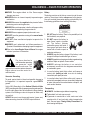
DCA-45SSIU2 — RULES FOR SAFE OPERATION
■
Backfeed to a utility system can cause
electrocution
and or
property damage. DO NOT connect to any building's electrical
system except through an approved device or after building
main switch is opened. ALWAYS have a licensed electrician
perform the installation
CAUTIONCAUTION
CAUTIONCAUTION
CAUTION
:
DO NOT touch or open any of the below
mentioned components while the
generator is running. Always allow
sufficient time for the engine and generator
to cool before performing maintenance.
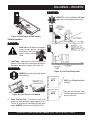
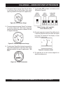
Radiator
1. Radiator Cap - Removing the radiator cap while the engine
is hot will result in high pressurized, boiling water to gush
out of the radiator, causing severe scalding to any persons
in the general area of the generator.
2. Coolant Drain Plug - Removing the coolant drain plug
while the engine is hot will result in hot coolant to gush out
of the coolant drain plug, therefore causing severe scalding
to any persons in the general area of the generator.
3. Engine Oil Drain Plug - Removing the engine oil drain
plug while the engine is hot will result in hot oil to gush out
of the oil drain plug, therefore causing severe scalding to
any persons in the general area of the generator.
DANGERDANGER
DANGERDANGER
DANGER
:
DANGERDANGER
DANGERDANGER
DANGER
:
■
NEVER touch output terminals during operation. This is
extremely dangerous. ALWAYS stop the machine and
place the circuit breaker in the “OFF” position when contact
with the output terminals is required. There exists the
possibility of
electrocution, electrical shock or burn,
which can cause severe bodily harm or even death
!
Never use damaged or worn cables when
connecting equipment to the generator.
Make sure power
connecting
cables are
securely connected to the
generator’s output terminals,
insufficient tightening of the
terminal connections may cause
damage to the generator and
electrical shock.
.
Maintenance Safety
■
NEVER lubricate components or attempt service on a running
machine.
■
ALWAYS allow the machine a proper
amount of time to cool before servicing.
■
Keep the machinery in proper running condition.
■
Fix damage to the machine immediately and always replace
broken parts.
■
ALWAYS make sure that electrical circuits are properly
grounded
per the
National Electrical Code
(NEC) and local
codes before operating generator. Severe
injury
or
death!
by
electrocution can result from operating an ungrounded
generator.
■
ALWAYS be sure the operator is familiar with proper safety
precautions and operations techniques before using generator.
■
ALWAYS store equipment properly when it is not being used.
Equipment should be stored in a clean, dry location out of the
reach of children.
■
ALWAYS read, understand, and follow
procedures in Operator’s Manual before
attempting to operate equipment.
DANGERDANGER
DANGERDANGER
DANGER
:
DANGERDANGER
DANGERDANGER
DANGER
:
POWER
CORD
(POWER ON)
WET
HANDS
NEVER grab or
touch a live
power cord with
wet hands , the
possibility exists
of electrical shock, electrocution, and even
death!

PAGE 14 — DCA-45SSIU2 — OPERATION AND PARTS MANUAL (STD) — REV. #7 (06/13/07)
DCA-45SSIU2 — RULES FOR SAFE OPERATION
■
NEVER Run engine without air filter. Severe engine
damage may occur.
■
ALWAYSservice air cleaner frequently to prevent engine
malfunction.
■
ALWAYS disconnect the
negative battery terminal
before
performing service on the generator.
■
ALWAYS be sure the operator is familiar with proper safety
precautions when operating the generator set.
■
ALWAYS store equipment properly when not in use.
■
DO NOT leave the generator running in the
manual mode
unattended.
■
DO NOT allow unauthorized people to operate this
equipment.
■
ALWAYS read, understand, and follow procedures in
Operator’s Manual before attempting to operate equipment.
■
Refer to the
Isuzu Engine Owner's Manual
for engine
technical questions or information.
Battery
The battery contains acids that can cause injury to the eyes
and skin. To avoid eye irritation,
always
wear safety glasses.
Use well insulated gloves when picking up the battery. Use
the following guidelines when handling the battery:
1. DO NOT drop the battery. There is the possibility of risk
that the battery may explode.
2. DO NOT expose the battery to
open flames, sparks, cigarettes
etc. The battery contains
combustible gases and liquids. If
these gases and liquids come in
contact with a flame or spark, an
explosion could occur.
3. ALWAYS keep the battery charged. If the battery is not
charged a buildup of combustible gas will occur.
4. ALWAYS keep battery charging and cables in good working
condition. Repair or replace all worn cables.
5. ALWAYS recharge the battery in an vented air
environment, to avoid risk of a dangerous concentration
of combustible gases.
6. In case the battery liquid (dilute sulfuric acid) comes in
contact with
clothing or skin
, rinse skin or clothing
immediately with plenty of water.
7. In case the battery liquid (dilute sulfuric acid) comes in
contact with your eyes, rinse eyes immediately with plenty
of water, then contact the nearest doctor or hospital, and
seek medical attention.
Pay close attention to
ventilation when operating
the generator inside
tunnels and caves. The
engine exhaust contains noxious elements.
Engine exhaust must be routed to a
ventilated area.
DANGER:DANGER:
DANGER:DANGER:
DANGER:
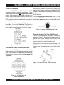
Generator Grounding
To guard against electrical shock and possible damage to
the equipment, it is important to provide a good EARTH
ground.
Article 250 (Grounding) of the
National Electrical Code
(NEC) provides guide lines for proper grounding and specifies
that the cable ground shall be connected to the grounding
system of the building as close to the point of cable entry
as practical.
ALWAYS be sure to use the ground terminal (green wire)
when connecting a load to the UVWO output terminals.
Transporting
■
ALWAYS shutdown engine before transporting.
■
Tighten both fuel tank caps securely.
■
If generator is mounted on a trailer, make sure trailer
complies with all local and state safety transportation
laws. See next page “
Towing Safety Precautions
” for
basic towing techniques.

DCA-45SSIU2 — OPERATION AND PARTS MANUAL (STD) — REV. #7 (06/13/07) — PAGE 15
Emergencies
■
ALWAYS know the location of the nearest
fire extinguisher
.
■
ALWAYS know the location of the nearest and
first aid kit
.
■
In emergencies
always
know the location of the
nearest phone or
keep a phone on the job site
.
Also know the phone numbers of the nearest
ambulance
,
doctor
and
fire department
. This
information will be invaluable in the case of an
emergency.
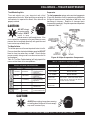
To reduce the possibility of an accident while transporting
the generator on public roads, always make sure the trailer
that supports the generator and the towing vehicle are in
good operating condition and both units are mechanically
sound.
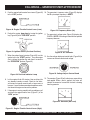
The following list of suggestions should be used when towing
your generator:
■
Make sure the hitch and coupling of the towing vehicle
are rated equal to, or greater than the trailer "gross vehicle
weight rating" (GVWR) of 6,000 lbs.
■
ALWAYS inspect the hitch and coupling for wear. NEVER
tow a trailer with defective hitches, couplings, chains
etc.
■
Check the tire air pressure on both towing vehicle and
trailer.
Trailer tires should be inflated to 50 psi cold.
Also check the tire tread wear on both vehicles.
■
ALWAYS make sure the trailer is equipped with a "Safety
Chain".
■
ALWAYS attach trailer’s safety chains to towing vehicle
properly.
■
ALWAYS make sure the vehicle and trailer directional,
backup, brake, and trailer lights are connected and
working properly.
■
The maximum speed for highway towing is 45 MPH
unless posted otherwise. Recommended off-road towing
is not to exceed 10 MPH or less depending on type of
terrain.
■
Place
chock blocks
underneath wheel to prevent rolling,
while parked.
■
Use the trailer’s swivel jack to adjust the trailer height to
a level position while parked.
■
Avoid sudden stops and starts. This can cause skidding,
or jack-knifing. Smooth, gradual starts and stops will
improve towing.
Towing Safety Precautions
CAUTION:CAUTION:
CAUTION:CAUTION:
CAUTION:
Conform to
Department of Transportation
(DOT)
Safety Towing Regulations
before
towing generator.
■
Avoid sharp turns.
■
Trailer should be adjusted to a level position at all times
when towing.
■
Raise and lock trailer wheel stand in up position when
transporting.
■
DOT Requirements include the following:
DCA-45SSIU2 — RULES FOR SAFE OPERATION
z
Connect and test electric brake operation.
z
Secure portable power cables in cable tray with
tie wraps.

PAGE 16 — DCA-45SSIU2 — OPERATION AND PARTS MANUAL (STD) — REV. #7 (06/13/07)
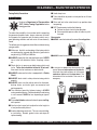
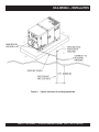
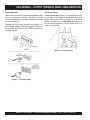
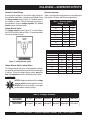
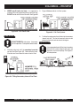
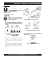
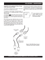
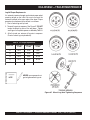
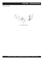
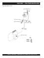
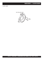
Figure 3. Typical Generator Grounding Application
DCA-45SSIU2 — INSTALLATION

DCA-45SSIU2 — OPERATION AND PARTS MANUAL (STD) — REV. #7 (06/13/07) — PAGE 17
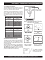
Outdoor Installation
Install the generator in a clear area. Make sure the generator
is on secure level ground so that it cannot slide or shift
around. Also install the generator in a manner so that the
exhaust will not be discharged in the direction of nearby
homes.
The installation site must be relatively free from moisture
and dust. All electrical equipment should be protected from
excessive moisture. Failure to do will result in deterioration
of the insulation and will result in short circuits and grounding.
Foreign materials such as dust, sand, lint and abrasive
materials have a tendency to cause excessive wear to
engine and alternator parts.
CAUTIONCAUTION
CAUTIONCAUTION
CAUTION
:
Pay close attention to ventilation when
operating the generator inside tunnels and
caves. The engine exhaust contains
noxious elements. Engine exhaust must be
routed to a ventilated area.
Indoor Installation
Exhaust gases from diesel engines are extremely poisonous.
Whenever an engine is installed indoors the exhaust fumes
must be vented to the outside. The engine should be installed
at least two feet from any outside wall. Using an exhaust
pipe which is too long or too small can cause excessive
back pressure which will cause the engine to heat
excessively and possibly burn the valves.
Mounting
The generator must be mounted on a solid foundation (such
as concrete) and set firmly on the foundation to isolate
vibration of the generator when it is running. The generator
must set at least 6 inches above the floor or grade level (in
accordance to NFPA 110, Chapter 5-4.1). DO NOT remove
the metal skids on the bottom of the generator. They are to
resist damage to the bottom of the generator and to maintain
alignment.
Generator Grounding
To guard against electrical shock and possible damage to
the equipment, it is important to provide a good EARTH
ground.
Article 250 (Grounding) of the National Electrical Code (NEC)
provides guide lines for proper grounding and specifies that
the cable ground shall be connected to the grounding system
of the building as close to the point of cable entry as
practical.
NEC articles 250-64(b) and 250-66 set the following
grounding requirements:
1. Use one of the following wire types to connect the
generator to earth ground.
a. Copper - 10 AWG (5.3 mm
2
) or larger.
b. Aluminum - 8 AWG (8.4 mm
2
) or larger.
2. When grounding the generator (Figure 3) connect the
ground cable between the lock washer and the nut on
the generator and tighten the nut fully. Connect the other
end of the ground cable to earth ground.
3. NEC article 250-52(c) specifies that the earth ground
rod should be buried aminimum of 8 ft. into the ground.
When connecting the generator to
any buildings electrical system
ALWAYS consult with a licensed
electrician.
DCA-45SSIU2 — INSTALLATION
NOTE

PAGE 18 — DCA-45SSIU2 — OPERATION AND PARTS MANUAL (STD) — REV. #7 (06/13/07)
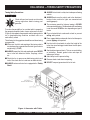
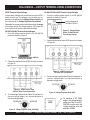
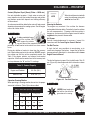
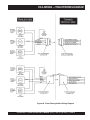
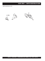
To reduce the possibility of an accident while transporting
the generator on public roads, always make sure the trailer
(Figure 4) that supports the generator and the towing vehicle
are in good operating condition and both units are
mechanically sound.
The following list of suggestions should be used when towing
your generator:
CAUTIONCAUTION
CAUTIONCAUTION
CAUTION
:
Towing Safety Precautions
Check with your local county or state safety
towing regulations before towing your
generator.
■
Make sure the hitch and coupling of the towing vehicle
are rated equal to, or greater than the trailer "gross vehicle
weight rating" (GVWR).
■
ALWAYS inspect the hitch and coupling for wear. NEVER
tow a trailer with defective hitches, couplings, chains
etc.
■
Check the tire air pressure on both towing vehicle and
trailer. Also check the tire tread wear on both vehicles.
■
ALWAYS make sure the trailer is equipped with a "Safety
Chain".
DCA-45SSIU2 — TOWING SAFETY PRECAUTIONS
■
ALWAYS attach trailer’s safety chain to bumper of towing
vehicle.
■
ALWAYS make sure the vehicle and trailer directional,
backup, brake, and trailer lights are connected and
working properly.
■
The maximum speed for highway towing is 55 MPH
unless posted otherwise. Recommended off-road towing
is not to exceed 15 MPH or less depending on type of
terrain.
■
Place
chocked blocks
underneath wheel to prevent
rolling, while parked.
■
Place
support blocks
underneath the trailer’s bumper to
prevent tipping, while parked.
■
Use the trailer’s hand winch to adjust the height of the
trailer, then insert locking pin to lock wheel stand in place,
while parked.
■
Avoid sudden stops and starts. This can cause skidding,
or jackknifing. Smooth, gradual starts and stops will
improve gas milage.
■
Avoid sharp turns to prevent rolling.
■
Remove wheel stand when transporting.
■
DO NOT transport generator with fuel in tank.
Figure 4. Generator with Trailer

DCA-45SSIU2 — OPERATION AND PARTS MANUAL (STD) — REV. #7 (06/13/07) — PAGE 19
Explanation of Chart:
This section is to provide the user with trailer service and
maintenance information. The service and maintenance
guidelines referenced in this section apply a wide range of
trailers. Remember periodic inspection of the trailer will en-
sure safe towing of the equipment and will prevent damage
to the equipment and personal injury.
It is the purpose of this section to cover the major mainte-
nance components of the trailer. The following trailer com-
ponents will be discussed in this section:
Brakes
Tires
Lug Nut Torquing
Suspension
Electrical
Brake Troubleshooting Tables
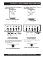
Use the following definitions when reading Table 2.
1. Fuel Cell - Provides an adequate amount of fuel for the
equipment in use. Fuel cells must be empty when trans-
porting equipment.
2. Braking System - System employed in stopping the
trailer. Typical braking systems are electric, surge, hy-
draulic, hydraulic-surge and air.
3. GVWR- Gross Vehicle Weight Rating (GVWR), is the
maximum number of pounds the trailer can carry, in-
cluding the fuel cell (empty).
4. Frame Length - Measurement is from the ball hitch to
the rear bumper (reflector).
DCA-45SSIU2 — TRAILER SPECIFICATIONS
CAUTIONCAUTION
CAUTIONCAUTION
CAUTION
:
ALWAYS make sure the trailer is in good
operating condition. Check the tires for
proper inflation and wear. Also check the
wheel lug nuts for proper tightness.
5. Frame Length - Measurement is from fender to fender
6. Jack Stand - Trailer support device with maximum pound
requirement from the tongue of the trailer.
7. Coupler - Type of hitch used on the trailer for towing.
8. Tire Size - Indicates the diameter of the tire in inches
(10,12,14, etc.), and the width in millimeters
(175,185,205, etc.). The tire diameter must match the
diameter of the tire rim.
9. Tire Ply - The tire ply (layers) number is rated in letters;
2-ply,4-ply,6-ply, etc.
10. Wheel Hub - The wheel hub is connected to the trailer’s
axle.
11. Tire Rim - Tires mounted on a tire rim. The tire rim must
match the size of the tire.
12. Lug Nuts - Used to secure the wheel to the wheel hub.
Always use a torque wrench to tighten down the lug nuts.
See Table 17 and Figure 67
or lug nut tightening and
sequence.
13. Axle - Indicates the maximum weight the axle can sup-
port in pounds, and the diameter of the axle expressed
in inches (see Table 2). Please note that some trailers
have a double axle. This will be shown as 2-6000 lbs.,
meaning two axles with a total weight capacity of 6000
pounds.
14. Suspension - Protects the trailer chassis from shocks
transmitted through the wheels. Types of suspension used
are leaf, Q-flex, and air ride.
15. Electrical - Electrical connectors (looms) are provided
with the trailer so the brake lights and turn signals can
be connected to the towing vehicle.
16. Application - Indicates which units can be employed
on a particular trailer.

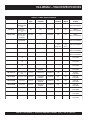
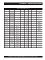
PAGE 20 — DCA-45SSIU2 — OPERATION AND PARTS MANUAL (STD) — REV. #7 (06/13/07)
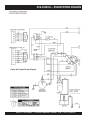
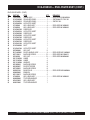
DCA-45SSIU2 — TRAILER SPECIFICATIONS
snoitacificepSreliarT.2elbaT
LEDOM NOITACILPPA LEUF
LLEC
EKARB
METSYS
RWVG EMARF
HTGNEL
EMARF
HTDIW
KCAJ
DNATS
W01-RLRT ,522WDS
-WLT,052WGS
003
ONONSBL0091"69"05.BL008
LEEHWTLITLLUF
01-RLRT ,01ACD
-ACD,21GLT
51
ONONSBL00
91"69"05.BL008
LEEHWTLITLLUF
FX01-RLRT -GLT,01ACD
,51ACD,21
003-WLT
LAG25ONSBL0091"69"05.BL008
LEEHWTLITLLUF
W522-RLR
T ,SREDLEW
SS0007AD
ONONSBL0022"58"24.BL008
LEEHWTLITLLUF
004WLB-RLRT 004-WLBONCIRTCELESBL0072TSAM/W
"451
"421O/W
"55
"8
7(
)LLAT
.BL008
LEEHWTLITLLUF
X05-RLRT 52-ACDONONSBL0072"421"55.BL008
LEEHWTLITLLUF
FX05-RLRT 52-ACDLAG14ONSBL0072"421"5
5.BL008
LEEHWTLITLLUF
W07-RLRT ,06-,54-ACD
07
ONEGRUSSBL0007"681"77.BL0002
DAPTALF
X07-RLRT ,06-,54-ACD
07
TPOEGRUSSBL0
007"831"66.BL0002
DAPTALF
FX07-RLRT ,06-,54-ACD
07
LAG35EGRUSSBL0007"831"66.BL0002
DAPTALF
FX001-RLRT 521,001-ACDLAG05
1CILUARDYH
EGRUS
SBL0007"091"67.BL0002
DAPTALF
521/58-RLRT ,001,58-ACD
521
LAG541CILUARDYHSBL00001"681"77.BL0002
DAPTA
LF
FX051-RLRT 081,051-ACDLAG002CILUARDYH
EGRUS
SBL06111"402"48.BL0005
DAPTALF
FX022-RLRT 022-ACDLAG052CILUARDYH
EGRU
S
SBL00041"222"38.BL0005
DAPTALF
FX003-RLRT 003-ACDLAG052CILUARDYH
EGRUS
SBL00081"832"38.BL0005
DAPTALF
FX004-RLRT 004
-ACDLAG053CIRTCELESBL00081"832"38.BL0005
DAPTALF
FX006-RLRT 008,006-ACDLAG055RIASBL00003"483"69.BL0005
DAPTALF
XS008-R
LRT 008,006-ACDLAG055RIASBL00003"483"69.BL0005
DAPTALF
Page is loading ...
Page is loading ...
Page is loading ...
Page is loading ...
Page is loading ...
Page is loading ...
Page is loading ...
Page is loading ...
Page is loading ...
Page is loading ...
Page is loading ...
Page is loading ...
Page is loading ...
Page is loading ...
Page is loading ...
Page is loading ...
Page is loading ...
Page is loading ...
Page is loading ...
Page is loading ...
Page is loading ...
Page is loading ...
Page is loading ...
Page is loading ...
Page is loading ...
Page is loading ...
Page is loading ...
Page is loading ...
Page is loading ...
Page is loading ...
Page is loading ...
Page is loading ...
Page is loading ...
Page is loading ...
Page is loading ...
Page is loading ...
Page is loading ...
Page is loading ...
Page is loading ...
Page is loading ...
Page is loading ...
Page is loading ...
Page is loading ...
Page is loading ...
Page is loading ...
Page is loading ...
Page is loading ...
Page is loading ...
Page is loading ...
Page is loading ...
Page is loading ...
Page is loading ...
Page is loading ...
Page is loading ...
Page is loading ...
Page is loading ...
Page is loading ...
Page is loading ...
Page is loading ...
Page is loading ...
Page is loading ...
Page is loading ...
Page is loading ...
Page is loading ...
Page is loading ...
Page is loading ...
Page is loading ...
Page is loading ...
Page is loading ...
Page is loading ...
Page is loading ...
Page is loading ...
Page is loading ...
Page is loading ...
Page is loading ...
Page is loading ...
Page is loading ...
Page is loading ...
Page is loading ...
Page is loading ...
Page is loading ...
Page is loading ...
Page is loading ...
Page is loading ...
Page is loading ...
Page is loading ...
Page is loading ...
Page is loading ...
Page is loading ...
Page is loading ...
Page is loading ...
Page is loading ...
Page is loading ...
Page is loading ...
Page is loading ...
Page is loading ...
Page is loading ...
Page is loading ...
Page is loading ...
Page is loading ...
Page is loading ...
Page is loading ...
Page is loading ...
Page is loading ...
Page is loading ...
Page is loading ...
Page is loading ...
Page is loading ...
Page is loading ...
Page is loading ...
Page is loading ...
Page is loading ...
Page is loading ...
Page is loading ...
Page is loading ...
Page is loading ...
Page is loading ...
Page is loading ...
Page is loading ...
Page is loading ...
Page is loading ...
Page is loading ...
Page is loading ...
Page is loading ...
Page is loading ...
Page is loading ...
Page is loading ...
Page is loading ...
Page is loading ...
Page is loading ...
Page is loading ...
Page is loading ...
Page is loading ...
Page is loading ...
Page is loading ...
Page is loading ...
Page is loading ...
Page is loading ...
Page is loading ...
Page is loading ...
-
 1
1
-
 2
2
-
 3
3
-
 4
4
-
 5
5
-
 6
6
-
 7
7
-
 8
8
-
 9
9
-
 10
10
-
 11
11
-
 12
12
-
 13
13
-
 14
14
-
 15
15
-
 16
16
-
 17
17
-
 18
18
-
 19
19
-
 20
20
-
 21
21
-
 22
22
-
 23
23
-
 24
24
-
 25
25
-
 26
26
-
 27
27
-
 28
28
-
 29
29
-
 30
30
-
 31
31
-
 32
32
-
 33
33
-
 34
34
-
 35
35
-
 36
36
-
 37
37
-
 38
38
-
 39
39
-
 40
40
-
 41
41
-
 42
42
-
 43
43
-
 44
44
-
 45
45
-
 46
46
-
 47
47
-
 48
48
-
 49
49
-
 50
50
-
 51
51
-
 52
52
-
 53
53
-
 54
54
-
 55
55
-
 56
56
-
 57
57
-
 58
58
-
 59
59
-
 60
60
-
 61
61
-
 62
62
-
 63
63
-
 64
64
-
 65
65
-
 66
66
-
 67
67
-
 68
68
-
 69
69
-
 70
70
-
 71
71
-
 72
72
-
 73
73
-
 74
74
-
 75
75
-
 76
76
-
 77
77
-
 78
78
-
 79
79
-
 80
80
-
 81
81
-
 82
82
-
 83
83
-
 84
84
-
 85
85
-
 86
86
-
 87
87
-
 88
88
-
 89
89
-
 90
90
-
 91
91
-
 92
92
-
 93
93
-
 94
94
-
 95
95
-
 96
96
-
 97
97
-
 98
98
-
 99
99
-
 100
100
-
 101
101
-
 102
102
-
 103
103
-
 104
104
-
 105
105
-
 106
106
-
 107
107
-
 108
108
-
 109
109
-
 110
110
-
 111
111
-
 112
112
-
 113
113
-
 114
114
-
 115
115
-
 116
116
-
 117
117
-
 118
118
-
 119
119
-
 120
120
-
 121
121
-
 122
122
-
 123
123
-
 124
124
-
 125
125
-
 126
126
-
 127
127
-
 128
128
-
 129
129
-
 130
130
-
 131
131
-
 132
132
-
 133
133
-
 134
134
-
 135
135
-
 136
136
-
 137
137
-
 138
138
-
 139
139
-
 140
140
-
 141
141
-
 142
142
-
 143
143
-
 144
144
-
 145
145
-
 146
146
-
 147
147
-
 148
148
-
 149
149
-
 150
150
-
 151
151
-
 152
152
-
 153
153
-
 154
154
-
 155
155
-
 156
156
-
 157
157
-
 158
158
-
 159
159
-
 160
160


MQ Power DCA-45USI Specification
- Category
- Trash Compactor
- Type
- Specification
- This manual is also suitable for
Ask a question and I''ll find the answer in the document
Finding information in a document is now easier with AI
Related papers
-
 MULTIQUIP Whisperwatt DCA150USJ2 Specification
-
 MULTIQUIP Whisperwatt DCA150USJ2 Specification
-
 MULTIQUIP DCA-45USI User manual
-
MQ Power DCA25SSI2 Operating instructions
-
 MULTIQUIP DCA25SSAI User manual
-
 MULTIQUIP DCA-40SSAI User manual
-
-
 MULTIQUIP DCA70SSIU2 User manual
-
 MULTIQUIP DCA-180SSV User manual
-
 MULTIQUIP DCA-180SSV User manual


Other documents
-
FSR FL-400-SLD-ALU-C Installation guide
-
 MULTIQUIP DCA-600SSV User manual
-
 MULTIQUIP DCA-25USI2XF User manual
-
 MQ Multiquip MLT-SERIES Operating instructions
-
AEV Front Bumper & Skid Plate Light Harness Installation guide
-
 MQ Multiquip SGW-250SS User manual
-
Smith Blair Inc 24500066306000 Installation guide
-
Toro Block Heater Kit, RT1200 Trencher Installation guide
-
 MQ Multiquip BLW400SSW User manual
-
Generac Power Systems 0D9727 User manual


