Page is loading ...

Algo Communication Products Ltd. 4500 Beedie Street, Burnaby, B.C. Canada V5J 5L2
Tel: (604) 438-3333 Fax: (604) 437-5726 www.algosolutions.com
Algo Communication Products Ltd. 4500 Beedie Street, Burnaby, B.C. Canada V5J 5L2
Tel: (604) 438-3333 Fax: (604) 437-5726 www.algosolutions.com
P. 1
ABOUT THE 3006 DOORPHONE
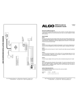
The Algo Doorphone Model 3006 consists of a control unit (3005), a door station
(3004) and a power supply (3242). All options and controls are factory set to allow
for a quick installation of simple wire connections.
QUICK INSTALL
STEP 1
Run a two-pair cable from the door station location to the control unit location
(equipment room). A recessed double-gang utility box is ideal for mounting the
door station. The door station can be located anywhere a speakerphone or talkback
paging would be considered. The door station should be mounted at shoulder
height.
STEP 2
Connect the door station as per the wiring diagram on page 4. Use this wiring
configuration as a standard so that all installations are similar. Mount the door
station, dressing all wires neatly.
STEP 3
Wall mount the control unit as near as possible to an AC outlet. Connect the door
station wires as per the attached drawing.
STEP 4
Connect the control unit terminals (T & R) to a CO line or trunk circuit of the
telephone system. The control unit will also work with single line telephones.
STEP 5
Connect the power adapter into the rear of the circuit unit cabinet and plug into an
AC outlet.
STEP 6
Test the unit by pushing the call button of the door station. The control unit initiates
ringing into the telephone system. Answer the “call” and ensure that a voice path is
established with the door station.
NOTE: The Doorphone is factory set to ring five times and then abandon the
call. This may be changed by setting the “ring persist” option switches.
3006 Trunk Port Doorphone Installation Guide
DC300600-05
Jul 02, 2002.
P.4

Algo Communication Products Ltd. 4500 Beedie Street, Burnaby, B.C. Canada V5J 5L2
Tel: (604) 438-3333 Fax: (604) 437-5726 www.algosolutions.com
Algo Communication Products Ltd. 4500 Beedie Street, Burnaby, B.C. Canada V5J 5L2
Tel: (604) 438-3333 Fax: (604) 437-5726 www.algosolutions.com
P.2
Ring Enable/Disable
Controlled by SWITCH-2, position 8 on the bottom of the control unit. In the ON
position (factory setting), ring voltage is provided at the “T & R” following the se-
lected cadence. In the OFF position, only the auxiliary relay is operated.
Speaker Volume
This is adjusted by a knob at the rear of the control unit. Turn knob clockwise to
increase volume.
MICROPHONE SENSITIVITY
This control is not normally field adjusted. Screwdriver adjustment is
possible, however, to bias the switching circuit to favor one direction. Factory
setting is 1/4 turn clockwise from a full counter-clockwise (OFF) position. Field
adjustment should consist of a minimal turn in one direction or the other. Over
adjustment will impair the switching function. Should this occur return adjustment
to original factory position.
RELAY TERMINALS
In some cases it will be desirable to use an auxiliary ringer in place of or in
conjunction with ringing the telephone system. These terminals will always
follow the ring cadence and ring persist selections. Ringing to the telephone
system may be turned off by setting position 8 of SWITCH-2 to OFF.
AUXILIARY JACK
This jack provides power and signal lines to operate the Algo Model 3106 Door
Control Module. Do NOT use this jack for anything else. The 3106 Door Control
Module will provide a dry contact closure to operate a customer-supplied door
latch. The relay is sufficiently rated for most low-voltage solenoids currently avail-
able. Consult the 3106 installation instructions for details of operation and switch
selections.
REPAIRS
It is not recommended that this product be repaired in the field. Should the product
require repair, return to Algo using standard repair return procedures. A return
authorization number must be obtained before returning any product to Algo.
Call Algo Communication Products Ltd. customer service at (604) 438-3333 to
obtain a return authorization number and additional product information.
P.3
SWITCH OPTIONS AND CONTROL
The installer may change the following features:
?
Ring Cadence
?
Ring Persistence
?
Ring Disable
?
Speaker Volume
Ring Cadence
Controlled by SWITCH-1 on the bottom of the control unit. The eight positions of
this switch are scanned during each ring cycle from position 1 through 8.
Each switch that is on will contribute to the ring period. Each switch represents
approximately 0.5 seconds of the ring cycle. A 0.5 second interval follows after
each switch scan to give a total cycle of 4.5 seconds. The factory setting provides
a 1.5 sec. ON followed by a 3 sec. OFF cadence. Factory setting is as follows:
SWITCH-1 X = ON O = OFF
POSITION: 1 2 3 4 5 6 7 8
X X X O O O O O
----ON---- ----------OFF------
Numerous cadences are possible, and can be chosen to distinguish the
Doorphone from outside calls and ring messaging.
Ring Persist
Controlled by SWITCH-2 on the bottom of the control unit. This determines the
number of ring cycles that will ensue each call if left unanswered. The factory
setting is for five rings. Position 8 enables ring voltage (see Ring Enable on p 3).
SWITCH-2 X = ON O = OFF - = don’t care
POSITON: 1 2 3 4 5 6 7
X - - - - - - No ring
O X - - - - - One ring
O O X - - - - Two rings
O O O X - - - Three rings
O O O O X - - Four rings
O O O O O X - Five rings
O O O O O O X Six rings
O O O O O O O No limit
POSITON: 8
X Ring Voltage
O Auxiliary Relay

Algo Communication Products Ltd. 4500 Beedie Street, Burnaby, B.C. Canada V5J 5L2
Tel: (604) 438-3333 Fax: (604) 437-5726 www.algosolutions.com
Algo Communication Products Ltd. 4500 Beedie Street, Burnaby, B.C. Canada V5J 5L2
Tel: (604) 438-3333 Fax: (604) 437-5726 www.algosolutions.com
P.2
Ring Enable/Disable
Controlled by SWITCH-2, position 8 on the bottom of the control unit. In the ON
position (factory setting), ring voltage is provided at the “T & R” following the se-
lected cadence. In the OFF position, only the auxiliary relay is operated.
Speaker Volume
This is adjusted by a knob at the rear of the control unit. Turn knob clockwise to
increase volume.
MICROPHONE SENSITIVITY
This control is not normally field adjusted. Screwdriver adjustment is
possible, however, to bias the switching circuit to favor one direction. Factory
setting is 1/4 turn clockwise from a full counter-clockwise (OFF) position. Field
adjustment should consist of a minimal turn in one direction or the other. Over
adjustment will impair the switching function. Should this occur return adjustment
to original factory position.
RELAY TERMINALS
In some cases it will be desirable to use an auxiliary ringer in place of or in
conjunction with ringing the telephone system. These terminals will always
follow the ring cadence and ring persist selections. Ringing to the telephone
system may be turned off by setting position 8 of SWITCH-2 to OFF.
AUXILIARY JACK
This jack provides power and signal lines to operate the Algo Model 3106 Door
Control Module. Do NOT use this jack for anything else. The 3106 Door Control
Module will provide a dry contact closure to operate a customer-supplied door
latch. The relay is sufficiently rated for most low-voltage solenoids currently avail-
able. Consult the 3106 installation instructions for details of operation and switch
selections.
REPAIRS
It is not recommended that this product be repaired in the field. Should the product
require repair, return to Algo using standard repair return procedures. A return
authorization number must be obtained before returning any product to Algo.
Call Algo Communication Products Ltd. customer service at (604) 438-3333 to
obtain a return authorization number and additional product information.
P.3
SWITCH OPTIONS AND CONTROL
The installer may change the following features:
?
Ring Cadence
?
Ring Persistence
?
Ring Disable
?
Speaker Volume
Ring Cadence
Controlled by SWITCH-1 on the bottom of the control unit. The eight positions of
this switch are scanned during each ring cycle from position 1 through 8.
Each switch that is on will contribute to the ring period. Each switch represents
approximately 0.5 seconds of the ring cycle. A 0.5 second interval follows after
each switch scan to give a total cycle of 4.5 seconds. The factory setting provides
a 1.5 sec. ON followed by a 3 sec. OFF cadence. Factory setting is as follows:
SWITCH-1 X = ON O = OFF
POSITION: 1 2 3 4 5 6 7 8
X X X O O O O O
----ON---- ----------OFF------
Numerous cadences are possible, and can be chosen to distinguish the
Doorphone from outside calls and ring messaging.
Ring Persist
Controlled by SWITCH-2 on the bottom of the control unit. This determines the
number of ring cycles that will ensue each call if left unanswered. The factory
setting is for five rings. Position 8 enables ring voltage (see Ring Enable on p 3).
SWITCH-2 X = ON O = OFF - = don’t care
POSITON: 1 2 3 4 5 6 7
X - - - - - - No ring
O X - - - - - One ring
O O X - - - - Two rings
O O O X - - - Three rings
O O O O X - - Four rings
O O O O O X - Five rings
O O O O O O X Six rings
O O O O O O O No limit
POSITON: 8
X Ring Voltage
O Auxiliary Relay

/