Page is loading ...

Save this manual for future reference.
For more information, visit www.desatech.com
GA9050A-1 SERIES
MANUAL ON/OFF SAFETY VALVE/PILOT KIT
For All Single, Dual and Triple Burner
Natural and Propane/LP Gas Logs
WARNING: If the information in this manual is not
-
—
-
-
The GA9050A-1 Series Manual On/Off Safety Valve/Pilot kit contains the following:
• PiezoIgnitor 097159-04
• ManualValve 901068-02
• PilotBurner(withnatural
gasorice) 901069-01
• PiezoIgnitorElectrode 901072-01
• SteelShroud-PilotKit 901139-01
• PilotKitIncidentals 901152-01
• ControlDialInstructions 901042-01
• Brass3/8FLRx3/8MPTElbow 14264
• 18"Propane/LPBrassOrice 901065-02
• 24"Propane/LPBrassOrice 901065-03
• 30"Propane/LPBrassOrice 901065-04
• Propane/LPBrassAirMixer 901066-02
• Propane/LPPilotBurnerOrice901070-01
• Screw1/4"#8“B”pt(4ea.) 901075-01
• PilotValveControlDial 901079-01
• PilotValveDialExtension3" 901080-01
• PropaneConversionDecal 901691-01

www.desatech.com
901054-01M2
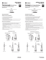
MODEL DESCRIPTION
Natural Gas
B
Minimum Vent
(C,V,F,B)VSR18 18"SingleBurner 50,000 40,000 8"dia.
(C,V,F,B)VSR24 24"SingleBurner 60,000 50,000 8"dia.
CPVSR18 18"SingleBurner 50,000 40,000 8"dia.
CPVSR24 24"SingleBurner 60,000 50,000 8"dia.
(C,HC,V,F,B)VDR18 18"DualBurner 55,000 45,000 8"dia.
(C,HC,V,F,B)VDR24 24"DualBurner 65,000 55,000 8"dia.
(C,V,F,B)VDR30 30"DualBurner 70,000 60,000 8"dia.
(C)BFL(T,R)18 18"TripleBurner 65,000 55,000 8"dia.
(C)BFL(T,R)24 24"TripleBurner 70,000 60,000 8"dia.
*Add6"ifsafetyvalve/pilotisused
**Atdepthindicated
Gas Min. Max.
NG 5.5" 10.5"
LP 11" 13"
PROPANE/LP
LOG SIZE
18SR/DR 0.120 31 Blue 0.073 49 Red
24SR/DR/BFL18 0.129 30 Green 0.086 44
Orange
30DR/BFL24 0.1405 28 Yellow 0.089 43 Black
INSTALLATION
MODEL
WIDTH*
BACK
WIDTH**
DEPTH HEIGHT
18DR/SR 28" 16" 14" 18"
24DR/SR 29
3
/
4
" 17" 15
1
/
2
" 18"
30DR 36" 27" 18" 18"
BFL18 28" 16" 15
1
/
2
" 18"
BFL24 30" 22" 15
1
/
2
" 18"
Figure 1 - Technical Information Charts

www.desatech.com
901054-01M 3
CHECK GAS TYPE
YoumustinstallthisON/OFFSafetyValve/
PilotKitifyourgastypeispropane/LP.Forad-
ditionalconvenienceandsafety,thisON/OFF
SafetyValve/PilotKitcanbeusedwithnatural
gas.Ifyouareunsureoftheproperapplica-
tion,calldealerwhereyouboughtlogset.
Ifthereplacedoesnothaveagassupply
shutoffvalve,onemustbeinstalled.
-
the external regulator between the
Installation Items Needed
Beforeinstallinglogset,makesureyouhave
theitemslistedbelow.
• piping(checklocalcodes)
• sealant(resistanttopropane/LPgas)
• equipmentshutoffvalve*
• testgaugeconnection*
• adjustable(crescent)wrenchorpliers
• sedimenttrap
• teejoint
• pipewrench
• exiblegasline
• 10mmDeepSocket
*A CSA design-certied equipment shutoff
valvewith1/8"NPTtapisanacceptableal-
ternativetotestgaugeconnection.Purchase
theoptionalCSAdesign-certiedequipment
shutoffvalvefromyourdealer.
INSTALLATION
Continued
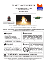
Forpropane/LPunits,theinstallermustsupply
anexternalregulator.Theexternalregulator
willreduceincominggaspressure.Youmust
reduceincominggaspressuretobetween11"
and14"ofwater.Ifyoudonotreduceincom-
inggaspressure, heater regulator damage
could occur. Install external regulator with
theventpointingdownasshowninFigure2.
Pointingtheventdownprotectsitfromfreez-
ingrainorsleet.
WARNING: Never connect
gas is commonly known as
-
1/2" diameter or greater to allow
Installationmustincludeanequipmentshut-
offvalve,union,andplugged1/8"NPTtap.
LocateNPTtapwithinreachfortestgauge
hookup.NPTtapmustbeupstreamfromlog
set(seeFigure3,page4).
IMPORTANT:Installequipmentshutoffvalve
in an accessible location.Theequipment
shutoff valve is for turning on or shutting off
thegastotheappliance.
Figure 2 - External Regulator on
Propane/LP Supply Tank with Vent
Pointing Down
ExternalRegulator
VentPointingDown
Propane/LP
SupplyTank

www.desatech.com
901054-01M4
Checkyour building codesfor any special
requirementsforlocatingequipmentshutoff
valvetoappliance.
ApplypipejointsealantlightlytomaleNPT
threads.Thiswillpreventexcesssealantfrom
goingintopipe.Excesssealantinpipecould
resultinacloggedburnerorice.
sealant that is resistant to liquid
Werecommendthatyou installa sediment
trapin supply line as shown in Figure 3.
Locatesedimenttrapwhereitiswithinreach
forcleaning.Installinpipingsystembetween
fuelsupplyandheater.Locatesedimenttrap
wheretrappedmatterisnotlikelytofreeze.
Asedimenttraptrapsmoistureandcontami-
nants.Thiskeepsthemfromgoingintologset
controls.Ifsedimenttrapisnotinstalledoris
installedwrong,logsetmaynotrunproperly.
INSTALLATION
Continued
Natural Gas
FromGasMeter
(5"W.C.**to10.5"
W.C.Pressure)
FromExternal
Regulator
(11"W.C.**to14"
W.C.Pressure)
Figure 3 - Gas Connection
*PurchasetheoptionalCSAdesign-certied
equipmentshutoffvalvefromyourdealer.
**Minimuminletpressureforpurposeofinput
adjustment.
3"Minimum
SedimentTrap(Optionalfor
Propane/LPInstallation)
CSADesign-Certied
EquipmentShutoffValve*
ApprovedFlexibleGasHose
(ifallowedbylocalcodes)
Tee Joint
PipeNipple
Cap
Figure 4 - Equipment Shutoff Valve
Open
Closed
Equipment
Shutoff Valve
CHECKING GAS CONNECTIONS
and connections for leaks after
WARNING: Never use an
-
PIPING SYSTEM
Test Pressures In Excess Of 1/2 PSIG
1. Disconnectlogsetanditsindividualequip-
mentshutoffvalvefromgassupplypiping
system.
2. Capoffopenendofgaspipewhereequip-
mentshutoffvalvewasconnected.
3. Pressurizesupplypipingsystembyeither
opening propane/LP supply tank valve
forpropane/LPgasoropeningmaingas
valve located onor neargas meterfor
naturalgas,orusingcompressedair.
4. Checkalljointsofgassupplypipingsystem.
Applynoncorrosiveleakdetectionuidto
alljoints.Bubblesformingshowaleak.
5. Correctallleaksatonce.
6. Reconnectlogsetandequipmentshutoff
valvetogassupply.Checkreconnected
ttingsforleaks.
Test Pressures Equal To or Less Than
1. Closeequipmentshutoffvalve(seeFig-
ure4).
2. Pressurizesupplypipingsystembyeither
opening propane/LPsupplytankvalve
forpropane/LPgasoropeningmaingas
valve located onor neargas meterfor
naturalgas,orusingcompressedair.

www.desatech.com
901054-01M 5
INSTALLATION
Continued
Figure 5 - Checking Gas Joints
(Natural Gas Only)
Gas Meter
EquipmentShutoffValve
Propane/LP
SupplyTank
EquipmentShutoffValve
Figure 6 - Checking Gas Joints
(Propane/LP Gas Only)
VALVE/PILOT KIT ASSEMBLY
Natural Gas Installation
1. Thread the gas control valveonto the
burner inlet tting(see Figure7). Use
threadsealantonthemalethreadsofthe
burnerinlettting.Holdthe burnerinlet
ttingwithawrenchtopreventovertight-
eningtheconnectiontotheburner.Make
surethecontrolrodisfacingthefront(see
Figure7).
BurnerInletFitting
(containingorice)
GasControl
Valve
Burner
Pan
Assembly
Figure 7 - Installing Gas Control Valve
Control
Rod
Figure 8 - Gas Control Valve with
Thermocouple and Pilot
Thermocouple
andLine
Pilotand
Line
GasControlValve
PilotFlow
Adjustment
Screw
Figure 9 - Installing Inlet Fitting and Gas
Connector Tube
GasControlValve
GasInlet
Fitting
Gas
Connector
Tube
InletOpening
3. Checkalljointsfromgasmeterfornatu-
ralgas(Figure5)orpropane/LPsupply
(Figure6)toequipmentshutoff valve.
Applynoncorrosiveleakdetectionuidto
alljoints.Bubblesformingshowaleak.
4. Correctallleaksatonce.
2. Attachthepilotgaslinetothepilotoutlet
ofthegascontrolvalveandtighten.Con-
nectthethermocoupletotherearofthe
gascontrolvalve.SeeFigure8.Donot
overtighten.Ifusingpropane/LPgas,see
Changing Pilot Orice,page6.
3. Installtheinletttingintotheinletopen-
ingofthegascontrolvalve(seeFigure
9).Usethreadsealantonthemalepipe
threads.
4. Place the burner pan assemblyin the
center of the replaceoor. Make sure
thefrontofpanfacesforward.

www.desatech.com
901054-01M6
5. Thread the gas supplyadaptor to the
replacegassupplypipe.Adjusttomost
convenientposition.
6. Installthegasconnectortubetothegas
supply adaptor. Carefullyshape tube
andattachtogasinlettting(seeFigure
9,page5).Becarefulnottocausekinks
intube.
7. Testforleaksfollowinginstructionsinyour
hearthkitowner’smanualunderthesec-
tion Testing Burner for Leaks.
8. Retightenandadjustthelocationofthegas
controlasnecessary.Thegascontrolshould
belevel,withthecontrolrodtothefront.
9. Installcovertoburnerpanusingscrews
provided.
10.Installthermocouple,pilot,andignitoronto
valvecoverasshowninFigure10.Use
theprovidedscrews.
11.Pushthecontrolrodextensionontothe
“D”shapedcontrolrodthroughthecenter
holeinthecover.
12.Installthepositiondecalandcontrolknob
making sure to align the marks with the
correctstoppositionsofthegascontrol.
Pilotpositionwillallowtheknobtopush
inabout1/2".Alignthedecalsinthepilot
position.
INSTALLATION
Continued
Piezo
Ignitor
Control
Rod
Extension
Screw
Valve
Cover
Control
Knob
Figure 10 - Installing Cover, Control
Knob, and Piezo Ignitor
Thermocouple
Ignitor
Pilot
Figure 12 - Burner Inlet Fittings with
Injectors
GAS
PROPANE/LP
Injectorfor
Natural Gas
Injectorfor
Propane/LP
Gas
Figure 11 - Remove Burner Inlet Fitting
BurnerInlet
Fittingfor
Natural Gas
WARNING: You must use a
PROPANE/LP GAS CONVERSION
Toconvert topropane/LP gas, the burner
inletttingandpilotoricemustbereplaced.
Thepropane/LPburnerinletttingissupplied
alongwiththreecolorcodedoricespre-sized
foreach sizelogset.The propane/LPpilot
oriceis also includedand can beused to
convertallsizelogsets.Youmustinstallthe
correctsizeoriceintothepropane/LPburner
ttingusinga10mmdeepsocketdriver.
1. Removethenaturalgasburnerinlettting
fromtheburnerpanassembly(seeFigure
11).DONOTremovetheoricefromthis
tting.Thepropane/LPburnerinlettting
includedinthehardwarekithas6holes
andmustbeusedtoreplacethenatural
gasinlettting(seeFigure12).
2. Besuretousethecorrectoriceforyour
appliance. The hardware kit included
withthisappliancecontainsoriceswith
acone-likeshape.Theoricesarecolor
codedforeachrespectivesizelogsetas
indicatedbymodelnumber(see Figure
1,page2).
3. Usea10mmdeepsocketornutdriver
tothreadthenewpropane/LPoriceinto
the propane/LPburnerinlettting(see
Figure12).

www.desatech.com
901054-01M 7
4. Usingthreadsealant(resistanttotheac-
tionofpropane/LPgas)onlargerendof
tting,screwtheburnerinletttingthrough
holeand intoburner manifold.Tighten
usingawrench.
5. Followsteps1through12underNatural
Gas Installation,page5.
Thepilotisprovidedwithanaturalgasorice
installed.Forpropane/LPgasyoumustremove
itandreplaceitwithanpropane/LPorice.The
hardwarekitcontainsanpropane/LPorice
witharedstripeforconvertingthepilot.
1. Gentlyloosenandremovethepilotlinecon-
nectionfromthebracket(seeFigure13).
2. Replacetheinjector(seeFigure13)with
thepropane/LPpilotinjectorwiththered
stripe.
3. Replaceandtightenthepilotlinetothe
bracket.
4. Continuewithstep3underNatural Gas
Installation, page5.
Note:Followtheinstructionsinyourhearth
kitowner’smanualunderthesection,Testing
Burner for Leaks.
Afterinstallation is complete and the unit
hasbeen ignited, itmaybe necessary to
adjustthepilot.Useasmallat-headscrew-
drivertoturntheowadjustmentscrewon
themanual controlvalve(see Figure14).
Turn the screw counterclockwise to allow
moregastooworclockwisetorestrictgas
ow.Becarefultolimittheturnsto2
1
/
2
from
thefullyclosedposition.Furtherturningcan
resultingasleakingattheadjustmentscrew
andthepilotamesizewilldiminish.The
properpilotowwillresultinastrongblue
amebetween1/2"and1"long.
INSTALLATION
Continued
Figure 13 - Installing Propane/LP Pilot
Orice
O
F
F
P
I
L
O
T
O
N
PilotInjector
PilotFlow
Adjustment
Screw
Figure 14 - Pilot Flow Adjustment Screw

www.desatech.com
901054-01M8
Pilot
Thermocouple
Figure 16 - Thermocouple and Pilot
TO APPLIANCE
1. Turncontrolknobclockwise to the
PILOTposition.
2. Pressinandturncontrolclockwise
totheOFFposition.
3. Closeequipmentshutoffvalve(seeFigure
4,page4).
OPERATING APPLIANCE
1.
STOP!Read the safety information, in
theowner’smanual includedwithyour
hearthkit.
2. Makesureequipmentshutoffvalveisfully
open.
3. Pressinandturncontrolknobclockwise
totheOFFposition.
4. Waitve(5)minutestoclearoutanygas.
Then smellfor gas aroundlogset and
nearoor.Ifyousmellgas,STOP!See
SafetyinformationandAir For Combus-
tion and Ventilation, inyour hearth kit
owner’smanual.Ifyoudon’t smellgas,
gotothenextstep.
5.
Turn control knob counterclockwise
tothePILOTpositionandpress
in.Keepcontrolknobpressedinforve
(5)seconds.
Note: You may be running this log set
for the rst time after hooking up to gas
supply. If so, control knob may need to be
pressed in for 30 seconds or more. This
will allow air to bleed from gas system.
6. Withcontrolknobpressedin,pushdown
andreleaseignitorbutton.Thiswilllight
pilot.Thepilotisattachedtotherearof
thefrontburner.Ifneeded,keeppressing
ignitorbuttonuntilpilotlights.
Note: If pilot does not stay lit, contact a
qualied service person or gas supplier
for repairs. Until repairs are made, light
pilot with match.
7. Keepcontrolknobpressedinfor30sec-
ondsafterlightingpilot.After30seconds,
releasecontrolknob.
Note: If pilot goes out, repeat steps 3
through 7.
Ifcontrolknobdoesnotpopupwhenre-
leased,contactaqualiedserviceperson
orgassupplierforrepairs.
8. Turncontrolknobcounterclockwise
totheONposition.Burner shouldlight.
If burner does not light, call a qualied
serviceperson.
9. Toleavepilotlitandshutoffburnersonly,
turncontrolknobclockwise
to the
PILOTposition.
Note: Follow the Troubleshooting section
in the owner’s manual included with your
hearth kit.
Ignitor
Pilot
FROM"PILOT"POSITION
SLIGHTPUSHTO
TURNOFF
PULLPUSH
TOLIGHT
ON
ON
FROM"PILOT"POSITION
SLIGHTPUSHTO
TURNOFF
PULLPUSH
TOLIGHT
FROM"PILOT"POSITION
SLIGHTPUSHTO
TURNOFF
PULLPUSH
TOLIGHT
ON OFF
On
Off
OFF
OFF
Figure 15 - Ignitor and Control Knob
ControlKnob

www.desatech.com
901054-01M 9
NOTES
_____________________________________________________
______________________________________________________
______________________________________________________
______________________________________________________
______________________________________________________
______________________________________________________
______________________________________________________
______________________________________________________
______________________________________________________
______________________________________________________
______________________________________________________
______________________________________________________
______________________________________________________
_____________________________________________________
______________________________________________________
______________________________________________________
______________________________________________________
______________________________________________________
______________________________________________________
______________________________________________________
______________________________________________________
______________________________________________________

901054-01
Rev.M
08/08
DESAHeating,LLC
2701IndustrialDrive
BowlingGreen,KY42101
www.desatech.com
1-866-672-6040
WARRANTY
KEEP THIS WARRANTY
DESA HEATING, LLC LIMITED WARRANTIES
New Products
Standard Warranty:DESAHeating,LLCwarrantsthisnewproductandanypartsthereoftobefreefrom
defectsinmaterialandworkmanshipforaperiodofone(1)yearfromthedateofrstpurchasefroman
authorizeddealerprovidedtheproducthasbeeninstalled,maintainedandoperatedinaccordancewith
DESAHeating,LLC’swarningsandinstructions.
Forproductspurchasedforcommercial,industrialorrentalusage,thiswarrantyislimitedto90daysfrom
thedateofrstpurchase.
Limited Warranty:DESAHeating, LLCwarrantsfactoryreconditionedproductsandanypartsthereof
tobefreefromdefectsinmaterialandworkmanshipfor30daysfromthedateofrstpurchasefroman
authorizeddealerprovidedtheproducthasbeeninstalled,maintainedandoperatedinaccordancewith
DESAHeating,LLC’swarningsandinstructions.
Terms Common to All Warranties
Thefollowingtermsapplytoalloftheabovewarranties:
Alwaysspecifymodelnumberandserialnumberwhencontactingthemanufacturer.Tomakeaclaimunder
thiswarrantythebillofsaleorotherproofofpurchasemustbepresented.
Thiswarrantyisextendedonlytotheoriginalretailpurchaserwhenpurchasedfromanauthorizeddealer,
andonlywheninstalledbyaqualiedinstallerinaccordancewithalllocalcodesandinstructionsfurnished
withthisproduct.
Thiswarrantycoversthecostofpart(s)requiredtorestorethisproducttoproperoperatingconditionand
anallowanceforlaborwhenprovidedbyaDESAHeating,LLCAuthorizedServiceCenteroraprovider
approvedbyDESAHeating,LLC.Warrantypartsmustbeobtainedthroughauthorizeddealersofthisprod-
uctand/orDESAHeating,LLCwhowillprovideoriginalfactoryreplacementparts.Failuretouseoriginal
factoryreplacementpartsvoidsthiswarranty.
Travel,handling,transportation,diagnostic,material,laborandincidentalcostsassociatedwithwarranty
repairs,unlessexpresslycoveredbythiswarranty,arenotreimbursableunderthiswarrantyandarethe
responsibilityoftheowner.
Excludedfromthiswarrantyareproductsorpartsthatfailorbecomedamagedduetomisuse,accidents,
improperinstallation,lackofpropermaintenance,tampering,oralteration(s).
ThisisDESAHeating,LLC’sexclusivewarranty,andtothefullextentallowedbylaw;thisexpresswarranty
excludesanyandallotherwarranties,expressorimplied,writtenorverbalandlimitsthedurationofany
andallimpliedwarranties,includingwarrantiesofmerchantabilityandtnessforaparticularpurposetoone
(1)yearonnewproductsand30daysonfactoryreconditionedproductsfromthedateofrstpurchase.
DESAHeating,LLCmakesnootherwarrantiesregardingthisproduct.
DESAHeating,LLC’sliabilityislimitedtothepurchasepriceoftheproduct,andDESAHeating,LLCshall
notbeliableforanyotherdamageswhatsoeverunderanycircumstancesincludingindirect,incidental,or
consequentialdamages.
Somestatesdonotallowlimitationsonhowlonganimpliedwarrantylastsortheexclusionorlimitationof
incidentalorconsequentialdamages,sotheabovelimitationorexclusionmaynotapplytoyou.
Thiswarrantygivesyouspeciclegalrights,andyoumayalsohaveotherrightswhichvaryfromstatetostate.
Forinformationaboutthiswarrantycontact:
Model(
locatedonproductoridenticationtag
) _____________________________
SerialNo.(
locatedonproductoridenticationtag
) __________________________
DatePurchased __________________________
Keepreceiptforwarrantyverication.
/