Page is loading ...

- 1 -
P/N 18968 REV C 4/9/13
INSTRUCTIONS
High Tech II Unit Assembly
The following instruction is a guideline, illustrating suggested methods, assembly sequence, and
tool selection. Actual assembly may vary by each situation. Careful thought must be given to
minimize total body movement.
Tool Selection
QTY
Description
QTY
Description
1
Flat blade screw driver
1
3/8” Hex Nut Driver Bit
1
#10 Drill Bit
1
Electric / Cordless Drill
1
Rivet Gun
1
# 2 Phillips Driver bit or #2 Phillips screw driver
1
Nut setter bit 1/4" Hex; 2- 9/16" length
1. Read all instructions carefully before starting assembly. All orientation and descriptions are
facing the front of completed unit. Call your Satellite sales representative if you have any
questions. 800-328-3332 USA only.
2. Open kit bags and sort items into small piles. Ensure all unit components and
fasteners are present before starting to assemble unit.
3. To assure proper alignment, the front, walls and base must be assembled in said sequence.
4. Assembly of other components may vary to suit the situation; however careful thought must be
given to minimize total body movement.
2530 Xenium Lane North, Minneapolis, MN 55441
Telephone: 763-553-1900 / Fax: 763-553-1905
800-328-3332/ www.satelliteindustries.com

- 2 -
P/N 18968 REV C 4/9/13
UNIT ASSEMBLY DRAWING / STANDARD UNIT
PARTS LIST

- 3 -
P/N 18968 REV C 4/9/13
PRE-ASSEMBLY A-G
1. Install door latch: Drill out dimples (4) on inside of door using a #10 drill bit "be careful to not drill
through outside wall of door". (See pic. A) Attach door latch #18942 and latch cover #18943 to door using
rivets 3/16 T #18543 (4). (See pic. B)
2. Install coat hook: Drill out dimples (2) on inside of front, right door frame using a #10 drill bit "be careful to not
drill through outside wall of door frame". (See pic. C) Secure coat hook #18944 to door frame using rivets
Avdel silver #17436 (2). (See pic. D)
A B C D
3. Install seat-lid on tank: toilet seat #18947 on tank [mounting hardware included with seat-lid]. (See pic. G)
G
UNIT ASSEMBLY
4. Connect side panels to rear panel: Lay rear panel [on sheet of cardboard to protect panel from scratches]
outside of panel down on the floor / ground [Note: rear panel is wider than the side panels & side panels are
interchangeable]. Connect one side panel to rear by sliding fiberglass rod (1) #18681, pointed end in first
starting at top of panels into holes in panel knuckles. (See pic. H) [Note: before inserting fiberglass rod entirely
pull side panel up to make sure rear & side panels are joined completely]. Repeat the same assembly procedure
to install opposite side panel.
5. Connect front to side panels: Set front onto side panels, one person holds bottom & other person holds top of
front in position on side panels. Then one person holds front & side panels together at bottom of front while other
person starts both fiberglass rods (2) #18681 partially into holes in panel & front knuckles [from top of front ].
(See pic. I) Then continue to slide rods in side panel & front making sure panels & front are joined completely by
lifting front from rear before rods are entirely inserted.
6. Install tank: Slide tank #19384 in unit, rear of tank against rear panel. (See pic. J)
7. Install base: Place base #18972 into position at bottom of unit. (See pic. K)
H I J K

- 4 -
P/N 18968 REV C 4/9/13
9. Fasten side panels to base: with #19496 Screws 1/4 x 3/4” (four per side panel). (See pic. L) Using a phillip
screwdriver, start screws through holes at bottom of panels into the alum inserts in the base. [Note: it is very
important that all the screws be started with a Phillips screwdriver first and then tighten up with a 3/8
nut driver bit]. (If holes in panels don’t line up to allow easy starting with phillip screwdriver elongate
hole in panel sideways until they align easily.)
10. Fasten front to base: (Using the same fastening instruction as in note #9)Attach front assembly #18935 to
base with 1/4 x 3/4" #19496 (two per side ) through holes in right and left frame into alum inserts in base (See
pic. M) Remove shipping screw at bottom of door using phillips bit. (See pic. N) Finish fastening front to base,
open door and install screws 1/4 x 3/4" #19496 (one per side). [Note: it is very important that all the screws
be started with a Phillips screwdriver first and then tighten up with a 3/8 nut driver bit]. (See pic. O)
L M N O
11. Install roof on unit: “STOP AT THIS POINT: IF INSTALLING KIT-SOLAR LIGHT REMOTE #19257
REFER TO INSTRUCTIONS SOLAR LIGHT REMOTE #19283 INCLUDED IN KIT”
Place roof #18938 on top of unit. (See pic. P) Tip unit onto base, one person holds roof in place and lifts while
Other person pulls on base to tip unit upright.
12. Fasten roof to panels: Start in rear left corner where vent pipe hole is located. Install screws
#14 x 1-1/2" #13860 (4) with 3/8" hex nut driver bit through holes in panel into cored holes in roof #18938,
may need to pull down on roof through vent pipe hole in roof to locate cored holes in roof. (See pic.Q)
“STOP AT THIS POINT: IF ASSEMBLING AN UPGRADE / FLUSH UNIT SEE INSTRUCTIONS #19403
AND REFER TO PICTURES 1-3 TO CONNECT OUTLET HOSE FROM PUMP TO BOWL”
13. Install vent pipe: To install vent pipe #18940 in roof #18938. Pull tank back from rear panel approximately 6",
slide vent pipe behind tank, push round end of vent pipe up into opening in roof. (See pic. R) To seat vent pipe
in tank #18939, move tank back into position on base lifting on right side of tank so the bottom of the vent pipe
seats in tank opening, top left corner of the tank [may need to rock tank back and forth]. (See pic. S)
P Q R S
14. Finish fastening roof to panels: in rear right corner on inside of unit. Use screws #14 x 1-1/2" P/N 13860 (4)

- 5 -
P/N 18968 REV C 4/9/13
with 3/8” hex nut driver bit, same procedure as fastening roof to panels in the rear left corner. [Note: may need
person outside unit to pull down on roof to locate & install screws in cored holes on inside of roof]. Fasten roof to
panels in front corners of unit, inside of unit using screws #14 x 1-1/2" #13860 (4 total, 2 per side) with 3/8"
hex nut driver bit. (See pic. T)
15. Fasten roof to front: from inside unit using screws #14 x 1-1/2" #13860 (2) with 3/8 nut driver bit in dimples
located in recessed areas left & right door frame. (See pic. U) Fasten roof to door frame from outside unit using
screws #14 x 1-1/2" #13860 (4) with 3/8" hex nut driver bit in 4 holes at the top of door frame. (See pic. V)
16. Fasten rear panel to base: with screws 1/4 x 3/4" #19496 (3) through holes at bottom of panel into alum
inserts in base.(See pic.W) [Note: it is very important that all the screws be started with a Phillips
screwdriver first and then tighten up with a 3/8 nut driver bit]. (If holes in panels don’t line up to allow
easy starting with phillip screwdriver elongate hole in panel sideways until they align easily.)
T U V W
17. Fasten side panels to tank: from outside of unit using screws #14 x 1-1/2" #13860 (2 total,
1 per side) near round recessed areas near the back of both side panels. (See pic. X)
18. Fasten rear panel to tank: from outside unit using screws #14 x 1-1/2" #13860 (2) in pre-drilled holes in
round recessed areas of rear panel. (See pic. Y)
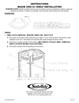
19. Install shelf: drill out dimples (4) located on inside of unit in right rear corner of unit [about 2/3 the way up from
the base on rear / right side panels] using a # 10 Drill bit "be careful not do drill through outside wall of panels".
(See pic. Z) Secure shelf #18857 to panels using rivets Avdel silver #17436 (4). (See pic. AA)
X Y Z AA
20. Install toilet paper dispenser [ if unit has optional #18955 Paperguard 4 roll vertical ] : drill out dimples
(3) located on inside of unit in right front corner of unit [about 1/2 the way up from the base on right door frame /
right side panel] using a # 10 Drill bit "be careful not do drill through outside wall of front / panel". (See pic. BB)
Secure 4 roll toilet paper holder #18955 to front / panel using rivet #17030 (1) on inside at top
of dispenser [toilet paper holder lid needs to be open]. (See pic. CC) Secure 4 roll toilet paper holder #18955
to front / panel using rivet #17030 (2 total, one per side) on outside near bottom of dispenser.
(See pic. DD)
BB CC DD

- 6 -
P/N 18968 REV C 4/9/13
21. Install Decal on Paperguard 4 roll vertical: Decal toilet paper dispenser #19308 (1) centered on front of
toilet paper dispenser over round recess on dispenser. (See pics. EE & FF)
EE FF
/


