Page is loading ...


2
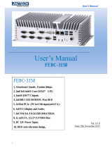
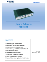
FEBC-5950
1、Aluminum case , Fanless disign;
2、4th Generation Intel® CoreTM processors;
3、Intel® H81 Express Chipset;
4、2xDDR3-1333/1600 SODIMM ,max 16GB;
5、1xmSATA/minipcie,2x2.5inch SATA HDD;
6、DC 9V-36V Wide voltage input;
6、VGA display;
7、6COM/8DIO;
8、2×Intel Gigabit Ethernet (I210&I217);
9、4xPCI or 1xPCI-E x16 + 3xPCI

I
Copyright
The documentation and the software included with this product are copy- righted 2006 by
ShenZhen JHC Technology Co., Ltd. All rights are reserved. ShenZhen JHC Technology
Co., Ltd. reserves the right to make improvements in the products described in this
manual at any time without notice. No part of this manual may be reproduced, copied,
translated or transmitted in any form or by any means without the prior written
permission of ShenZhen JHC Technology Co., Ltd. Information provided in this manual
is intended to be accurate and reliable. However, ShenZhen JHC Technology Co.,
Ltd.assumes no responsibility for its use, nor for any infringements of the rights of third
parties, which may result from its use.
Acknowledgements
Award is a trademark of Award Software International, Inc.
IBM, PC/AT, PS/2 and VGA are trademarks of International Business Machines
Corporation.
Intel and Pentium are trademarks of Intel Corporation.
Microsoft Windows and MS-DOS are registered trademarks of Microsoft Corp.
RTL is a trademark of Realtek Semi-Conductor Co., Ltd.
All other product names or trademarks are properties of their respective owners.
For more information on this and other JHC products, please visit our websites at:
http://www.jhctech.com.cn

II
Product Warranty (2 years)
JHC warrants to you, the original purchaser, that each of its products will be free from
defects in materials and workmanship for two years from the date of purchase.
This warranty does not apply to any products which have been repaired or altered by
persons other than repair personnel authorized by JHC, or which have been subject to
misuse, abuse, accident or improper installation.
JHC assumes no liability under the terms of this warranty as a consequence of such
events.
Because of JHC.s high quality-control standards and rigorous testing,most of our
customers never need to use our repair service. If an JHC product is defective, it will be
repaired or replaced at no charge during the warranty period. For out-of-warranty repairs,
you will be billed according to the cost of replacement materials, service time and freight.
Please consult your dealer for more details.
If you think you have a defective product, follow these steps:
1. Collect all the information about the problem encountered. (For example, CPU
speed, JHC products used, other hardware and software used, etc.) Note anything
abnormal and list any onscreen messages you get when the problem occurs.
2. Call your dealer and describe the problem. Please have your manual, product, and
any helpful information readily available.
3. If your product is diagnosed as defective, obtain an RMA (return merchandise
authorization) number from your dealer. This allows us to process your return more
quickly.
4. Carefully pack the defective product, a fully-completed Repair and Replacement
Order Card and a photocopy proof of purchase date (such as your sales receipt) in a
shippable container. A product returned without proof of the purchase date is not
eligible for warranty service.
5. Write the RMA number visibly on the outside of the package and ship it prepaid to
your dealer.

III
Declaration of Conformity
CE
This product has passed the CE test for environmental specifications
when shielded cables are used for external wiring. We recommend the use
of shielded cables. This kind of cable is available from JHC. Please
contact your local supplier for ordering information. Test conditions for
passing included the equipment being operated within an industrial enclosure.
In order to protect the product from being damaged by ESD (Electrostatic
Discharge) and EMI leakage, we strongly recommend the use of
CE-compliant industrial enclosure products.
FCC Class A
Note: This equipment has been tested and found to comply with the limits for a Class A
digital device, pursuant to part 15 of the FCC Rules. These limits are designed to provide
reasonable protection against harmful interference when the equipment is operated in a
commercial environment This equipment generates, uses, and can radiate radio frequency
energy and, if not installed and used in accordance with the instruction manual, may
cause harmful interference to radio communications. Operation of this equipment in a
residential area is likely to cause harmful interference in which case the user will be
required to correct the interference at his own expense.
Technical Support and Assistance
Step 1. Visit the JHC web site at www.jhctech.com.cn
where you can find the latest information about the product.
Step 2. Contact your distributor, sales representative, or JHC’s customer service center
for technical support if you need additional assistance. Please have the following
information ready before you call:
- Product name and serial number
- Description of your peripheral attachments
- Description of your software (operating system, version,application software,
etc.)
- A complete description of the problem
- The exact wording of any error messages

A
Contents
General Information ............................................................................................................ 1
1.1 Introduction ....................................................................................................... 2
1.2 Features ............................................................................................................. 2
1.3 Specifications .................................................................................................... 2
1.3.1 General .................................................................................................... 2
1.3.2 Display .................................................................................................... 3
1.3.3 Ethernet ...................................................................................................... 3
1.3.4 Power Consumption ................................................................................... 3
1.3.5 Power Requirement .................................................................................... 3
1.4 Environmental Specifications ............................................................................... 3
1.5 Mechanical Specifications .................................................................................... 4
Hardware Installation .......................................................................................................... 5
2.1 Introduction ........................................................................................................... 6
2.2 Jumpers and connectors ........................................................................................ 6
2.2.1 Setting Jumpers .......................................................................................... 6
2.3 Jumper Location.................................................................................................... 6
2.3.1 JP4: Clear CMOS Date .............................................................................. 8
2.3.2 JP1/2 USB Power Select ............................................................................ 9
2.3.3 Auto Power-on Select .............................................................................. 10
2.3.4 COM 1/COM 2 RS232/422/485 Select ....................................................11
2.3.5 COM 1/COM 2 RS232/Power Select ...................................................... 13
2.3.6 Mini PCIe Signal Select ........................................................................... 14
2.3.7 Mini PCIe Power Select ........................................................................... 14
2.3.8 Digital I/O Connectors ............................................................................. 15
2.3.9 Front Panel Connector ............................................................................. 16
2.3.10 SATA Power Connectors ........................................................................ 17
2.4 I/O indication ...................................................................................................... 17
2.4.1 Ethernet Connector (LAN) ...................................................................... 18
2.4.2 Power Input Connector (DC-IN) ............................................................. 19
2.4.3 USB 2.0 Connector .................................................................................. 19
2.4.4 COM1/COM2 Connector......................................................................... 20
2.4.5 COM3/COM4/COM5/COM6 Connector ................................................ 21
2.4.6 DIO Connector ......................................................................................... 21
BIOS Setup ....................................................................................................................... 22
3.1 Main .................................................................................................................... 24
3.2 Advanced............................................................................................................. 25
3.2.1 ACPI Power Management Configuration ................................................ 25
3.2.2 Trusted Computing................................................................................... 26
3.2.3 CPU Configuration .................................................................................. 27
3.2.4 SATA Configuration ................................................................................. 28
3.2.5 PCH-FW Configuration ........................................................................... 30
3.2.6 USB Configuration .................................................................................. 31
3.2.7 Super IO Configuration............................................................................ 32

B
3.2.8 PC Health Status ...................................................................................... 33
3.2.9 Second Super IO Configuration ............................................................... 35
3.2.10 Network Stack ........................................................................................ 37
3.3 Chipset ................................................................................................................ 38
3.3.1 System Agent (SA) Configuration ........................................................... 39
3.3.2 PCH-IO Configuration ............................................................................. 39
3.4 Boot ..................................................................................................................... 40
3.4.1 CSM Parameters ...................................................................................... 41
3.5 Security ............................................................................................................... 42
3.6 Save & Exit ......................................................................................................... 42
Driver Installation ............................................................................................................. 44
4.1 Follow the sequence below to install the drivers: ............................................... 45
4.2 Installation: ......................................................................................................... 45
Watchdog Sample Code .................................................................................................... 46


2
1.1 Introduction
FEBC-5950 is an intelligent,fanless embedded system powered by Intel 4th Generation
Intel® CoreTM processors with multiple I/O interface and 2.5” HDD driver bay.
FEBC-5950 offers 1xVGA interface, 2xGiga Lan ports, 2xUSB3.0 ports, 2xUSB2.0 ports,
6xCOM ports, 1xMini PCIe socket,4xPCI/PCIE socket; The FEBC-5950 supports two
2.5” SATA HDD driver bay,1xmSATA for storage options.
1.2 Features
Key features
1、Aluminum case , Fanless disign;
2、4th Generation Intel® CoreTM processors;
3、2xDDR3-1333/1600 SODIMM ,max 16GB;
4、1xmSATA,2x2.5inch SATA HDD;
5、1xminipcie/mSATA;
6、DC 9V~36V Wide voltage input;
6、VGA display;
7、6COM/8DIO;
8、2×Intel Gigabit Ethernet ;
9、4xPCI or 1xPCI-E x16 + 3xPCI
1.3 Specifications
1.3.1 General
CPU: Intel® CoreTM i3-4330T (4M Cache, 3.0 GHz) 35W;
Intel® Pentium® Processor G3220T (3M Cache, 2.60 GHz) 35W;
Intel® Core™ i5-4670T Processor (6M Cache, up to 3.30 GHz) 45W
BIOS: AMI BIOS
System Memory: Up to 16G DDR3 1333/1600GHz SODIMM
Watchdog Timer: 255-level interval timer, setup by software
Serial Ports:
– 4x RS-232, 2 x RS-232/422/485
DIO:
– 8 bit DIO

3
USB:
– 2 x USB 2.0 compliant Ports, 2xUSB3.0 compliant port.
Expansion Interface: Support up to 1 x full size Mini-PCIe , 4xPCI or 1xPCI-E x16 +
3xPCI
Storage:
– Supports 1 xmSATA
– SATA: Support `2x 2.5” SATAII HDD
1.3.2 Display
Chipset: Intel HD Graphics;
Display Memory: Shared system memery
VGA Resolution: up to 1920x1200 pixels with 24-bit color @ 60Hz
1.3.3 Ethernet
Chipset: 1xIntel WGI210 Gigabit Ethernet; 1x Intel® I217 Gigabit Ethernet Phy
Speed: 10/100/1000 Mbps
Interface: Up to 2 x RJ45
1.3.4 Power Consumption
Input Voltage: DC 9~36V
Power Adapter: AC to DC 19 V/6.32 A, 120 W
1.3.5 Power Requirement
System power:
– Minimum power input: DC 12 V 5 A
1.4 Environmental Specifications
Operating temperature: -10 ~ 55° C (With extended temperature mSATA devices) &
0 ~ 50° C (With standard temperature mSATA&HDD devices)
Relative humidity: 95% @ 40°C (non-condensing)
Storage temperature: -20 ~ 70°C (-40 ~ 185°F)
Vibration loading during operation:
– With SSD/mSATA: 3 Grms, IEC 60068-2-64, random, 5 ~ 500 Hz, 1 hr/axis


6
2.1 Introduction
The following sections show the internal jumper settings and the external connectors and
pin assignments for applications.
2.2 Jumpers and connectors
The FEBC-5950 Embedded Box Computer consists of an JHC SBC (Single Board
Computer) board that is housed in an aluminum plate chassis. Your HDD and SDRAM,
are all readily accessible by removing the aluminum bottom cover. Any maintenance or
hardware upgrades can be easily completed after removing the bottom cover.
Warning:Do not remove any mechanical parts until you have verified that no power is
flowing within the Embedded Box Computer. Power must be switched off and the power
cord must be unplugged.
2.2.1 Setting Jumpers
You can configure your FEBC-5950 to match the needs of your application by setting the
jumpers. A jumper is the simplest kind of electrical switch. It consists of two metal pins
and a small metal clip (often protected by a plastic cover) that slides over the pins to
connect them. To —close“ a jumper, you connect the pins with the clip. To —open“ a
jumper you remove the clip. Sometimes a jumper will have three pins, labeled 1, 2, and 3.
In this case, you would connect either pins 1 and 2 or pins 2 and 3.
The jumper settings are schematically depicted in this manual as follows:
A pair of needle-nose pliers may be helpful when working with jumpers. If you have any
doubts about the best hardware configuration for your application, contact your local
distributor or sales representative before you make any changes.
2.3 Jumper Location
The FEBC-5950 Embedded Box Computer has a number of jumpers inside the chassis
that allows you to configure your system to suit your application. The table below lists
the functions of the various jumpers. The table below shows the function of each of the
board's jumpers:

7
Jumpers
Jumper
Name
Description
JP4
Clear CMOS Date
3-Pin Block
JP1
USB power select
3-Pin Block
JP2
USB power select
3-Pin Block
JP7
Auto Power-on Select
3-Pin Block
JP8
COM1 RS232/422/485 select
6-Pin Block
JP11
6-Pin Block
JP13
6-Pin Block
JP14
COM1 RS232/power select
6-pin Block
JP12
COM2 RS232/422/485 select
6-pin Block
JP15
6-pin Block
JP17
6-pin Block
JP18
COM4 RS232/power select
6-pin Block
JP9
Mini PCIe Signal Select
12-pin Block
JP6
Mini PCIe Power Select
3-Pin Block

8
Headers
Header
Name
Description
Front Panel
Front Panel header
11-pin block
SATA Power 0/SATA
Power 1
SATA (Serial ATA) Power Connectors
5-pin block
KB/MS
PS/2 Keyboard/Mouse Connector
9-pin block
COM2/COM3/
COM4/COM5/
COM6
Serial port headers
9-pin block
Digital I/O
Digital I/O Connector
8-Pin block
2.3.1 JP4: Clear CMOS Date
If you encounter the following,
a) CMOS data becomes corrupted.
b) You forgot the supervisor or user password.
you can reconfigure the system with the default values stored in the ROM BIOS. To load
the default values stored in the ROM BIOS, please follow the steps below.
1. Power-off the system and unplug the power cord.
2. Set JP4 pins 2 and 3 to On. Wait for a few seconds and set JP4 back to its default
setting, pins 1 and 2 On.

9
3. Now plug the power cord and power-on the system.
2.3.2 JP1/2 USB Power Select
JP1, JP2 are used to select the power of the USB ports. Selecting +5V_standby will allow
you to use a USB device to wake up the system.
Important:
If you are using the Wake-On-USB Keyboard/Mouse function for 2 USB ports,
the+5V_standby power source of your power supply must support ≥1.5A. For 3 or
moreUSB ports, the +5V_standby power source of your power supply must
support ≥2A.

10
2.3.3 Auto Power-on Select
JP7 is used to select the method of powering on the system. If you want the system to
power-on whenever AC power comes in, set JP7 pins 2 and 3 to On. If you want to use
the powerbutton, set pins 1 and 2 to On.
When using the JP7 “Power On” feature to power the system back on after a power
failure occurs, the system may not power on if the power lost is resumed within 5
seconds (power flicker).

11
2.3.4 COM 1/COM 2 RS232/422/485 Select
These jumpers allow you to configure the Serial COM ports to RS232, RS422 (Full
Duplex) or RS485. JP8, JP11 and JP13 are used to configure the Serial COM port 1. JP12,
JP15 and JP17 are used to configure the Serial COM port 2. The pin functions of Serial
COM ports 1 and 2 will vary according to these jumpers’ setting.
Note:
When COM 1 RS232/422/485 is selected, JP11 and JP13 must be set in accordance to JP8. And
when COM 2 RS232/422/485 is selected, JP15 and JP17 must be set in accordante to JP12.


/