Page is loading ...

INVERTER
INVERTER FR-E860
Instruction Manual (Connection) (575V CLASS)
E
HEAD OFFICE: TOKYO BUILDING 2-7-3, MARUNOUCHI, CHIYODA-KU, TOKYO 100-8310, JAPAN
IB(NA)-0600906ENG-D(2104)MEE Printed in Japan Specifications subject to change without notice.
FR-E860
Instruction Manual (Connection)
(575V CLASS)
FR-E860-0017(0.75K) to 0120(7.5K)
FR-E860-0017(0.75K) to 0120(7.5K)E
FR-E860-0017(0.75K) to 0120(7.5K)SCE
Compact, high functionality inverters

1
CONTENTS
Safety Instructions . . . . . . . . . . . . . . . . . . . . . . . . . . . . . . . . . . . . . . . . . . . . . . . . . . . . . . . . . . . . . . . . 3
Chapter 1 Introduction . . . . . . . . . . . . . . . . . . . . . . . . . . . . . . . . . 10
1.1 Product checking and accessories . . . . . . . . . . . . . . . . . . . . . . . . . . . . . . . . . . . . . . . . . . . . . 11
1.2 Component names . . . . . . . . . . . . . . . . . . . . . . . . . . . . . . . . . . . . . . . . . . . . . . . . . . . . . . . . . 13
1.3 Operation steps . . . . . . . . . . . . . . . . . . . . . . . . . . . . . . . . . . . . . . . . . . . . . . . . . . . . . . . . . . . . 16
1.4 Related manuals . . . . . . . . . . . . . . . . . . . . . . . . . . . . . . . . . . . . . . . . . . . . . . . . . . . . . . . . . . . 18
Chapter 2 Installation and Wiring . . . . . . . . . . . . . . . . . . . . . . . . 20
2.1 Peripheral devices . . . . . . . . . . . . . . . . . . . . . . . . . . . . . . . . . . . . . . . . . . . . . . . . . . . . . . . . . . 20
2.1.1 Inverter and peripheral devices. . . . . . . . . . . . . . . . . . . . . . . . . . . . . . . . . . . . . . . . . . . . . . . . . . . . . . . . . . . . . . . . . . . . . . 20
2.1.2 Peripheral devices. . . . . . . . . . . . . . . . . . . . . . . . . . . . . . . . . . . . . . . . . . . . . . . . . . . . . . . . . . . . . . . . . . . . . . . . . . . . . . . . 22
2.2 Removal and reinstallation of the front cover . . . . . . . . . . . . . . . . . . . . . . . . . . . . . . . . . . . . . 24
2.3 Installation of the inverter and enclosure design . . . . . . . . . . . . . . . . . . . . . . . . . . . . . . . . . . . 26
2.3.1 Inverter installation environment . . . . . . . . . . . . . . . . . . . . . . . . . . . . . . . . . . . . . . . . . . . . . . . . . . . . . . . . . . . . . . . . . . . . . 26
2.3.2 Amount of heat generated by the inverter. . . . . . . . . . . . . . . . . . . . . . . . . . . . . . . . . . . . . . . . . . . . . . . . . . . . . . . . . . . . . . 28
2.3.3 Output current reduction when the surrounding air temperature is between 50°C and 60°C . . . . . . . . . . . . . . . . . . . . . . . 29
2.3.4 Standby power consumption by the inverter . . . . . . . . . . . . . . . . . . . . . . . . . . . . . . . . . . . . . . . . . . . . . . . . . . . . . . . . . . . . 29
2.3.5 Cooling system types for inverter enclosure . . . . . . . . . . . . . . . . . . . . . . . . . . . . . . . . . . . . . . . . . . . . . . . . . . . . . . . . . . . . 29
2.3.6 Inverter installation . . . . . . . . . . . . . . . . . . . . . . . . . . . . . . . . . . . . . . . . . . . . . . . . . . . . . . . . . . . . . . . . . . . . . . . . . . . . . . . 30
2.4 Terminal connection diagrams. . . . . . . . . . . . . . . . . . . . . . . . . . . . . . . . . . . . . . . . . . . . . . . . . 33
2.5 Main circuit terminals . . . . . . . . . . . . . . . . . . . . . . . . . . . . . . . . . . . . . . . . . . . . . . . . . . . . . . . . 42
2.5.1 Details on the main circuit terminals . . . . . . . . . . . . . . . . . . . . . . . . . . . . . . . . . . . . . . . . . . . . . . . . . . . . . . . . . . . . . . . . . . 42
2.5.2 Main circuit terminal layout and wiring to power supply and motor. . . . . . . . . . . . . . . . . . . . . . . . . . . . . . . . . . . . . . . . . . . 42
2.5.3 Applicable cables and wiring length . . . . . . . . . . . . . . . . . . . . . . . . . . . . . . . . . . . . . . . . . . . . . . . . . . . . . . . . . . . . . . . . . . 43
2.5.4 Earthing (grounding) precautions . . . . . . . . . . . . . . . . . . . . . . . . . . . . . . . . . . . . . . . . . . . . . . . . . . . . . . . . . . . . . . . . . . . . 46
2.6 Control circuit. . . . . . . . . . . . . . . . . . . . . . . . . . . . . . . . . . . . . . . . . . . . . . . . . . . . . . . . . . . . . . 47
2.6.1 Details on the control circuit terminals (Standard model) . . . . . . . . . . . . . . . . . . . . . . . . . . . . . . . . . . . . . . . . . . . . . . . . . . 47
2.6.2 Details on the control circuit terminals (Ethernet model). . . . . . . . . . . . . . . . . . . . . . . . . . . . . . . . . . . . . . . . . . . . . . . . . . . 50
2.6.3 Details on the control circuit terminals (Safety communication model). . . . . . . . . . . . . . . . . . . . . . . . . . . . . . . . . . . . . . . . 52
2.6.4 Control logic (sink/source) change (Standard model / Ethernet model) . . . . . . . . . . . . . . . . . . . . . . . . . . . . . . . . . . . . . . . 54
2.6.5 Wiring of control circuit . . . . . . . . . . . . . . . . . . . . . . . . . . . . . . . . . . . . . . . . . . . . . . . . . . . . . . . . . . . . . . . . . . . . . . . . . . . . 56
2.6.6 Wiring precautions . . . . . . . . . . . . . . . . . . . . . . . . . . . . . . . . . . . . . . . . . . . . . . . . . . . . . . . . . . . . . . . . . . . . . . . . . . . . . . . 60
2.6.7 Safety stop function (Standard model / Ethernet model) . . . . . . . . . . . . . . . . . . . . . . . . . . . . . . . . . . . . . . . . . . . . . . . . . . 61
2.6.8 Safety communication function (Safety communication model) . . . . . . . . . . . . . . . . . . . . . . . . . . . . . . . . . . . . . . . . . . . . . 63
2.7 Connection to a motor with encoder (Vector control) . . . . . . . . . . . . . . . . . . . . . . . . . . . . . . . 65
2.8 Communication connectors and terminals. . . . . . . . . . . . . . . . . . . . . . . . . . . . . . . . . . . . . . . . 70
2.8.1 PU connector (Standard model) . . . . . . . . . . . . . . . . . . . . . . . . . . . . . . . . . . . . . . . . . . . . . . . . . . . . . . . . . . . . . . . . . . . . . 70
2.8.2 Ethernet connector (Ethernet model / Safety communication model). . . . . . . . . . . . . . . . . . . . . . . . . . . . . . . . . . . . . . . . . 71

2
2.8.3 USB connector . . . . . . . . . . . . . . . . . . . . . . . . . . . . . . . . . . . . . . . . . . . . . . . . . . . . . . . . . . . . . . . . . . . . . . . . . . . . . . . . . . 73
2.9 Connection of stand-alone option units . . . . . . . . . . . . . . . . . . . . . . . . . . . . . . . . . . . . . . . . . . 74
2.9.1 Connection of the brake resistor . . . . . . . . . . . . . . . . . . . . . . . . . . . . . . . . . . . . . . . . . . . . . . . . . . . . . . . . . . . . . . . . . . . . . 74
2.9.2 Connection of the DC reactor . . . . . . . . . . . . . . . . . . . . . . . . . . . . . . . . . . . . . . . . . . . . . . . . . . . . . . . . . . . . . . . . . . . . . . . 75
Chapter 3 Precautions for Use of the Inverter. . . . . . . . . . . . . . 78
3.1 Electro-magnetic interference (EMI) and leakage currents . . . . . . . . . . . . . . . . . . . . . . . . . . .78
3.1.1 Leakage currents and countermeasures. . . . . . . . . . . . . . . . . . . . . . . . . . . . . . . . . . . . . . . . . . . . . . . . . . . . . . . . . . . . . . . 78
3.1.2 Techniques and measures for electromagnetic compatibility (EMC) . . . . . . . . . . . . . . . . . . . . . . . . . . . . . . . . . . . . . . . . . 79
3.2 Power supply harmonics . . . . . . . . . . . . . . . . . . . . . . . . . . . . . . . . . . . . . . . . . . . . . . . . . . . . . 82
3.2.1 Power supply harmonics . . . . . . . . . . . . . . . . . . . . . . . . . . . . . . . . . . . . . . . . . . . . . . . . . . . . . . . . . . . . . . . . . . . . . . . . . . . 82
3.3 Installation of a reactor . . . . . . . . . . . . . . . . . . . . . . . . . . . . . . . . . . . . . . . . . . . . . . . . . . . . . . .83
3.4 Power shutdown and magnetic contactor (MC) . . . . . . . . . . . . . . . . . . . . . . . . . . . . . . . . . . . .84
3.5 Countermeasures against deterioration of the 600 V class motor insulation . . . . . . . . . . . . . .86
3.6 Checklist before starting operation. . . . . . . . . . . . . . . . . . . . . . . . . . . . . . . . . . . . . . . . . . . . . .87
3.7 Failsafe system which uses the inverter. . . . . . . . . . . . . . . . . . . . . . . . . . . . . . . . . . . . . . . . . .90
Chapter 4 Specifications . . . . . . . . . . . . . . . . . . . . . . . . . . . . . . . 94
4.1 Inverter rating . . . . . . . . . . . . . . . . . . . . . . . . . . . . . . . . . . . . . . . . . . . . . . . . . . . . . . . . . . . . . .94
4.2 Common specifications . . . . . . . . . . . . . . . . . . . . . . . . . . . . . . . . . . . . . . . . . . . . . . . . . . . . . .95
4.3 Outline dimension drawings . . . . . . . . . . . . . . . . . . . . . . . . . . . . . . . . . . . . . . . . . . . . . . . . . . .97
4.3.1 Inverter outline dimension drawings (Standard model). . . . . . . . . . . . . . . . . . . . . . . . . . . . . . . . . . . . . . . . . . . . . . . . . . . . 97
4.3.2 Inverter outline dimension drawings (Ethernet model / Safety communication model). . . . . . . . . . . . . . . . . . . . . . . . . . . . 99
Chapter 5 Appendix . . . . . . . . . . . . . . . . . . . . . . . . . . . . . . . . . . 102
5.1 How to check specification changes . . . . . . . . . . . . . . . . . . . . . . . . . . . . . . . . . . . . . . . . . . .102
5.1.1 Details of specification changes . . . . . . . . . . . . . . . . . . . . . . . . . . . . . . . . . . . . . . . . . . . . . . . . . . . . . . . . . . . . . . . . . . . . 102

3
Safety Instructions
Thank you for choosing Mitsubishi Electric inverter.
This Instruction Manual provides detailed instructions for advanced settings of the FR-E800 series inverters.
Incorrect handling might cause an unexpected fault. Before using this product, read this Instruction Manual and the document
enclosed with the product carefully to ensure proper use.
Do not attempt to install, operate, maintain or inspect this product until you have read the Instruction Manuals and appended
documents carefully. Do not use this product until you have a full knowledge of this product mechanism, safety information and
instructions.
Installation, operation, maintenance and inspection must be performed by qualified personnel. Here, qualified personnel means
a person who meets all the following conditions:
• A person who possesses a certification in regard with electric appliance handling, or person took a proper engineering
training. Such training may be available at your local Mitsubishi Electric office. Contact your local sales office for schedules
and locations.
• A person who can access operating manuals for the protective devices (for example, light curtain) connected to the safety
control system, or a person who has read these manuals thoroughly and familiarized themselves with the protective
devices.
In this Instruction Manual, the safety instruction levels are classified into "WARNING" and "CAUTION".
Note that even the level may lead to a serious consequence depending on conditions. Be sure to follow the
instructions of both levels as they are critical to personnel safety.
WARNING
CAUTION
Incorrect handling may cause hazardous conditions, resulting in death or severe injury.
Incorrect handling may cause hazardous conditions, resulting in medium or slight injury,
or may cause only material damage.

Electric shock prevention
Fire prevention
Injury prevention
WARNING
Do not remove the front cover or the wiring cover while the power of this product is ON, and do not run this product with
the front cover or the wiring cover removed as the exposed high voltage terminals or the charging part of the circuitry
can be touched. Otherwise you may get an electric shock.
Even if power is OFF, do not remove the front cover except for wiring or periodic inspection as the inside of this product
is charged. Otherwise you may get an electric shock.
Before wiring or inspection, check that the LED display of the operation panel is OFF. Any person who is involved in
wiring or inspection shall wait for 10 minutes or longer after the power supply has been cut off, and check that there are
no residual voltage using a digital multimeter or the like. The capacitor is charged with high voltage for some time after
power OFF, and it is dangerous.
Be sure to earth (ground) the inverter. Earthing (grounding) must conform to the requirements of national and local safety
regulations and electrical code (NEC section 250, IEC 61140 class 1 and other applicable standards).
Any person who is involved in wiring or inspection of this product shall be fully competent to do the work.
This product body must be installed before wiring. Otherwise you may get an electric shock or be injured.
Do not touch the setting dial or keys with wet hands. Doing so may cause an electric shock.
Do not subject the cables to scratches, excessive stress, heavy loads or pinching. Doing so may cause an electric shock.
Do not change the cooling fan while power is ON as it is dangerous.
Do not touch the printed circuit board or handle the cables with wet hands. Doing so may cause an electric shock.
Never touch the motor terminals, etc. right after powering OFF as the DC voltage is applied to the motor for 1 second at
powering OFF if the main circuit capacitor capacity is measured. Doing so may cause an electric shock.
Before wiring or inspection for a PM motor, confirm that the PM motor is stopped as a PM motor is a synchronous motor
with high-performance magnets embedded inside and high-voltage is generated at the motor terminals while the motor
is running even after the power of this product is turned OFF. In an application, such as fan and blower, that the motor
may be driven by the load, connect a low-voltage manual contactor at the output side of this product and keep it open
during wiring and inspection of this product. Otherwise you may get an electric shock.
CAUTION
This product must be installed on a nonflammable wall without holes in it so that its components cannot be touched from
behind. Installing it on or near flammable material may cause a fire.
If this product becomes faulty, the product power must be switched OFF. A continuous flow of large current may cause
a fire.
When using a brake resistor, a sequence that will turn OFF power when a fault signal is output must be configured.
Otherwise the brake resistor may excessively overheat due to damage of the brake transistor and such, causing a fire.
Do not connect a resistor directly to the DC terminals P/+ and N/-. Doing so could cause a fire.
Across terminals P/+ and PR, connect only an external brake resistor.
Be sure to perform daily and periodic inspections as specified in the Instruction Manual (Maintenance). There is a
possibility of explosion, damage, or fire if this product is used without inspection.
CAUTION
The voltage applied to each terminal must be as specified in the Instruction Manual. Otherwise an explosion or damage
may occur.
The cables must be connected to the correct terminals. Otherwise an explosion or damage may occur.
The polarity (+ and -) must be correct. Otherwise an explosion or damage may occur.
While power is ON or for some time after power-OFF, do not touch this product as it will be extremely hot. Doing so may
cause burns.

5
Additional instructions
The following instructions must be also followed. If the product is handled incorrectly, it may cause unexpected fault, an injury,
or an electric shock.
CAUTION
Transportation and installation
To prevent injury, wear cut-resistant gloves when opening packaging with sharp tools.
Use proper lifting techniques or a trolley when carrying products. Failure to do so may lead to injuries.
Do not stand or place any heavy object on this product.
Do not stack the boxes containing this product higher than the number recommended.
When carrying this product, do not hold it by the front cover or the setting dial. It may fall or break.
During installation, caution must be taken not to drop this product as doing so may cause injuries.
The product must be installed on a surface that withstands the weight of the product.
Do not install the product on a hot surface.
Ensure the mounting orientation of this product is correct.
Ensure this product is mounted securely with screws in its enclosure.
Do not install or operate this product if it is damaged or has parts missing.
Foreign conductive objects must be prevented from entering this product. That includes screws and metal fragments or
other flammable substance such as oil.
As this product is a precision instrument, do not drop or subject it to impact.
The surrounding air temperature must be between -10°C and +60°C (non-freezing). The rated current must be reduced
at a surrounding air temperature above 50°C. The rated current must be reduced at a surrounding air temperature above
50°C. Otherwise this product may be damaged.
The ambient humidity must be 90% RH or less (non-condensing) for models without circuit board coating and 95% RH
or less (non-condensing) for models with circuit board coating. Otherwise this product may be damaged.
The temporary storage temperature (applicable to a short limited time such as a transportation time) must be between -
40°C and +70°C. Otherwise this product may be damaged.
This product must be used indoors (without corrosive gas, flammable gas, oil mist, dust and dirt). Otherwise this product
may be damaged.
Do not use this product at an altitude above 2000 m. Vibration should not exceed 5.9 m/s
2
at 10 to 55 Hz in X, Y, and Z
directions. Otherwise this product may be damaged. (Refer to page 26 for details.)
If halogens (including fluorine, chlorine, bromine, and iodine) contained in fumigants for wood packages enter this
product, the product may be damaged. Prevent the entry of fumigant residuals or use an alternative method such as heat
disinfection. Note that sterilization or disinfection of wood packages should be performed before packing the product.
Wiring
Do not install a power factor correction capacitor, surge absorber, or radio noise filter on the output side of this product.
These devices may overheat or burn out.
The output terminals (terminals U, V, and W) must be connected to a motor correctly. Otherwise the motor will rotate
inversely.
Even with the power OFF, high voltage is still applied to the terminals U, V and W while the PM motor is running. Ensure
the PM motor has stopped before carrying out any wiring. Otherwise you may get an electric shock.
Never connect a PM motor to a commercial power supply. Connecting a commercial power supply to the input terminals
(U, V, W) of a PM motor will burn it out. The PM motor must be applied a power from the inverter with the output terminals
(U, V, W).
Test operation
Before starting the operation, confirm or adjust the parameter settings. Failure to do so may cause some machines to
make unexpected motions.

WARNING
Usage
Stay away from the equipment after using the retry function in this product as the equipment will restart suddenly after
the output shutoff of this product.
Access to the motor is allowed only after it is fully confirmed that the motor does not start running.
Depending on the function settings of this product, the product does not stop its output even when the STOP/RESET
key on the operation panel is pressed. To prepare for it, provide a separate circuit and switch (to turn OFF the power of
this product, or apply a mechanical brake, etc.) for an emergency stop.
Be sure to turn OFF the start (STF/STR) signal before clearing the fault as this product will restart the motor suddenly
after a fault is cleared.
Do not use a PM motor for an application that the motor may be driven by the load and run at a speed higher than the
maximum motor speed.
Use only a three-phase induction motor or PM motor as a load on this product. Connection of any other electrical
equipment to the output of this product may damage the equipment.
Performing pre-excitation (LX signal and X13 signal) under torque control may start the motor running at a low speed
even when the start signal (STF or STR) is not input. This product with the start command ON may also rotate the motor
at a low speed when the speed limit value is set to zero. Confirm that the motor running does not cause any safety
problems before performing pre-excitation.
Do not modify this product.
Do not remove any part which is not instructed to be removed in the Instruction Manuals. Doing so may lead to a failure
or damage of this product.

7
*1 DoS: A denial-of-service (DoS) attack disrupts services by overloading systems or exploiting vulnerabilities, resulting in a denial-of-service (DoS)
state.
CAUTION
Usage
When installing the MC on the output side of the inverter, turn it ON/OFF while both the inverter and motor are at a stop.
The electronic thermal O/L relay function may not be enough for protection of a motor from overheating. It is
recommended to install an external thermal relay or a PTC thermistor for overheat protection.
Do not repeatedly start or stop this product with a magnetic contactor on its input side. Doing so may shorten the life of
this product.
Use a noise filter or other means to minimize electromagnetic interference with other electronic equipment used nearby
this product.
Appropriate precautions must be taken to suppress harmonics. Otherwise harmonics in power systems generated from
this product may heat/damage a power factor correction capacitor or a generator.
To drive a 600 V class motor with this product, use an insulation-enhanced motor, or take measures to suppress surge
voltage. Otherwise surge voltage, which is attributed to the length and thickness of wire, may occur at the motor
terminals, causing the motor insulation to deteriorate.
When a motor is driven by the inverter, axial voltage is generated on the motor shaft, which may cause electrical
corrosion of the bearing. Take measures such as decreasing the carrier frequency.
As all parameters return to their initial values after the Parameter clear or All parameter clear is performed, the needed
parameters for this product operation must be set again before the operation is started.
This product can be easily set for high-speed operation. Therefore, consider all things related to the operation such as
the performance of a motor and equipment in a system before the setting change.
This product's brake function cannot be used as a mechanical brake. Use a separate device instead.
When performing an inverter operation with frequent starts/stops, rise/fall in the temperature of the transistor element of
the inverter will repeat due to a repeated flow of large current, shortening the life.
Perform an inspection and test operation of this product if it has been stored for a long period of time.
To avoid damage to this product due to static electricity, static electricity in your body must be discharged before you
touch this product.
Only one PM motor can be connected to a single unit of this product.
A PM motor must be used under PM sensorless vector control. Do not use a synchronous motor, induction motor, or
synchronous induction motor.
Do not connect a PM motor to this product with it set to the induction motor control setting (initial setting). Do not connect
an induction motor to this product with it set to the PM sensorless vector control setting. Doing so will cause failure.
As a process of starting a PM motor, turn ON the power of this product first, and then close the contactor on the output
side of this product.
To maintain the security (confidentiality, integrity, and availability) of the inverter and the system against unauthorized
access, DoS
*1
attacks, computer viruses, and other cyberattacks from external devices via network, take appropriate
measures such as firewalls, virtual private networks (VPNs), and antivirus solutions. We shall have no responsibility or
liability for any problems involving inverter trouble and system trouble by DoS attacks, unauthorized access, computer
viruses, and other cyberattacks.
Depending on the network environment, the inverter may not operate as intended due to delays or disconnection in
communication. Carefully consider what type of environment the inverter will be used in and any safety issues related to
its use.
When the emergency drive function is enabled, the operation is continued or the retry operation (automatic reset and
restart) is repeated even if a fault occurs, which may damage or burn this product and the motor. Before restarting the
normal operation after the operation using the emergency drive function, make sure that this product and the motor have
no fault.

Compliance with the EU Machinery Directive—Safety functions
To achieve functional safety, any work on the product such as wiring and inspections must be performed according to this
document and the FR-E800-SCE Instruction Manual (Functional Safety) by technicians who took a safety standard training.
CAUTION
Emergency stop
A safety backup such as an emergency brake must be provided for devices or equipment in a system to prevent
hazardous conditions in case of failure of this product or an external device controlling this product.
If the breaker installed on the input side of this product trips, check for wiring faults (such as short circuits) and damage
to internal parts of this product. Identify and remove the cause of the trip before resetting the tripped breaker (or before
applying the power to this product again).
When any protective function is activated, take an appropriate corrective action before resetting this product to resume
the operation.
Maintenance, inspection and parts replacement
Do not carry out a megger (insulation resistance) test on the control circuit of this product. Doing so will cause failure.
Disposal
This product must be treated as industrial waste.
WARNING
Any misuse of safety functions may cause physical injury, damage to property, or economic loss. To confirm that the
system is compliant with safety standards, a risk assessment must be conducted for the entire system. We shall not be
liable for the compliance of the system with safety standards.
To avoid an electric shock hazard, verify that the voltage on the bus capacitors has discharged before working on the
inverter. Measure the DC bus voltage between terminals P/+ and N/- or other measurement points to verify zero voltage.
(For the measurement points and the capacitor discharge time, refer to the FR-E800 Instruction Manual (Maintenance).)
When the power supply to the gate drive circuit is shut off by a safety function, the inverter and the motor are not insulated
each other. To avoid an electric shock hazard, verify that the voltage on the bus capacitors has discharged before wiring
or inspection of the motor. Measure the DC bus voltage between terminals P/+ and N/- or other measurement points to
verify zero voltage. (For the measurement points and the capacitor discharge time, refer to the FR-E800 Instruction
Manual (Maintenance).)
CAUTION
We shall not be liable for the compliance or non-compliance with any local, national, or international codes or regulations
for the installation of this product.
Installation not compliant with applicable codes or directives may cause physical injury or damage to property.
General instruction
For clarity, illustrations in this Instruction Manual may be drawn with covers or safety guards removed. Ensure all covers
and safety guards are properly installed prior to starting operation. For details on the PM motor, refer to the Instruction
Manual of the PM motor.

9
CHAPTER 1
CHAPTER 1
Introduction
1.1 Product checking and accessories .........................................................................................................................11
1.2 Component names .................................................................................................................................................13
1.3 Operation steps ......................................................................................................................................................16
1.4 Related manuals.....................................................................................................................................................18

10
1. Introduction
1 Introduction
The contents described in this chapter must be read before using this product.
Always read the instructions before use.
Abbreviations
Trademarks
• EtherCAT® is a registered trademark and patented technology, licensed by Beckhoff Automation GmbH, Germany.
• Ethernet is a registered trademark of Fuji Xerox Corporation in Japan.
• MODBUS is a registered trademark of SCHNEIDER ELECTRIC USA, INC.
• BACnet is a registered trademark of the American Society of Heating, Refrigerating and Air-Conditioning Engineers
(ASHRAE).
• DeviceNet and EtherNet/IP are registered trademarks of ODVA (Open DeviceNet Vendor Association, INC).
• PROFIBUS and PROFINET are either trademarks or registered trademarks of PROFIBUS & PROFINET International.
• CC-Link IE TSN and CC-Link IE Field Network Basic are registered trademarks of CC-Link Partner Association.
• Other company and product names herein are the trademarks and registered trademarks of their respective owners.
Notes on descriptions in this Instruction Manual
• Connection diagrams in this Instruction Manual appear with the control logic of the input terminals as sink logic, unless
otherwise specified. (For the control logic, refer to page 54.)
Item Description
PU
Operation panel, parameter unit (FR-PU07), LCD operation panel (FR-LU08), and enclosure surface
operation panel (FR-PA07)
Parameter unit
Parameter unit (FR-PU07), LCD operation panel (FR-LU08), and enclosure surface operation panel (FR-
PA07)
Inverter Mitsubishi Electric FR-E800 series inverter
E800 Standard model (RS485 + SIL2/PLd functional safety)
E800-E Ethernet model (Ethernet + SIL2/PLd functional safety)
E800-SCE Safety communication model (Ethernet + SIL3/PLe functional safety)
FM type inverter Standard model with terminal FM (pulse output)
AM type inverter Standard model with terminal AM (voltage output)
Vector control compatible option FR-A8AP E kit
Pr. Parameter number (Number assigned to function)
PU operation Operation using the PU (operation panel / parameter unit)
External operation Operation using the control circuit signals
Combined operation Combined operation using the PU (operation panel / parameter unit) and External operation

11
1. Introduction
1.1 Product checking and accessories
1
2
3
4
5
6
7
8
9
10
1.1 Product checking and accessories
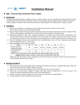
Unpack the product and check the rating plate and the capacity plate of the inverter to ensure that the model agrees with the
order and the product is intact.
Inverter model
• A: The voltage class is shown.
• B: The inverter rated capacity or the inverter rated current is shown.
• C: The communication type and the functional safety specification are shown.
)5(
A B C D E
Rating plate
Input rating
Output rating
SERIAL
Inverter model
INPUT :XXXXX
MODEL :FR-E860-0017-1
OUTPUT:XXXXX
SERIAL:XXXXXXXXXXX
MADE IN XXXXX
Country of origin
-1
6
0017
Symbol Voltage class
6 575 V class
Symbol Description
0.75K to 7.5K Inverter ND rated capacity (kW)
0017 to 0120 Inverter ND rated current (A)
Symbol Communication / functional safety
None Standard model (RS-485 + SIL2/PLd)
E Ethernet model (Ethernet + SIL2/PLd)
SCE
Safety communication model (Ethernet +
SIL3/PLe functional safety)

12
1. Introduction
1.1 Product checking and accessories
• E: The output specification for monitoring and the rated frequency are shown for the standard model, and the
communication protocol group is shown for the Ethernet model and the safety communication model. The control logic is
fixed to the source logic for the safety communication model.
*1 The initial status of the control logic differs depending on the inverter model.
Sink logic for the models indicated with the rated capacity (kW)
Source logic for the models indicated with the rated current (A).
*2 Available for the Ethernet model only.
• E: Availability of circuit board coating / plated conductors is shown.
*1 Conforming to IEC 60721-3-3:1994 3C2
NOTE
• In this Instruction Manual, the inverter model name consists of the inverter rated current and the applicable motor capacity.
(Example) FR-E860-0017(0.75K)
Accessory
• Fan cover fixing screws
These screws are necessary for compliance with the EU Directives. For details, refer to the document enclosed with the
product.
• Brake resistor
How to read the SERIAL number
Sym
bol
Monitoring/protocol specifications
Rated
frequency
(initial
setting)
Control logic
Input signal
(initial status)
Safety stop signal
-1 Pulse (terminal FM) 60 Hz Sink logic
Source logic
(fixed)
-4 Voltage (terminal AM) 50 Hz Source logic
-5 Voltage (terminal AM) 60 Hz Sink logic
PA
Protocol group A (CC-Link IE TSN, CC-Link IE Field Network Basic,
MODBUS/TCP, EtherNet/IP, and BACnet/IP)
60 Hz Sink logic
PB
Protocol group B (CC-Link IE TSN, CC-Link IE Field Network Basic,
MODBUS/TCP, PROFINET)
50 Hz
Sink logic / source
logic
*1
PC
*2
Protocol group C (EtherCAT) 50 Hz
Sink logic / source
logic
*1
Symbol Circuit board coating
*1
Plated conductor
None Without coating Without plated conductors
-60 With coating Without plated conductors
Capacity Screw size (mm) Quantity
FR-E860-0017(0.75K) to 0120(7.5K) M3 × 35 1
The SERIAL consists of two symbols, three characters indicating the production year
and month, and six characters indicating the control number.
The last two digits of the production year are indicated as the Year, and the Month is
indicated by 1 to 9, X (October), Y (November), or Z (December).
Rating plate example
Symbol Year Month Control number
SERIAL

13
1. Introduction
1.2 Component names
1
2
3
4
5
6
7
8
9
10
1.2 Component names
Standard model
Component names are as follows.
*1 Refer to the FR-E800 Instruction Manual (Function).
*2 Refer to the FR-E800 Instruction Manual (Maintenance).
(j)
(a)
(b)
(g)
(h)
(i)
(e)
(k)
(d)
(c)
(f)
(l)
Symbol Name Description
Refer to
page
(a) Plug-in option connection connector Connects a plug-in option or a communication option.
Instruction
Manual of
each option
(b) Control logic switch Select the sink logic (SINK) or the source logic (SOURCE). 54
(c)
Voltage/current input switch
Select voltage or current for the input via terminals 2 and 4.
*1
(d) PU connector Used for the RS-485 communication. 70
(e) Operation panel
Operates and monitors the inverter. The operation panel cannot be
removed from the inverter.
*1
(f)
USB mini B connector Connector for a personal computer. Enables communication with FR
Configurator2.
73
(g) Control circuit terminal block Connects cables for the control circuit. 47
(h) Main circuit terminal block Connects cables for the main circuit. 42
(i) Comb-shaped wiring cover This cover is removable without unplugging cables. 24
(j) Front cover Remove this cover for wiring. 24
(k) Cooling fan Cools the inverter
*2
(l) Earth plate Connects the option and the inverter for earthing (grounding).
Instruction
Manual of
each option

14
1. Introduction
1.2 Component names
Ethernet model
Component names are as follows.
*1 Refer to the FR-E800 Instruction Manual (Function).
*2 Refer to the FR-E800 Instruction Manual (Maintenance).
(j)
(a)
(b)
(c)
(g)
(h)
(i)
(e)
(k)
(f)
(d)
(l)
Symbol Name Description
Refer to
page
(a) Plug-in option connection connector Connects a plug-in option or a communication option.
Instruction
Manual of
each option
(b) Control logic switch Select the sink logic (SINK) or the source logic (SOURCE). 54
(c)
Voltage/current input switch
Select voltage or current for the input via terminals 2 and 4.
*1
(d) Ethernet connector (2 ports) Connector for the Ethernet dedicated cable for connection to the network. 71
(e) Operation panel
Operates and monitors the inverter. The operation panel cannot be removed
from the inverter.
*1
(f)
USB mini B connector Connector for a personal computer. Enables communication with FR
Configurator2.
73
(g) Control circuit terminal block Connects cables for the control circuit. 47
(h) Main circuit terminal block Connects cables for the main circuit. 42
(i) Comb-shaped wiring cover This cover is removable without unplugging cables. 24
(j) Front cover Remove this cover for wiring. 24
(k)
Cooling fan Cools the inverter
*2
(l) Earth plate Connects the option and the inverter for earthing (grounding).
Instruction
Manual of
each option

15
1. Introduction
1.2 Component names
1
2
3
4
5
6
7
8
9
10
Safety communication model
Component names are as follows.
*1 Refer to the FR-E800 Instruction Manual (Function).
*2 Refer to the FR-E800 Instruction Manual (Maintenance).
(a)
(b)
(c)
(g)
(h)
(i)
(e)
(f)
(d)
(j)
(k)
Symbol Name Description
Refer to
page
(a) Plug-in option connection connector Connects a plug-in option or a communication option.
Instruction
Manual of
each option
(b)
Voltage/current input switch
Select voltage or current for the input via terminals 2 and 4.
*1
(c) Ethernet connector (2 ports) Connector for the Ethernet dedicated cable for connection to the network. 71
(d) Operation panel
Operates and monitors the inverter. The operation panel cannot be removed
from the inverter.
*1
(e)
USB mini B connector Connector for a personal computer. Enables communication with FR
Configurator2.
73
(f) Control circuit terminal block Connects cables for the control circuit. 47
(g) Main circuit terminal block Connects cables for the main circuit. 42
(h) Comb-shaped wiring cover This cover is removable without unplugging cables. 24
(i) Front cover Remove this cover for wiring. 24
(j)
Cooling fan Cools the inverter
*2
(k) Earth plate Connects the option and the inverter for earthing (grounding).
Instruction
Manual of
each option

16
1. Introduction
1.3 Operation steps
1.3 Operation steps
ON
Frequency
Time
(S)
(Hz)
Start command
Frequency command
Inverter
output
frequency
Step of operation
Installation/mounting
Control mode selection
Wiring of the power
supply and motor
Connect a switch, relay, etc.
to the control circuit
terminal block of the inverter
to give a start command. (External)
Initial setting for the standard model
(PU)
Change of frequency
with ON/OFF switches
connected to terminals
(multi-speed setting)
(External) (External)
(PU) (External) (External) (External)
How
o
to give a start
to give a start
e
command?
m
How
to give a start
command?
How to
w
give a frequency
re
command?
m
How to
give a frequency
command?
(a)
(b)
(c)
(d)
(e) (f) (g) (h)
(i) (j) (k) (l)
Perform frequency setting
by a current output device
(Connection across
terminals 4 and 5)
Perform frequency setting
by a voltage output device
(Connection across
terminals 2 and 5)
Perform frequency setting
by a current output device
(Connection across
terminals 4 and 5)
Perform frequency setting
by a voltage output device
(Connection across
terminals 2 and 5)
How to
w
give a frequency
re
command?
m
How to
give a frequency
command?
Change frequency
with ON/OFF switches
connected to terminals
(multi-speed setting)
(External)
Start command via the PU/Ethernet
connector of the inverter and plug-in
option (Communication)
Initial setting for the Ethernet model and
the safety communication model
Set from the operation
panel
Set from the operation
panel
Start command with
on the operation panel (PU)
: Initial setting

17
1. Introduction
1.3 Operation steps
1
2
3
4
5
6
7
8
9
10
Symbol Overview Refer to page
(a) Install the inverter. 26
(b) Perform wiring for the power supply and the motor. 42
(c)
Select the control method (V/F control, Advanced magnetic flux vector control, Real sensorless vector control,
Vector control, and PM sensorless vector control).
Instruction Manual
(Function)
(d) Give the start command via communication.
Instruction Manual
(Communication)
(e) Give both the start and frequency commands from the PU. (PU operation mode)
Instruction Manual
(Function)
(f)
Give the start command from the PU and the frequency command via terminals RH, RM, and RL. (External/
PU combined operation mode 2)
Instruction Manual
(Function)
(g)
Give the start command from the PU and the frequency command by voltage input via terminal 2. (External/
PU combined operation mode 2)
Instruction Manual
(Function)
(h)
Give the start command from the PU and the frequency command by current input via terminal 4. (External/
PU combined operation mode 2)
Instruction Manual
(Function)
(i)
Give the start command via terminal STF or STR and the frequency command from the PU. (External/PU
combined operation mode 1)
Instruction Manual
(Function)
(j)
Give the start command via terminal STF or STR and the frequency command via terminals RH, RM, and RL.
(External operation mode)
Instruction Manual
(Function)
(k)
Give the start command via terminal STF or STR and the frequency command by voltage input via terminal 2.
(External operation mode)
Instruction Manual
(Function)
(l)
Give the start command via terminal STF or STR and the frequency command by current input via terminal 4.
(External operation mode)
Instruction Manual
(Function)

18
1. Introduction
1.4 Related manuals
1.4 Related manuals
Manuals related to the FR-E800 inverter are shown in the following table.
Name Manual number
FR-E860 Inverter Safety Guideline IB-0600862ENG
FR-E860-E Inverter Safety Guideline IB-0600863ENG
FR-E860-SCE Inverter Safety Guideline IB-0600924ENG
FR-E800 Instruction Manual (Function) IB-0600868ENG
FR-E800 Instruction Manual (Communication) IB-0600871ENG
FR-E800 Instruction Manual (Maintenance) IB-0600874ENG
FR-E800 Instruction Manual (Functional Safety) BCN-A23488-000
FR-E800-SCE Instruction Manual (Functional safety) BCN-A23488-004
FR Configurator 2 Instruction Manual IB-0600516ENG
PLC Function Programming Manual IB-0600492ENG

19
CHAPTER 2
CHAPTER 2
Installation and Wiring
2.1 Peripheral devices ..................................................................................................................................................20
2.2 Removal and reinstallation of the front cover .........................................................................................................24
2.3 Installation of the inverter and enclosure design ....................................................................................................26
2.4 Terminal connection diagrams................................................................................................................................33
2.5 Main circuit terminals ..............................................................................................................................................42
2.6 Control circuit..........................................................................................................................................................47
2.7 Connection to a motor with encoder (Vector control) .............................................................................................65
2.8 Communication connectors and terminals..............................................................................................................70
2.9 Connection of stand-alone option units ..................................................................................................................74
/