
UNVENTED (VENT-FREE) GAS
COMPACT CLASSIC HEARTH
®
DUAL BURNER FIREPLACE
OWNER’S OPERATION AND INSTALLATION MANUAL
Save this manual for future reference.
Save this manual for future reference.
WARNING: If the information in this manual is not
followed exactly, a fire or explosion may result caus-
ing property damage, personal injury, or loss of life.
— Do not store or use gasoline or other flammable
vapors and liquids in the vicinity of this or any
other appliance.
— WHAT TO DO IF YOU SMELL GAS
• Do not try to light any appliance.
• Do not touch any electrical switch; do not use any
phone in your building.
• Immediately call your gas supplier from a
neighbor’s phone. Follow the gas supplier’s in-
structions.
• If you cannot reach your gas supplier, call the fire
department.
— Installation and service must be performed by a quali-
fied installer, service agency, or the gas supplier.
WARNING: Improper installation,
adjustment, alteration, service, or
maintenance can cause injury or
property damage. Refer to this
manual for correct installation and
operational procedures. For assis-
tance or additional information con-
sult a qualified installer, service
agency, or the gas supplier.
WARNING: This is an unvented gas-
fired heater. It uses air (oxygen)
from the room in which it is in-
stalled. Provisions for adequate
combustion and ventilation air
must be provided. Refer to
Air for
Combustion and Ventilation
sec-
tion on page 5 of this manual.
For more information, visit www.desatech.com
For more information, visit www.desatech.com
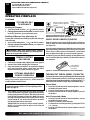
This appliance may be installed in an aftermarket,* permanently located, manufactured
(mobile) home, where not prohibited by local codes.
This appliance is only for use with the type of gas indicated on the rating plate. This appliance
is not convertible for use with other gases.
* Aftermarket: Completion of sale, not for purpose of resale, from the manufacturer
Thermostat Models:
CDCFTN, CDCFTP,
VDCFTN, VDCFTP,
FDCFTN, FDCFTP
Remote-Ready Models:
VDCFRN, VDCFRP,
FDCFRN, FDCFRP
Shown with Optional
Cabinet Mantel/Hearth
Base Accessory

111244-01A
For more information, visit www.desatech.com
For more information, visit www.desatech.com
2
WARNING: Do not use a blower insert, heat
exchanger insert, or other accessory not approved
for use with this fireplace.
WARNING: Do not allow fans to blow directly into
the fireplace. Avoid any drafts that alter burner flame
patterns. Ceiling fans can create drafts that alter
burner flame patterns. Altered burner patterns can
cause sooting.
Due to high temperatures, the appliance should be
located out of traffic and away from furniture and
draperies.
Do not place clothing or other flammable material on
or near the appliance. Never place any objects on
the heater.
Fireplace front and screen become very hot when
running heater. Keep children and adults away from
hot surfaces to avoid burns or clothing ignition.
Fireplace will remain hot for a time after shutdown.
Allow surfaces to cool before touching.
Carefully supervise young children when they are in
the room with fireplace. When using the hand-held
remote accessory (Remote-Ready Models Only), keep
selector switch in the OFF position to prevent chil-
dren from turning on burners with remote.
You must operate this fireplace with the fireplace
screen in place. Make sure fireplace screen is closed
before running fireplace.
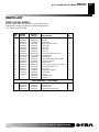
TABLE OF CONTENTS
SAFETY INFORMATION ............................................................ 2
PRODUCT IDENTIFICATION ..................................................... 3
OPTIONAL REMOTE CONTROL ACCESSORIES .................... 4
LOCAL CODES........................................................................... 4
PRODUCT FEATURES .............................................................. 4
UNPACKING ............................................................................... 4
HOOD ASSEMBLY ..................................................................... 4
AIR FOR COMBUSTION AND VENTILATION ........................... 5
INSTALLATION ........................................................................... 7
OPERATING FIREPLACE ........................................................ 19
INSPECTING BURNERS.......................................................... 24
SAFETY INFORMATION
DANGER: Carbon monoxide poisoning may lead
to death!
Carbon Monoxide Poisoning: Early signs of carbon monoxide
poisoning resemble the flu, with headaches, dizziness, or nausea.
If you have these signs, the fireplace may not be working properly.
Get fresh air at once! Have fireplace serviced. Some people are
more affected by carbon monoxide than others. These include
pregnant women, people with heart or lung disease or anemia,
those under the influence of alcohol, and those at high altitudes.
Natural and Propane/LP Gas: Natural and propane/LP gases are
odorless. An odor-making agent is added to the gas. The odor
helps you detect a gas leak. However, the odor added to the gas can
fade. Gas may be present even though no odor exists.
Make certain you read and understand all warnings. Keep this
manual for reference. It is your guide to safe and proper operation
of this fireplace.
WARNINGS
IMPORTANT: Read this owner’s manual carefully and
completely before trying to assemble, operate, or ser-
vice this fireplace. Improper use of this fireplace can
cause serious injury or death from burns, fire, explo-
sion, electrical shock, and carbon monoxide poisoning.
WARNING: Any change to this fireplace or its
controls can be dangerous.
TABLE OF CONTENTS
SAFETY INFORMATION
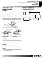
CLEANING AND MAINTENANCE ............................................ 24
WIRING DIAGRAM ................................................................... 25
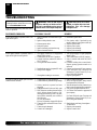
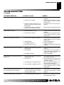
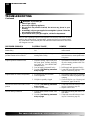
TROUBLESHOOTING .............................................................. 26
SPECIFICATIONS .................................................................... 29
SERVICE HINTS....................................................................... 29
TECHNICAL SERVICE ............................................................. 29
REPLACEMENT PARTS .......................................................... 29
ILLUSTRATED PARTS BREAKDOWN AND PARTS LIST ....... 30
ACCESSORIES ........................................................................ 36
OWNER’S REGISTRATION FORM.......................................... 39
WARNING: This product contains and/or generates
chemicals known to the State of California to cause
cancer or birth defects, or other reproductive harm.

111244-01A
For more information, visit www.desatech.com
For more information, visit www.desatech.com
3
3
SAFETY INFORMATION
Continued
SAFETY INFORMATION
PRODUCT IDENTIFICATION
1. This appliance is only for use with the type of gas indicated on
the rating plate. This appliance is not convertible for use with
other gases.
2. Do not place propane/LP supply tank(s) inside any structure.
Locate propane/LP supply tank(s) outdoors.
3. If you smell gas
• shut off gas supply
• do not try to light any appliance
• do not touch any electrical switch; do not use any phone in
your building
• immediately call your gas supplier from a neighbor’s phone.
Follow the gas supplier’s instructions
• if you cannot reach your gas supplier, call the fire department
4. This fireplace shall not be installed in a bathroom. Remote-
Ready Models shall not be installed in a bedroom.
5. Do not use this fireplace as a wood-burning fireplace. Use only
the logs provided with the fireplace.
6. Do not add extra logs or ornaments such as pine cones, ver-
miculite, or rock wool. Using these added items can cause soot-
ing. Do not add lava rock around base. Rock and debris could
fall into the control area of fireplace.
7. This fireplace is designed to be smokeless. If logs ever appear
to smoke, turn off fireplace and call a qualified service person.
Note:
During initial operation, slight smoking could occur due
to log curing and fireplace burning manufacturing residues.
8. To prevent the creation of soot, follow the instructions in Clean-
ing and Maintenance, pages 24 and 25.
9. Before using furniture polish, wax, carpet cleaner, or similar
products, turn fireplace off. If heated, the vapors from these
products may create a white powder residue within burner box
or on adjacent walls or furniture.
10. This fireplace needs fresh air ventilation to run properly. This
fireplace has an Oxygen Depletion Sensing (ODS) safety
shutoff system. The ODS shuts down the fireplace if not enough
fresh air is available. See Air for Combustion and Ventilation,
pages 5 through 7. If fireplace keeps shutting off, see Trouble-
shooting, pages 26 through 28.
11. Do not run fireplace
• where flammable liquids or vapors are used or stored.
• under dusty conditions.
12. Do not use this fireplace to cook food or burn paper or other
objects.
13. Never place any objects in the fireplace or on logs.
14. Do not use fireplace if any part has been under water. Immedi-
ately call a qualified service technician to inspect the room
fireplace and to replace any part of the control system and any
gas control which has been under water.
PRODUCT IDENTIFICATION
15. Turn off and unplug fireplace and let cool before servicing. Only
a qualified service person should service and repair fireplace.
16. Operating fireplace above elevations of 4,500 feet could cause
pilot outage.
17. Do not operate fireplace if log is broken. Do not operate fire-
place if log is chipped (dime-sized or larger).
18. To prevent performance problems, do not use propane/LP fuel
tank of less than 100 lbs. capacity.
19. Provide adequate clearances around air openings.
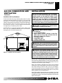
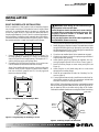
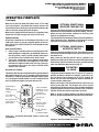
Ignitor Button
Screen
Fireplace
Cabinet
Log
Control Knob
Figure 1 - Vent-Free Compact Dual Flame
Fireplace
O
F
F
P
I
L
O
T
O
N
H
I
L
O
Hood
Fireplace
Cabinet
Logs
Ignitor Button
Remote
Control
(Optional)
Control
Knob
Keep the appliance area clear and free from combus-
tible materials, gasoline, and other flammable vapors
and liquids.
Hood

111244-01A
For more information, visit www.desatech.com
For more information, visit www.desatech.com
4
LOCAL CODES
Install and use fireplace with care. Follow all local codes. In the
absence of local codes, use the latest edition of The National Fuel
Gas Code ANSI Z223.1/NFPA 54*.
*Available from:
American National Standards Institute, Inc.
1430 Broadway
New York, NY 10018
National Fire Protection Association, Inc.
Batterymarch Park
Quincy, MA 02269
OPTIONAL REMOTE CONTROL ACCESSORIES
LOCAL CODES
PRODUCT FEATURES
UNPACKING
HOOD ASSEMBLY
OPTIONAL REMOTE
CONTROL ACCESSORIES
(For Remote-Ready Models Only)
There are four optional remote controls that can be purchased
separately for Remote-Ready Models only:
• wall switch • hand-held ON/OFF remote
• wall thermostat • hand-held thermostat remote
See Accessories, pages 36 and 37.
PRODUCT FEATURES
SAFETY PILOT
This fireplace has a pilot with an Oxygen Depletion Sensing (ODS)
safety shutoff system. The ODS/pilot is a required feature for vent-free
room fireplaces. The ODS/pilot shuts off the fireplace if there is not
enough fresh air.
PIEZO IGNITION SYSTEM
This fireplace has a piezo ignitor. This system requires no matches,
batteries, or other sources to light fireplace.
THERMOSTATIC HEAT CONTROL FOR
THERMOSTAT-CONTROLLED MODELS
Thermostat-Controlled models have a thermostat sensing bulb and
a control valve. The thermostat will automatically modulate the heat
output to maintain a consistent room temperature. This results in
greater fireplace comfort. This can also result in lower gas bills.
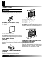
UNPACKING
1. Remove fireplace and hood from carton. Log is wrapped and
inside fireplace. Do not remove at this time.
2. Remove all protective packaging applied to fireplace for
shipment.
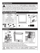
3. Make sure your fireplace includes one hardware packet.
4. Check fireplace for any shipping damage. If fireplace is dam-
aged, promptly inform dealer where you bought fireplace.
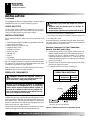
HOOD ASSEMBLY
Tools Required:
• Phillips screwdriver • slotted screwdriver
• 5/16" hex wrench • scissors
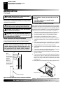
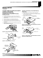
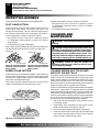
1. Lift fireplace screen up and pull out to remove (see Figure 2).
Set screen aside until installation has been completed.
2. Cut two plastic straps to remove the log from the firebox cavity.
Set log aside.
3. An optional blower is available. See Accessories, pages 36 and
37. Install optional blower now. Follow installation instruc-
tions provided with blower and see page 12 for Remote-Ready
Models or page 13 for Thermostat-Controlled Models.
4. Locate four black phillips sheet metal screws in hardware packet.
5. Slide hood between louver and firebox top and align screw holes.
6. Insert screws as shown in Figure 3. Tighten screws firmly.
Figure 2 - Removing and Installing Screen
WARNING: Always have screen in place before
operating fireplace. This prevents excessive tem-
peratures on fireplace surfaces.
WARNING: Failure to position the parts in accor-
dance with these diagrams or failure to use only parts
specifically approved with this fireplace may result in
property damage or personal injury.
Screen
Shoulder Screw
Figure 3 - Assembling Hood
Hood
Sheet Metal
Screws
Firebox Top
Louver

111244-01A
For more information, visit www.desatech.com
For more information, visit www.desatech.com
5
5
AIR FOR COMBUSTION AND VENTILATION
Providing Adequate Ventilation
Determining Fresh-Air Flow for Fireplace Location
AIR FOR COMBUSTION AND
VENTILATION
Today’s homes are built more energy efficient than ever. New mate-
rials, increased insulation, and new construction methods help reduce
heat loss in homes. Home owners weather strip and caulk around
windows and doors to keep the cold air out and the warm air in. During
heating months, home owners want their homes as airtight as possible.
While it is good to make your home energy efficient, your home
needs to breathe. Fresh air must enter your home. All fuel-burning
appliances need fresh air for proper combustion and ventilation.
Exhaust fans, fireplaces, clothes dryers, and fuel burning appliances
draw air from the house to operate. You must provide adequate fresh
air for these appliances. This will insure proper venting of vented
fuel-burning appliances.
WARNING: This fireplace shall not be installed in
a confined space or unusually tight construction
unless provisions are provided for adequate com-
bustion and ventilation air. Read the following in-
structions to insure proper fresh air for this and
other fuel-burning appliances in your home.
PROVIDING ADEQUATE VENTILATION
The following are excerpts from National Fuel Gas Code, ANSI
Z223.1/NFPA 54, Section 5.3, Air for Combustion and Ventilation.
All spaces in homes fall into one of the three following ventilation
classifications:
1. Unusually Tight Construction
2. Unconfined Space
3. Confined Space
The information on pages 5 through 7 will help you classify your
space and provide adequate ventilation.
Unusually Tight Construction
The air that leaks around doors and windows may provide enough
fresh air for combustion and ventilation. However, in buildings of
unusually tight construction, you must provide additional fresh air.
Unusually tight construction is defined as construction
where:
a. walls and ceilings exposed to the outside atmosphere
have a continuous water vapor retarder with a rating
of one perm (6 x 10
-11
kg per pa-sec-m
2
) or less with
openings gasketed or sealed
and
b. weather stripping has been added on openable win-
dows and doors
and
c. caulking or sealants are applied to areas such as
joints around window and door frames, between sole
plates and floors, between wall-ceiling joints, between
wall panels, at penetrations for plumbing, electrical,
and gas lines, and at other openings.
If your home meets all of these three criteria, you
must provide additional fresh air. See
Ventilation Air
From Outdoors
, page 8
.
If your home does not meet all of the three criteria above,
proceed to
Determining Fresh-Air Flow For Fireplace
Location,
below.
Confined and Unconfined Space
The National Fuel Gas Code, ANSI Z223.1/NFPA 54 defines a
confined space as a space whose volume is less than 50 cubic feet
per 1,000 Btu per hour (4.8 m
3
per kw) of the aggregate input rating
of all appliances installed in that space and an unconfined space as
a space whose volume is not less than 50 cubic feet per 1,000 Btu per
hour (4.8 m
3
per kw) of the aggregate input rating of all appliances
installed in that space. Rooms communicating directly with the
space in which the appliances are installed*, through openings not
furnished with doors, are considered a part of the unconfined space.
* Adjoining rooms are communicating only if there are doorless
passageways or ventilation grills between them.
DETERMINING FRESH-AIR FLOW FOR
FIREPLACE LOCATION
Determining if You Have a Confined or
Unconfined Space
Use this work sheet to determine if you have a confined or unconfined space.
Space: Includes the room in which you will install fireplace plus any adjoining
rooms with doorless passageways or ventilation grills between the rooms.
1. Determine the volume of the space (length x width x height).
Length x Width x Height =___________ cu. ft. (volume of space)
Example:
Space size 16 ft. (length) x 14 ft. (width) x 8 ft. (ceiling
height) = 1792 cu. ft. (volume of space)
If additional ventilation to adjoining room is supplied with grills or open-
ings, add the volume of these rooms to the total volume of the space.
2. Multiply the space volume by 20 to determine the maximum Btu/Hr
the space can support.
__________ (volume of space) x 20 = (Maximum Btu/Hr the space
can support)
Example:
1792 cu. ft. (volume of space) x 20 = 35,840 (maximum
Btu/Hr the space can support)

111244-01A
For more information, visit www.desatech.com
For more information, visit www.desatech.com
6
3. Add the Btu/Hr of all fuel burning appliances in the space.
Vent-free fireplace _____________ Btu/Hr
Gas water heater* _____________ Btu/Hr
Gas furnace _____________ Btu/Hr
Vented gas heater _____________ Btu/Hr
Gas fireplace logs _____________ Btu/Hr
Other gas appliances* + _____________ Btu/Hr
Total = _____________ Btu/Hr
* Do not include direct-vent gas appliances. Direct-vent draws com-
bustion air from the outdoors and vents to the outdoors.
Example:
Gas water heater _____________ Btu/Hr
Vent-free fireplace + _____________ Btu/Hr
Total = _____________ Btu/Hr
4. Compare the maximum Btu/Hr the space can support with the actual
amount of Btu/Hr used.
__________________ Btu/Hr (maximum the space can support)
__________________ Btu/Hr (actual amount of Btu/Hr used)
Example:
35,840 Btu/Hr (maximum the space can support)
40,000 Btu/Hr (actual amount of Btu/Hr used)
The space in the above example is a confined space because the actual Btu/
Hr used is more than the maximum Btu/Hr the space can support. You must
provide additional fresh air. Your options are as follows:
A. Rework worksheet, adding the space of an adjoining room. If the
extra space provides an unconfined space, remove door to adjoining
room or add ventilation grills between rooms. See Ventilation Air From
Inside Building.
B. Vent room directly to the outdoors. See Ventilation Air From Out-
doors, page 7.
C. Install a lower Btu/Hr fireplace, if lower Btu/Hr size makes room
unconfined.
If the actual Btu/Hr used is less than the maximum Btu/Hr the space can support,
the space is an unconfined space. You will need no additional fresh air ventilation.
AIR FOR COMBUSTION AND
VENTILATION
Continued
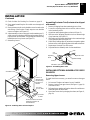
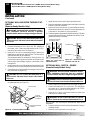
VENTILATION AIR
Ventilation Air From Inside Building
This fresh air would come from an adjoining unconfined space.
When ventilating to an adjoining unconfined space, you must
provide two permanent openings: one within 12" of the ceiling and
one within 12" of the floor on the wall connecting the two spaces
(see options 1 and 2, Figure 4). You can also remove door into
adjoining room (see option 3, Figure 4). Follow the National Fuel
Gas Code, ANSI Z223.1/NFPA 54, Section 5.3, Air for Combustion
and Ventilation for required size of ventilation grills or ducts.
Figure 4 - Ventilation Air from Inside Building
AIR FOR COMBUSTION AND VENTILATION
Determining Fresh-Air Flow for Fireplace Location (Cont.)
Ventilation Air
30,000
10,000
40,000
WARNING: If the area in which the fireplace may
be operated is smaller than that defined as an uncon-
fined space or if the building is of unusually tight
construction, provide adequate combustion and ven-
tilation air by one of the methods described in the
National Fuel Gas Code, ANSI Z223.1/NFPA 54 Sec-
tion 5.3
or applicable local codes
.
Or
Remove
Door into
Adjoining
Room,
Option
3
Ventilation Grills
Into Adjoining Room,
Option 2
Ventilation
Grills
Into Adjoining
Room,
Option 1
12"
12"

111244-01A
For more information, visit www.desatech.com
For more information, visit www.desatech.com
7
7
Figure 5 - Ventilation Air from Outdoors
Outlet
Air
Ventilated
Attic
Outlet
Air
Inlet
Air
Inlet Air
Ventilated
Crawl Space
To
Crawl
Space
To Attic
Ventilation Air From Outdoors
Provide extra fresh air by using ventilation grills or ducts. You must
provide two permanent openings: one within 12" of the ceiling and
one within 12" of the floor. Connect these items directly to the
outdoors or spaces open to the outdoors. These spaces include attics
and crawl spaces. Follow the National Fuel Gas Code, ANSI
Z223.1/NFPA 54, Section 5.3, Air for Combustion and Ventilation
for required size of ventilation grills or ducts.
IMPORTANT:
Do not provide openings for inlet or outlet air into
attic if attic has a thermostat-controlled power vent. Heated air
entering the attic will activate the power vent.
AIR FOR COMBUSTION AND
VENTILATION
Continued
CAUTION: This fireplace creates warm air cur-
rents. These currents move heat to wall surfaces next
to fireplace. Installing fireplace next to vinyl or cloth
wall coverings or operating fireplace where impurities
(such as, but not limited to, tobacco smoke, aromatic
candles, cleaning fluids, oil or kerosene lamps, etc.) in
the air exist, may discolor walls or cause odors.
INSTALLATION
IMPORTANT:
Vent-free fireplaces add moisture to the air. Although
this is beneficial, installing fireplace in rooms without enough ventila-
tion air may cause mildew to form from too much moisture. See Air for
Combustion and Ventilation, pages 5 through 7.
Note:
Your fireplace is designed to be used in zero clearance
installations. Wall or framing material can be placed directly against
any exterior surface on the rear, sides, or top of your fireplace,
except where standoff spacers are integrally attached. If standoff
spacers are attached to your fireplace, these spacers can be placed
directly against wall or framing materials.
Note:
When installing fireplace directly on carpeting, tile or other
combustible material, other than wood flooring, the fireplace shall
be installed on a metal or wood panel extending the full width and
depth of the fireplace.
WARNING: A qualified service person must in-
stall fireplace. Follow all local codes.
WARNING: Never install the fireplace
• in a bathroom
• in a recreational vehicle
• where curtains, furniture, clothing, or other flam-
mable objects are less than 36 inches from the
front, top, or sides of the fireplace
• as a fireplace insert
• in high traffic areas
• in windy or drafty areas
NOTICE: This heater is intended for use as supplemen-
tal heat. Use this heater along with your primary
heating system. Do not install this heater as your
primary heat source. If you have a central heating
system, you may run system’s circulating blower
while using heater. This will help circulate the heat
throughout the house. In the event of a power outage,
you can use this heater as your primary heat source.
WARNING: Never install the Remote-Ready Mod-
els in this manual in a bedroom. Any heating product
with a Btu/hr rating over 10,000 cannot be used in a
bedroom.
AIR FOR COMBUSTION AND VENTILATION INSTALLATION
Ventilation Air (Cont.)
INstallation

111244-01A
For more information, visit www.desatech.com
For more information, visit www.desatech.com
8
FIREPLACE CLEARANCES
WARNING: Maintain the minimum clearances
shown in Figure 6. If you can, provide greater clear-
ances from floor, ceiling, and joining wall.
NOTICE: If you install the fireplace in a bedroom
(Thermostat-Controlled Models only), some building
codes require that the fireplace/mantel system be
secured to (or within) a wall. You can position fire-
place in an optional cabinet or corner mantel. You can
also recess fireplace into the wall.
INSTALLATION
Continued
Use the dimensions shown for rough openings to create the easiest
installation (see Built-In Fireplace Installation, page 9).
CHECK GAS TYPE
Use the correct gas type (natural or propane/LP) for your unit. If
your gas supply is not correct, do not install fireplace. Call dealer
where you bought fireplace for proper type fireplace.
INSTALLATION ITEMS
Before installing fireplace, make sure you have the items listed
below.
• external regulator (supplied by installer, for propane/LP units only)
• piping (check local codes)
• sealant (resistant to propane/LP gas)
• equipment shutoff valve *
• test gauge connection*
• ground joint union
• sediment trap
• tee joint
• pipe wrench
* A CSA design-certified equipment shutoff valve with 1/8" NPT
tap is an acceptable alternative to test gauge connection. Purchase
the optional CSA design-certified equipment shutoff valve from
your dealer. See Accessories, pages 36 and 37.
Note:
If desired, purchase a four-sided brass trim kit for built-in
installations. See Accessories, pages 36 and 37.
If your fireplace is to be used with an optional mantel, the
installation instructions included with your mantel shows an CSA
approved method of attaching the fireplace/mantel system to a
wall.
IMPORTANT:
Only use optional cabinet or corner mantels
specified in this manual. Purchase the optional mantel from your
dealer (see Accessories, pages 36 and 37).
If your fireplace is to be recessed into the wall, see Built-In Fireplace
Installation on page 9 to secure your fireplace into the wall.
CAUTION: If you install the fireplace in a home
garage
• fireplace pilot and burner must be at least 18
inches above floor.
• locate fireplace where moving vehicle will not hit it.
For convenience and efficiency, install fireplace
• where there is easy access for operation, inspection, and service
• in coldest part of room
An optional blower kit is available from your dealer. See Accesso-
ries, pages 36 and 37. If planning to use blower, follow instructions
provided with blower for power source.
Minimum Clearances For Side Combustible
Material, Side Wall, and Ceiling
A. Clearances from the side of the fireplace cabinet to any com-
bustible material and wall should follow diagram in Figure 6.
Example:
The face of a mantel, bookshelf, etc. is made of
combustible material and protrudes 3
1
/2" from the wall. This
combustible material must be 4" from the side of the fireplace
opening (see Figure 6).
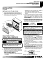
B. Clearances from the top of the fireplace opening to the ceiling
should not be less than 36 inches.
C. For mantel clearances, see Figure 10 on page 10.
Figure 6 - Minimum Clearance for Combustible to Wall
*Minimum 16 inches from Side Wall
*
Example
INSTALLATION
Check Gas Type
Installation Items
Fireplace Clearances
MINIMUM CLEARANCE TO
COMBUSTIBLE MATERIALS
Top Left and Bottom
Right Sides and Rear
36" 6" 0"

111244-01A
For more information, visit www.desatech.com
For more information, visit www.desatech.com
9
9
Actual Framing
Height 26" 26
7
/8"
Front Width 26
3
/4" 26
7
/8"
Depth 14
1
/4" 15
1
/4"
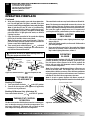
1. Frame in rough opening. Use dimensions shown in Figure 7 for
the rough opening. If installing in a corner, use dimensions
shown in Figure 8 for the rough opening. The height is 26
7
/8"
which is the same as the wall opening above.
2. If installing GA3450TA blower accessory, do so at this time.
Follow instructions included with blower accessory.
Note:
If not installing blower accessory, you may wish to run
electrical wiring to your fireplace for future blower installa-
tion (see Accessories, pages 36 and 37). Use only approved
three-wire electrical wiring.
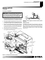
BUILT-IN FIREPLACE INSTALLATION
Built-in installation of this fireplace involves installing fireplace
into a framed-in enclosure. This makes the front of fireplace flush
with wall. An optional brass trim kit accessory is available (see
Accessories, pages 36 and 37). Brass trim will extend past sides of
fireplace approximately 1/2 inch. This will cover the rough edges of
the wall opening. If installing a built-in mantel above the fireplace,
you must follow the clearances shown in Figure 10, page 10. Follow
the instructions below to install the fireplace in this manner.
Note:
A qualified installer should make all electrical connections.
3. Install gas piping to fireplace location. This installation includes
an approved flexible gas line (if allowed by local codes) after
the equipment shutoff valve. The flexible gas line must be the
last item installed on the gas piping.
4. If you have not installed hood, follow instructions on page 4.
5. Carefully set fireplace in front of rough opening with back of
fireplace inside wall opening.
6. Attach flexible gas line to fireplace gas regulator. See Con-
necting Equipment Shutoff Valve to Heater Control, page 15.
7. Bend four nailing flanges on outer casing with pliers (see
Figure 9).
8. Attach fireplace to wall studs using nails or wood screws
through holes in nailing flange.
9. Check all gas connections for leaks. See Checking Gas Con-
nections, page 16.
10. If using optional brass trim kit, install the trim after final fin-
ishing and/or painting of wall. See instructions included with
brass trim accessory for attaching brass trim.
IMPORTANT:
When finishing your firebox, combustible materials
such as wall board, gypsum board, sheet rock, drywall, plywood, etc.
may be butted up next to the sides and top edge of the firebox.
Combustible materials should never overlap the firebox front facing.
INSTALLATION
Continued
Figure 8 - Rough Opening for Installing in Corner
Figure 7 - Rough Opening for Installing in Wall
43
5
/
16
"
30
5
/
8
"
61
1
/
4
"
26
7
/
8
"
Figure 9 - Attaching Fireplace to Wall Studs
WARNING: If pre-wiring, do not connect wiring to
any electrical source at this time.
Install fireplace electrical outlet and connect wiring
to outlet before connecting to electrical source. The
fireplace electrical outlet is included with the
GA3450TA blower accessory.
Only use the fireplace electrical outlet supplied with
the GA3450TA blower accessory.
Nailing
Flanges
Nails or
Wood
Screws
Wall Studs
INSTALLATION
Built-In Fireplace Installation
26
7
/
8
"
26
7
/
8
"
3/4" Off
The Floor
Minimum
15
1
/
4
"

111244-01A
For more information, visit www.desatech.com
For more information, visit www.desatech.com
10
INSTALLATION
Continued
Mantel Clearances for Built-In Installation
If placing mantel above built-in fireplace, you must meet minimum
clearance between mantel shelf and top of fireplace opening.
NOTICE: Surface temperatures of adjacent walls and
mantels become hot during operation. Walls and
mantels above the firebox may become hot to the
touch. If installed properly, these temperatures meet
the requirement of the national product standard.
Follow all minimum clearances shown in this manual.
Figure 10 - Minimum Mantel Clearances for Built-In Installation
Mantel Shelf
Side of Firebox
15"
18"
21"
23"
2
1
/
2
"
6"
8"
10"
Note:
All vertical
measurements
are from top of
fireplace
opening to
bottom of
mantel shelf. All
measurements
are in inches.
OPTIONAL MANTEL INSTALLATION
Note:
Refer to instructions provided with the mantel for assembly
instructions. Refer to the following instructions for system installa-
tion. Refer to instructions on page 4 for hood assembly. Blower
accessory should be installed if it is being used (see Installing
Optional Blower Accessory GA3450TA, pages 11 through 13).
1. Unscrew four screws that attach top louver to fireplace. Re-
move louver from fireplace and set aside (see Figure 11).
2. Place base assembly next to wall at installation location.
3. Place fireplace on wood base (see Figure 12, page 11).
4. Place mantel around fireplace on base (see Figure 12, page 11).
5. Assemble perimeter trim kit. See Assembling Perimeter Trim,
page 11.
6. Firmly snap perimeter trim kit on shoulder screws. Shoulder
screws are located on fireplace cabinet (see Figure 12, page 11).
7. Align perimeter trim kit for flush fit around opening.
8. Center mantel left to right on base making sure mantel is flush
against wall.
9. Use two 3" wood screws provided and attach base of fireplace
to wooden mantel base (see Figure 12, page 11).
10. Remove perimeter trim kit and mantel. Be careful not to dam-
age wall or mantel.
11. Cut an access hole in base to run flexible gas line to fireplace
(see Figure 12, page 11). Make sure to locate access hole so
mantel will cover it when installed.
Note:
You can secure
base to floor using wood screws. Countersink screw heads
and putty over.
12. Install gas line. See Connecting To Gas Supply, pages 14 and 15.
WARNING: Do not allow any combustible materi-
als to overlap the firebox front facing.
IMPORTANT:
Noncombustible materials such as brick, tile, etc.
may overlap the front facing, but should never cover any necessary
openings like louvered slots.
WARNING: Do not allow noncombustible materials
to cover any necessary openings like louvered slots.
WARNING: Use only noncombustible mortar or
adhesives when overlapping the front facing with
noncombustible facing material.
WARNING: Never modify or cover the louvered
slots on the front of the firebox.
NOTICE: If your installation does not meet the mini-
mum clearances shown, you must do one of the
following:
• raise the mantel to an acceptable height
• remove the mantel
INSTALLATION
Built-In Fireplace Installation (Cont.)
Optional Mantel Installation
Figure 11 - Removing Top Louver and Opening Bottom Louver
O
F
F
P
I
L
O
T
O
N
H
I
L
O
Top Louver
Bottom Louver

111244-01A
For more information, visit www.desatech.com
For more information, visit www.desatech.com
11
11
O
F
F
P
I
L
O
T
O
N
H
I
L
O
Figure 12 - Attaching Brass Trim to Fireplace
Shoulder Screw
Assembled
Brass Trim
Hole for 3" Wood Screw for
Attaching Fireplace to
Wooden Base
Hole for 3"
Wood Screw
for Attaching
Fireplace to
Mantel
Shoulder
Screws
13. Check for leaks. See Checking Gas Connections, page 16.
14. Place mantel around fireplace. Be careful not to damage wall
or mantel.
15. Place perimeter trim kit on the shoulder screws located on the
side and top of the fireplace. Firmly snap trim over shoulder
screws on fireplace (see Figure 12).
16. Adjust assembly to remove any gaps. Attach remaining two 3"
wood screws from hardware pack through openings inside of
fireplace sides into the mantel. The openings are located at top
behind the area for top louver (see Figure 12).
17. Reinstall top louver.
INSTALLATION
Continued
Gas Line
Access Hole
Mantel
Base
Assembling Perimeter Trim (Perimeter trim shipped
with mantel)
1. Remove packaging from three remaining pieces of trim.
2. Locate two adjusting plates with set screws, and two shims
in the hardware packet.
3. Align shim under adjusting plate as shown in Figure 13.
4. Slide one end of adjusting plate/shim in slot on mitered edge
of top brass trim (see Figure 13).
5. Slide other end of adjusting plate/shim in slot on mitered edge
of side perimeter trim (see Figure 13).
6. While firmly holding edges of perimeter trim together, tighten
both set screws on the adjusting plate with slotted screwdriver.
7. Repeat steps 1 through 6 for other corner.
8. Set perimeter trim assembly aside for later installation.
Figure 13 - Assembling Brass Trim
Side Brass Trim
Top Brass Trim
Mitered Edge
Shim
Set
Screws
Adjusting
Plate
Slot
INSTALLING OPTIONAL BLOWER ACCESSORY
GA3450TA
Removing Upper Louver
To install the blower accessory, you must first remove the upper
louver.
1. Lift screen off fireplace and remove log set if installed.
2. Remove 4 screws from upper louver (see Figure 11, page 10).
Save these screws.
3. Pull upper louver straight out from the cabinet. Be careful not to
scratch the paint. Set louver aside.
4. Open lower louver door by swinging door down (see Figure 11,
page 10).
INSTALLATION
Optional Mantel Installation (Cont.)
Installing Optioanl Blower Accessory GA3450TA

111244-01A
For more information, visit www.desatech.com
For more information, visit www.desatech.com
12
3
2
1
O
F
F
P
I
L
O
T
O
N
H
I
L
O
Installing Blower Accessory
Note:
If you are using a mantel with your fireplace, use the
following instructions. If your fireplace is built-in, see For Built-In
Installation, page 13.
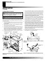
1. Install snap bushings found in blower kit into hole in left side
of outer casing and into one of the holes in rear of remote/
blower bracket.
2. Make sure the wire harness is firmly connected to the termi-
nals on the blower bracket assembly.
3. Note the wire locations on back of AUTO/OFF/ON switch. The
terminals on back of switch are numbered 1, 2, and 3. Carefully
remove red wire from terminal 3 and blue wire from terminal 1.
Black wire can remain on middle terminal 2 (see Figure 14).
4. Carefully disconnect green and white wires at their insulated
connectors (see Figure 15).
Figure 14 - Installing Blower Bracket Assembly (Remote-Ready
Unit Shown)
CAUTION: Label all wires prior to disconnection
when servicing controls. Wiring errors can cause
improper and dangerous operation.
CAUTION: Verify proper operation after servicing.
Wire
Harness
Blower Bracket
Assembly
Screw
Wire Harness
Switch
Baffle
Wiring Routing
Hole in Baffle
Switch
Plate
Blue
Red
Remote/Blower
Bracket
Power Cord
INSTALLATION
Continued
Figure 16 - Installing Switch Plate to Remote/Blower Bracket
Figure 15 - Wiring Diagram For Blower Accessory Standard
Installation
Red
Red
Fan Switch
(Auto/Off/On)
Blue
Blue
Thermostat
Switch
(N.O.)
Green
White
Green
White
On
110/115
V.A.C.
Blower
Motor
Black
Off
1
2
3
Auto
5. In top of the fireplace cabinet, locate the four mounting holes
on the outer casing. Align these four holes with those on the
blower bracket assembly. Attach blower bracket assembly to
the outer casing with 4 #10 screws provided (see Figure 14).
6. Route the wire harness through the hole in left side of baffle
and between firebox wrapper and outer casing.
7. Insert the 4 wire harnesses from behind the remote/blower
bracket through hole in rear of bracket with bushing and through
the left rectangular hole to front of fireplace (see Figure 14).
8. Reconnect red wire to switch position 3. Reconnect blue wire
to switch position 1. Reconnect green and white wires.
9. Install the switch plate on the remote/blower bracket with 2 #10
screws provided (see Figure 16). Route power cord out of the
cabinet by inserting it through the bushing on the outer casing
(see Figure 14). Plug fan kit into 120-Volt grounded power sup-
ply and test operation.
Note:
When switch is in the AUTO posi-
tion, the fan will start after the fireplace has run for a few mo-
ments. The fan will continue to run for several moments after the
fireplace has been turned off. When switch is in the ON position,
the fan will run until turned to OFF.
10. Reinstall upper louver beginning with bottom screws (see Fig-
ure 11, page 10). Close lower louver door.
Remote/Blower
Bracket
Switch
Plate
Screw
Black
Blower
Mounting
Holes
Lower Louver Door
INSTALLATION
Installing Optional Blower Accessory GA3450TA (Cont.)

111244-01A
For more information, visit www.desatech.com
For more information, visit www.desatech.com
13
13
3
2
1
O
F
F
P
I
L
O
T
O
N
H
I
L
O
Red
Red
Fan Switch
(Auto/Off/On)
Blue
Blue
Thermostat
Switch
(N.O.)
Green
White
Green
White
On
110/115
V.A.C.
Blower
Motor
Black
Off
1
2
3
Auto
Figure 17 - Installing Blower Bracket Assembly
Figure 18 - Wiring Diagram For Blower Accessory Built-In
Installation
INSTALLATION
Continued
INSTALLATION
Installing Blower Accessory GA3450TA (Cont.)
For Built-In Installation
WARNING: A licensed electrician must connect the
wiring harness to electrical supply following all local
codes. Electrician must provide a clamp on the box cover
to secure the wiring. Wiring should be routed through the
bushing in the hole on the outer casing of fireplace.
1. Install snap bushing from blower kit into one hole on rear of re-
mote/blower bracket (see Figure 17). The other hole is for a strain
relief clamp (not supplied) to secure incoming electrical supply.
2. Follow steps 2 through 6 in Installing Blower Accessory, page 12.
3. A licensed electrician must follow the wiring diagram to connect
incoming electrical supply to fan kit wiring harness (see Figure 18).
4. Plug power cord to outlet receptacle (not provided) as shown in
Figure 17. Wind extra cable of power cord and tie up with plas-
tic wire strap (see Figure 17). Set cable bundle between the re-
mote/blower bracket and outer casing, away from the burner.
5. Test to make sure blower is working properly.
6. Reinstall upper louver beginning with bottom screws (see Fig-
ure 11, page 10) and close lower louver.
Blower Bracket
Assembly
Screw
Wire Harness
Plastic Wire
Strap
Wire
Harness
Switch
Plate
Switch
Blue
Red
Power Cord
Lower Louver Door
Black
Extension Cord
Use extension cord if needed. The cord must have a three-prong,
grounding plug and a three-hole receptacle. Make sure cord is in good
shape. It must be heavy enough to carry the current needed. An
undersized cord will cause a drop in line voltage. This will result in
loss of power and overheating. Use a No. 16 AWG cord for lengths
less than 50 feet.
Outlet Receptacle
(not included)
Remote/ Blower
Bracket
Clamp Connector
(not included)

111244-01A
For more information, visit www.desatech.com
For more information, visit www.desatech.com
14
Installation must include an equipment shutoff valve, union, and
plugged 1/8" NPT tap. Locate NPT tap within reach for test gauge
hook up. NPT tap must be upstream from heater (see Figures 20).
IMPORTANT:
Install equipment shutoff valve in an accessible
location. The equipment shutoff valve is for turning on or shutting
off the gas to the appliance.
CAUTION: Use only new, black iron or steel pipe.
Internally-tinned copper tubing may be used in cer-
tain areas. Check your local codes. Use pipe of 1/2" or
greater diameter to allow proper gas volume to
fireplace. If pipe is too small, undue loss of volume
will occur.
* Purchase the optional CSA design-certified equipment shutoff valve from
your dealer. See Accessories, pages 38 and 39.
Figure 20 - Gas Connection
CSA Design-Certified
Equipment Shutoff Valve
With 1/8" NPT Tap*
3"
Minimum
Approved Flexible
Gas Line
Pipe Nipple Cap Tee Joint
PROPANE/LP
From External
Regulator (11"
W.C.** to 14"
W.C. Pressure)
NATURAL
From Gas Meter
(5" W.C.** to 10.5"
W.C. Pressure)
Sediment Trap
INSTALLATION
Continued
Propane/LP
Supply Tank
External Regulator
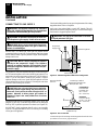
CONNECTING TO GAS SUPPLY
Figure 19 - External Regulator With Vent Pointing Down
Vent Pointing Down
WARNING: A qualified service person must con-
nect fireplace to gas supply. Follow all local codes.
CAUTION: Never connect propane/LP fireplace
directly to the propane/LP supply. This fireplace
requires an external regulator (not supplied). Install
the external regulator between the fireplace and pro-
pane/LP supply.
For propane/LP units, the installer must supply an external regula-
tor. The external regulator will reduce incoming gas pressure. You
must reduce incoming gas pressure to between 11 and 14 inches of
water. If you do not reduce incoming gas pressure, fireplace
regulator damage could occur. Install external regulator with the
vent pointing down as shown in Figure 19. Pointing the vent down
protects it from freezing rain or sleet.
WARNING: This appliance requires a 45° male flare
fitting 5/8"-18 UNF (Unified National Fine Thread) inlet
connection and the flexible gas line provided.
WARNING: Never connect natural gas fireplace to
private (non-utility) gas wells. This gas is commonly
known as wellhead gas.
INSTALLATION
Connecting to Gas Supply
IMPORTANT
: For natural gas, check gas line pressure before
connecting fireplace to gas line. Gas line pressure must be no greater
than 14 inches of water. If gas line pressure is higher, heater regulator
damage could occur.
Check your building codes for any special requirements for locating
equipment shutoff valve to fireplaces.
Apply pipe joint sealant lightly to male NPT threads. This will
prevent excess sealant from going into pipe. Excess sealant in pipe
could result in clogged fireplace valves.
WARNING: Use pipe joint sealant that is resistant
to liquid petroleum (LP) gas.

111244-01A
For more information, visit www.desatech.com
For more information, visit www.desatech.com
15
15
NOTICE: Most building codes do not permit con-
cealed gas connections. A flexible gas line is pro-
vided to allow accessibility from the fireplace (see
Figure 31). The flexible gas supply line connection to
the equipment shutoff valve should be accessible.
CONNECTING EQUIPMENT SHUTOFF VALVE
TO HEATER CONTROL
Installation Items Needed
• Phillips screwdriver
• sealant (resistant to propane/LP gas, not provided)
1. Open lower louver (see Figure 21).
Figure 21 - Flexible Gas Line Location (Remote-Ready Unit
Shown)
O
F
F
P
I
L
O
T
O
N
H
I
L
O
Lower
Louver
Flexible
Gas Line
INSTALLATION
Continued
INSTALLATION
Connecting To Gas Supply (Cont.)
Connecting Equipment Shutoff Valve To Heater Control
2. Route flexible gas line, included, from fireplace control to equip-
ment shutoff valve through side access holes in outer casing.
3. Apply pipe joint sealant lightly to male threads of gas connec-
tor attached to flexible gas line/equipment shutoff valve (see
Figure 22).
Figure 22 - Attaching Flexible Gas Line to Equipment Shutoff
Valve
Flexible Gas Line
from Fireplace
Gas Regulator
Provided With
Fireplace
To Gas Regulator (Thermostat-
Controlled Models) or Control
Valve (Remote-Ready Models)
Equipment
Shutoff Valve
PROPANE/LP
To External
Regulator
NATURAL
To Gas Supply
CAUTION: Avoid damage to regulator. Hold gas
regulator with wrench when connecting it to gas piping
and/or fittings (Thermostat-Controlled Models Only).
4. Check all gas connections for leaks. See Checking Gas Con-
nections, page 16. Feed flexible gas line into fireplace. Make
sure the entire flexible gas line is in fireplace.
➞
➞
CAUTION: Avoid damage to gas control. Hold gas
control with wrench when connecting it to gas piping
and/or fittings (Remote-Ready Models Only).
We recommend that you install a sediment trap in supply line as
shown in Figure 20, page 14. Locate sediment trap where it is within
reach for cleaning. Install in piping system between fuel supply and
heater. Locate sediment trap where trapped matter is not likely to
freeze. A sediment trap traps moisture and contaminants. This keeps
them from going into fireplace controls. If sediment trap is not
installed or is installed wrong, fireplace may not run properly.

111244-01A
For more information, visit www.desatech.com
For more information, visit www.desatech.com
16
Figure 24 - Checking Gas Joints (Propane/LP Only)
Propane/LP
Supply
Tank
Equipment
Shutoff Valve
Equipment
Shutoff Valve
Gas Meter
Figure 25 - Checking Gas Joints (Natural Gas Only)
3. Check all joints from gas meter to equipment shutoff valve for
natural gas or propane/LP supply to equipment shutoff valve
for propane/LP (see Figures 24 or 25). Apply noncorrosive
leak detection fluid to all joints. Bubbles forming show a leak.
4. Correct all leaks at once.
Pressure Testing Fireplace Gas Connections
1. Open equipment shutoff valve (see Figure 23).
2. Open main gas valve located on or near gas meter for natural
gas or open propane/LP supply tank valve.
3. Make sure control knob of fireplace is in the OFF position.
4. Check all joints from equipment shutoff valve to gas regulator
(Thermostat-Controlled Models), or to gas control valve (Remote-
Ready Models) (see Figures 24 or 25). Apply noncorrosive leak
detection fluid to all joints. Bubbles forming show a leak.
5. Correct all leaks at once.
6. Light fireplace (see Operating Fireplace, pages 19 through 23).
Check all other internal joints for leaks.
7. Turn off fireplace (see To Turn Off Gas to Appliance, page 20
for Thermostat-Controlled Models or page 22 for Remote-
Ready Models).
Gas Regulator or
Gas Control Valve
Gas Regulator or
Gas Control Valve
INSTALLATION
Continued
INSTALLATION
Checking Gas Connections
WARNING: Test all gas piping and connections,
internal and external to unit, for leaks after installing
or servicing. Correct all leaks at once.
WARNING: Never use an open flame to check for
a leak. Apply a noncorrosive leak detection fluid to
all joints. Bubbles forming show a leak. Correct all
leaks at once.
CAUTION: Make sure external regulator has been
installed between propane/LP supply and fireplace.
See guidelines under
Connecting to Gas Supply
,
pages 14 and 15.
Pressure Testing Gas Supply Piping system
Test Pressures In Excess Of 1/2 PSIG (3.5 kPa)
1. Disconnect appliance with its appliance main gas valve (control
valve) and equipment shutoff valve from gas supply piping sys-
tem. Pressures in excess of 1/2 psig will damage heater regulator.
2. Cap off open end of gas pipe where equipment shutoff valve
was connected.
3. Pressurize supply piping system by either opening propane/
LP supply tank valve for propane/LP gas or opening main gas
valve located on or near gas meter for natural gas, or using
compressed air.
4. Check all joints of gas supply piping system. Apply noncorrosive
leak detection fluid to all joints. Bubbles forming show a leak.
5. Correct all leaks at once.
6. Reconnect fireplace and equipment shutoff valve to gas sup-
ply. Check reconnected fittings for leaks.
Test Pressures Equal To or Less Than 1/2 PSIG (3.5 kPa)
1. Close equipment shutoff valve (see Figure 23).
2. Pressurize supply piping system by either opening propane/
LP supply tank valve for propane/LP gas or opening main gas
valve located on or near gas meter for natural gas, or using
compressed air.
CHECKING GAS CONNECTIONS
Figure 23 - Equipment Shutoff Valve
ON
POSITION
OFF
POSITION
Open
Closed
Equipment
Shutoff Valve

111244-01A
For more information, visit www.desatech.com
For more information, visit www.desatech.com
17
17
INSTALLATION
Continued
INSTALLATION
Optional Wireless Hand-Held Remote Control Accessories [Remote-Ready Models Only]
OPTIONAL WIRELESS HAND-HELD REMOTE
CONTROL ACCESSORIES
Remote-Ready Models Only
([C]GHRCB Series & [C]GHRCTB Series)
Installing Receiver
1. Disconnect wires from the control valve (see Figure 26) .
2. Locate the battery clip mounted on the back of the receiver
(see Figure 27).
3. Slide 9-volt battery (not included) through the clip.
4. Attach the terminal wires to the battery (see Figure 27).
5. Connect wires from remote receiver to control valve as shown
in Figure 28.
6. Install remote receiver unit onto remote/blower bracket using
screws provided (see Figure 28).
Figure 26 - Disconnecting Wires From Control Valve
Figure 27 - Attaching Battery to Receiver
Battery Clip
9-Volt Battery
Receiver
Terminal
Wires
O
F
F
P
I
L
O
T
O
N
H
I
L
O
Figure 28 - Installing Remote Receiver
Remote
Receiver
White Wire to
TH Terminal on
Control Valve
Red Wire to TPTH
Terminal on Control
Valve
Installing 9-Volt Battery in Hand-Held Remote
Control Unit
1. Remove battery cover on back of remote control unit.
2. Attach terminal wires to the battery (not included). Place bat-
tery into the battery housing.
3. Replace battery cover onto remote control unit.
Figure 29 - Installing Battery in Hand-Held Remote Control Unit
(GHRCB and CGHRCB Series)
Battery Cover
9-Volt
Battery
Terminal
Wires
Remote
Control Unit
Battery
Housing
Figure 30 - Installing Battery in Hand-Held Remote Control Unit
(GHRCTB and CGHRCTB Series)
Remote
Control Unit
Battery Cover
Terminal Wires
9-Volt
Battery
Battery
Housing

111244-01A
For more information, visit www.desatech.com
For more information, visit www.desatech.com
18
OPTIONAL WALL SWITCH - GWMS2
(Remote-Ready Models Only)
WARNING: Do not connect this switch to any electri-
cal source! Electrical shock and/or fire hazard will occur.
1. Remove jumper wire from control valve (see Figure 26, page 17).
2. Connect one terminal of 25 ft. wire to the “TH” terminal on
the control valve. Connect the other terminal to the "THTP"
terminal on the control valve. See Figure 31.
3.
Route the 25 ft. wire to a convenient location to mount your
wall switch (no outside walls).
WARNING: Do not connect the switch to a power
source. Electrical shock and/or fire hazard will occur.
WARNING: Read and follow installation instruc-
tions. Installation should be done by a qualified
installer familiar with low-voltage wiring procedures.
IMPORTANT:
The wire may be shortened but must not be
lengthened.
4. Connect one bare wire end to each of the terminals of the pro-
vided wall switch.
5. Install the wall switch and cover in the wall.
6. Connect one bare wire end to each terminal (“W” and “R”) of
the thermostat base (see Figure 33).
Figure 32 - Back View of
Thermostat Base
Feed wires through
rectangular slots
W
R
Figure 33 - Thermostat Base
Terminals “W” and “R”
Terminal “W”
Terminal “R”
INSTALLATION
Continued
OPTIONAL WALL MOUNTED THERMOSTAT -
GWMT1
(Remote-Ready Models Only)
WARNING: Do not connect this thermostat to any
electrical source! Electrical shock and/or fire hazard
will occur.
1.
Remove jumper wire from control valve (see Figure 26, page 17).
2. Connect one terminal of 25 ft. wire to the “TH” terminal on
the control valve. Connect the other terminal to the "THTP"
terminal on the control valve. See Figure 31.
3. Route the 25 ft. wire to a convenient location to mount your
thermostat (no outside wall).
IMPORTANT:
The wire may be
shortened but must not be lengthened.
The thermostat should be mounted 54" above the floor in a
location where there is good air circulation. Avoid heat sources
such as lamps, direct sunlight, fireplace, or heat and air condi-
tioning ducts.
4. Gently remove the cover of the thermostat from the base. Grasp
the sides of the cover firmly and pull to separate from the base.
5. Feed the electrical wires through the rectangular slots on each
side of the base (see Figure 32).
WARNING: Read and follow installation instruc-
tions. Installation should be done by a qualified
installer familiar with low-voltage wiring procedures.
Figure 31 - Connecting Wire Terminals
To Wall Thermostat
or Switch
To Wall
Thermostat
or Switch
Control Valve
WARNING: Do not connect the thermostat to a
power source. Electrical shock and/or a fire hazard
will occur.
INSTALLATION
Optional Wall Mounted Thermostat - GWMT1 (Remote-Ready Models Only)
Optional Wall Switch - GWMS2 (Remote-Ready Models Only)
7. Install the base onto the wall with the provided screws.
8. Move the temperature adjustment back and forth to insure the
bimetal is free from restrictions.
9. Replace the cover onto the base. (Upon installation, the ther-
mostat must be allowed to stabilize at room temperature for
a minimum of 30 minutes for proper operation).
10. Set the temperature adjustment to the desired setting. This ther-
mostat has been electronically calibrated at the factory. No ad-
justment or leveling is necessary.

111244-01A
For more information, visit www.desatech.com
For more information, visit www.desatech.com
19
19
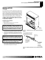
INSTALLING LOG SET AND SCREEN
1. Remove log packaging material and discard packaging. Gen-
tly place log over burner (see Figure 34). Do not allow log to
contact flame. If flame contacts log, soot will be created.
2. Reattach screen by placing the notches in the screen frame
over the shoulder screws and pushing down.
Log
Shoulder Screw
Screen
INSTALLATION
Continued
INSTALLATION
Installing Log Set and Screen
OPERATING FIREPLACE (THERMOSTAT-CONTROLLED MODELS)
For Your Safety Read Before Lighting
Lighting Instructions
Figure 34 - Installing Log and Screen
OPERATING FIREPLACE
WARNING: If you do not follow these instructions
exactly, a fire or explosion may result causing prop-
erty damage, personal injury or loss of life.
A. This appliance has a pilot which must be lighted by hand.
When lighting the pilot, follow these instructions exactly.
B. BEFORE LIGHTING smell all around the appliance area
for gas. Be sure to smell next to the floor because some gas
is heavier than air and will settle on the floor.
WHAT TO DO IF YOU SMELL GAS
• Do not try to light any appliance.
• Do not touch any electric switch; do not use any phone in
your building.
FOR YOUR SAFETY
READ BEFORE LIGHTING
THERMOSTAT-CONTROLLED MODELS
• Immediately call your gas supplier from a neighbor’s
phone. Follow the gas supplier’s instructions.
• If you cannot reach your gas supplier, call the fire de-
partment.
C. Use only your hand to push in or turn the gas control knob.
Never use tools. If the knob will not push in or turn by
hand, don’t try to repair it, call a qualified service techni-
cian or gas supplier. Force or attempted repair may result
in a fire or explosion.
D. Do not use this appliance if any part has been under water.
Immediately call a qualified service technician to inspect
the appliance and to replace any part of the control system
and any gas control which has been under water.
LIGHTING
INSTRUCTIONS
WARNING: You must operate this fireplace with
the screen in place. Make sure fireplace screen is
installed before running fireplace.
NOTICE: During initial operation of new fireplace,
burning logs will give off a paper-burning smell. Open
window to vent smell. Operate fireplace on HI position
to burn off odor. This will only last a few hours.
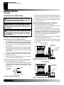
1. STOP! Read the safety information above.
2. Make sure equipment shutoff valve is fully open.
3. Turn control knob clockwise
Clockwise
to the OFF position.
4. Wait five (5) minutes to clear out any gas. Then smell for
gas, including near the floor. If you smell gas, STOP! Fol-
low “B” in the safety information in column 1. If you don’t
smell gas, go to the next step.
5. Turn control knob counterclockwise
C-clockwise
to the PI-
LOT position. Press in control knob for five (5) seconds
(see Figure 35).
Note:
You may be running this fireplace for the first time
after hooking up to gas supply. If so, the control knob may
need to be pressed in for 30 seconds or more. This will al-
low air to bleed from the gas system.
• If control knob does not pop out when released, contact
a qualified service person or gas supplier for repairs.
Figure 35 - Control Knob In The OFF Position
Ignitor
Button
Control Knob

111244-01A
For more information, visit www.desatech.com
For more information, visit www.desatech.com
20
TO TURN OFF GAS
TO APPLIANCE
1. Follow steps 1 through 5 under Lighting Instructions, begin-
ning on page 19.
2. With control knob pressed in, strike match. Hold match to
pilot until pilot lights.
3. Keep control knob pressed in for 30 seconds after lighting
pilot. After 30 seconds, release control knob. Now follow
step 8 under Lighting Instructions, column 1.
Shutting Off Fireplace
1. Turn control knob clockwise to the OFF position.
2. Turn off all electric power to the appliance (if applicable)
if service is to be performed.
Shutting Off Burners Only (pilot stays lit)
Turn control knob clockwise to the PILOT position.
THERMOSTAT CONTROL
OPERATION
The thermostat used on this fireplace senses the room tempera-
ture. At times the room may exceed the set temperature. If so,
the burner will shut off. The burner will cycle back on when
room temperature drops below the set temperature.
MANUAL LIGHTING
PROCEDURE
OPERATING
BLOWER
This blower has three settings: ON, OFF, and AUTO. In the ON
position, the blower will operate constantly. In the OFF posi-
tion, the blower will not operate. In the AUTO position, the
blower will start when the thermostat senses a sufficient in-
crease in firebox temperature.
Note:
Your fireplace and thermostat blower will not turn on
and off at the same time. The fireplace may run for several
minutes before the blower turns on. After the heater modulates
to the pilot position, the blower will continue to run. The blower
will shut off after the firebox temperature decreases.
Note:
It is safe to operate fireplace with blower turned off.
However, the blower helps distribute heated air from the fireplace.
Figure 38 - AUTO/OFF/ON Blower Switch
AUTO/OFF/ON Switch
CAUTION: Do not try to adjust heating levels by
using the equipment shutoff valve.
6. With control knob pressed in, press and release ignitor but-
ton. This will light pilot. The pilot is attached to the front
burner. If needed, keep pressing ignitor button until pilot lights.
Note:
If pilot does not stay lit, refer to Troubleshooting,
pages 26 through 28. Also, contact a qualified service per-
son or gas supplier for repairs. Until repairs are made, light
pilot with match. To light pilot with match, see Manual
Lighting Procedure.
7. Keep control knob pressed in for 30 seconds after lighting
pilot. After 30 seconds, release control knob.
Note:
If pilot goes out, repeat steps 3 through 7. This fire-
place has a safety interlock system. Wait one (1) minute for
system to reset before lighting pilot again.
8. Turn control knob counterclockwise to desired
heating level. The burner should light. Set control knob to
any heat level between HI and LO.
OPERATING FIREPLACE (THERMOSTAT-CONTROLLED MODELS)
Lighting Instructions (Cont.)
To Turn Gas Off To Appliance
Thermostat Control Operation
Manual Lighting Procedure
Operating Blower
Figure 36 - Natural Gas Pilot
Thermocouple
Ignitor Electrode
Pilot
Burner
Figure 37 -Propane/LP Gas
Pilot
Thermocouple
Ignitor
Electrode
Pilot
Burner
OPERATING FIREPLACE
Continued
The control knob can be set to any heat level between HI and LO.
Note:
The thermostat sensing bulb measures the air near the
fireplace cabinet. This may not always agree with room tem-
perature (depending on housing construction, installation loca-
tion, room size, open air temperatures, etc.). Frequent use of
your fireplace will let you determine your own comfort levels.
Page is loading ...
Page is loading ...
Page is loading ...
Page is loading ...
Page is loading ...
Page is loading ...
Page is loading ...
Page is loading ...
Page is loading ...
Page is loading ...
Page is loading ...
Page is loading ...
Page is loading ...
Page is loading ...
Page is loading ...
Page is loading ...
Page is loading ...
Page is loading ...
Page is loading ...
Page is loading ...
Page is loading ...
Page is loading ...
-
 1
1
-
 2
2
-
 3
3
-
 4
4
-
 5
5
-
 6
6
-
 7
7
-
 8
8
-
 9
9
-
 10
10
-
 11
11
-
 12
12
-
 13
13
-
 14
14
-
 15
15
-
 16
16
-
 17
17
-
 18
18
-
 19
19
-
 20
20
-
 21
21
-
 22
22
-
 23
23
-
 24
24
-
 25
25
-
 26
26
-
 27
27
-
 28
28
-
 29
29
-
 30
30
-
 31
31
-
 32
32
-
 33
33
-
 34
34
-
 35
35
-
 36
36
-
 37
37
-
 38
38
-
 39
39
-
 40
40
-
 41
41
-
 42
42


Ask a question and I''ll find the answer in the document
Finding information in a document is now easier with AI
Related papers
Other documents
-
FMI GWMT1 Operating instructions
-
Vanguard Heating Indoor Fireplace WMH26TNB User manual
-
 Estate Design EFPMH23JG Operating instructions
-
-
-
-
-
-
-
