Nortel 553-3901-200 User manual
- Category
- Networking
- Type
- User manual

Meridian 1
ISDN Basic Rate Interface
Installation
Document Number: 553-3901-200
Document Release: Standard 7.00
Date: January 2002
Year Publish FCC TM
Copyright © 1992–2002 Nortel Networks
All Rights Reserved
Printed in Canada
Information is subject to change without notice. Nortel Networks reserves the right to make changes in design
or components as progress in engineering and manufacturing may warrant. This equipment has been tested
and found to comply with the limits for a Class A digital device pursuant to Part 15 of the FCC rules, and the
radio interference regulations of Industry Canada. These limits are designed to provide reasonable protection
against harmful interference when the equipment is operated in a commercial environment. This equipment
generates, uses and can radiate radio frequency energy, and if not installed and used in accordance with the
instruction manual, may cause harmful interference to radio communications. Operation of this equipment in a
residential area is likely to cause harmful interference in which case the user will be required to correct the
interference at their own expense.
SL-1 and Meridian 1 are trademark of Nortel Networks.


Page 3 of 46
ISDN Basic Rate Interface Installation
4
Revision history
January 2002
Standard 7.00. This document is up-issued to to include content changes for
Meridian 1 Release 25.40.
April 2000
Standard 6.00. This is a global document and is up-issued for X11 Release
25.0x. Document changes include removal of: redundant content; references
to equipment types except Options 11C, 51C, 61C, and 81C; and references
to previous software releases.
October 1997
Issue 5.00 released as Standard for Generic X11 Release 23.00
August 1996
Issue 4.00 released as Standard for Generic X11 Release 22.0x.
December 1995
Issue 3.00 released as Standard for Generic X11 Release 21.1x.
Note: No issue 2.00 was published.
December 1994
Issue 1.00 released as Standard for Generic X11 Release 20.00
July 1994
Standard version released for Generic X11 Release 19.00
July 1993
Standard version released for Generic X11 Release 18.00


Page 7 of 46
ISDN Basic Rate Interface Installation
8
About this document
This document applies to Meridian 1 Internet Enabled systems.
This document is a global document. Contact your system supplier or your
Nortel Networks representative to verify that the hardware and software
described is supported in your area.
Note 1: For Option 11C specific information, refer to Option 11C Basic
Rate Interface (BRI) (553-3011-311).
Note 2: ISDN BRI trunking is not available in North America.


Page 9 of 46
ISDN Basic Rate Interface Installation
12
Preinstallation preparation
Contents
The following are the topics in this section:
Prepare the site . . . . . . . . . . . . . . . . . . . . . . . . . . . . . . . . . . . . . . . . . . . 9
Unpack and inspect . . . . . . . . . . . . . . . . . . . . . . . . . . . . . . . . . . . . . . . . 10
Take inventory . .. . . . . . . . . . . . . . . . . . . . . . . . . . . . . . . . . . . . . . . . . . 11
Reference list
The following are the references in this section:
• Installation Planning (553-3001-120)
• System Engineering (553-3001-151)
• Power Engineering (553-3001-152)
• System Installation Procedures (553-3001-210)
• ISDN Basic Rate Interface: Product Description (553-3901-100)
Prepare the site
When installing a system, address the following factors.
• environmental
•structural
•electrical
Refer to the following documents for more information.
• Installation Planning (553-3001-120)

Page 10 of 46 Preinstallation preparation
553-3901-200 Standard 7.00 January 2002
• System Engineering (553-3001-151)
• Power Engineering (553-3001-152)
After the site has been planned, the following items must be completed prior
to ISDN BRI installation.
• Wire the building between ISDN BRI terminal locations and the
distribution frame. Refer to the “Engineering guidelines” section of
ISDN Basic Rate Interface: Product Description (553-3901-100) for
wiring specifications and guidelines. For the location of the terminals
and the distribution frame, use the Building Cable Plan developed
according to instructions in the “Planning the site” section in Installation
Planning (553-3001-120).
• Install any IPE or Network Modules needed to house ISDN BRI cards as
determined in “Engineering guidelines” of ISDN Basic Rate Interface:
Product Description (553-3901-100). Refer to System Installation
Procedures (553-3001-210) for a description of how to install the
modules.
Unpack and inspect
ISDN BRI cards and external communication cables are shipped in separate
packages. To unpack them, follow the general precautions recommended by
computer and telephone equipment manufacturers.
• Remove items that generate static charge from the installation site.
• If the installation site is carpeted, spray it with an antistatic spray.
• Ground yourself before handling any equipment.
• Carefully remove the equipment from its packaging. Do not puncture or
tear the containers. Use scissors or a utility knife.
• Inspect the equipment for obvious faults or damage. Report any damaged
component to your sales representative and the carrier who delivered the
equipment.
• When unpacking the circuit cards, hold them only by their
non-conductor edges. Do not touch connector pins or components.

Preinstallation preparation Page 11 of 46
ISDN Basic Rate Interface Installation
• Keep the circuit cards in their antistatic bags until you are ready to install
them.
• Do not stack the plug-in cards on top of each other. This can damage the
components and the printed circuits on the cards.
Take inventory
After unpacking, verify that all the equipment necessary is at the site before
installation begins. Check the equipment received against the shipping
documents. Note any shortages and report them to your sales representative.


Page 13 of 46
ISDN Basic Rate Interface Installation
46
Install ISDN BRI hardware
Contents
The following are the topics in this section:
Install ISDN BRI hardware for line applications . . . . . . . . . . . . . . . . . 14
Select the card slots . . . . . . . . . . . . . . . . . . . . . . . . . . . . . . . . . . . . . 15
Remove the module cover for card installation . . . . . . . . . . . . . . . . 19
Install the MISP . . . . . . . . . . . . . . . . . . . . . . . . . . . . . . . . . . . . . . . . 20
Remove the MISP . .. . . . . . . . . . . . . . . . . . . . . . . . . . . . . . . . . . . . . 21
Install the BRSC, SILC and UILC . . . . . . . . . . . . . . . . . . . . . . . . . . 21
Remove the BRSC, SILC and UILC . . . . . . . . . . . . . . . . . . . . . . . . 22
Connect ISDN BRI terminals to Meridian 1 . . . . . . . . . . . . . . . . . . 22
Install ISDN BRI hardware for trunk applications . . . . . . . . . . . . . . . . 38
Select the card slots . . . . . . . . . . . . . . . . . . . . . . . . . . . . . . . . . . . . . 38
Remove the module cover for card installation . . . . . . . . . . . . . . . . 38
Install the MISP . . . . . . . . . . . . . . . . . . . . . . . . . . . . . . . . . . . . . . . . 38
Install the clock reference on the SILC . . . . . . . . . . . . . . . . . . . . . . 38
Install the SILC and the UILC . . . . . . . . . . . . . . . . . . . . . . . . . . . . . 42
Connect Meridian 1 to the Main Distribution Frame (MDF) . .. . . . 42
Cross-connect the Main Distribution Frame (MDF) . . . . . . . . . . . . 42
Card location forms . . . . . . . . . . . . . . . . . . . . . . . . . . . . . . . . . . . . . 44
Reference list
The following are the references in this section:
• Meridian Communications Unit and Meridian Communications
Adapter: Description, Installation, Administration, Operation
(553-2731-109)

Page 14 of 46 Install ISDN BRI hardware
553-3901-200 Standard 7.00 January 2002
• ISDN PRI: Installation (553-2901-201)
• System Installation Procedures (553-3001-210)
• ISDN Basic Rate Interface: Product Description (553-3901-100)
• ISDN Basic Rate Interface: Administration (553-3901-300)
Install ISDN BRI hardware for line applications
The following lists the procedures for installing ISDN BRI hardware for line
applications. Meridian 1 must already be installed and operating according to
the instructions in System Installation Procedures (553-3001-210) before
performing these procedures.
For a successful installation, perform these procedures in the order listed
below:
1 Select the card slots where the ISDN BRI cards will be located
2 Remove the module cover for card installation
3 Install the MISPs
4 Install the SILCs and/or UILCs or BRSCs
5 Connect ISDN BRI terminals. This procedure comprises the following:
— connect the Meridian 1 to the Main Distribution Frame (MDF)
— cross connect the MDF
— connect ISDN BRI terminals to the DSL
— initialize the ISDN BRI terminals.
—————————— End of Procedure ——————————

Install ISDN BRI hardware Page 15 of 46
ISDN Basic Rate Interface Installation
Select the card slots
To install ISDN BRI cards, perform the following steps:
1 Identify all the slots that can contain them. First identify the modules
with unused network and peripheral card slots and then remove the
covers from the identified modules. To identify the modules, use the
following Print Programs. Table 1 lists the modules that can house
ISDN BRI cards.
• LD 22 to print the system configuration and identify unused
network card slots to install MISPs
• LD 20 to list unused IPE card slots to install SILCs, UILCs and
BRSCs
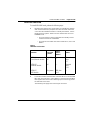
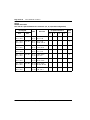
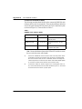
Table 1
ISDN BRI card location
2 Locate the card slots in the Meridian 1 modules which can house ISDN
BRI cards. Group all SILCs, UILCs, BRSCs, superloops and the MISP
that supports them in the same network group to avoid using junctors
for dedicated connections.
The following rules apply when selecting the card slots:
Modules
Supported
Systems
SILCs,
UILCs,
BRSCs
MISPs
NT5D21
Core/Network Module
51C, 61C,
81C
—
Network
slots
0-7
NT8D35
Network Module
81C
—
Network
slots
5-12
NT8D37
IPE Module
All systems IPE slots
0-15
—

Page 16 of 46 Install ISDN BRI hardware
553-3901-200 Standard 7.00 January 2002
MISPs
• MISPs are inserted into the CE/Network Module for options 51C and
61C, and the Network Module for options 81C. Refer to the LD 22
printout to identify modules with unused network card slots and to
Table 1 for the card slots in these modules that can house MISPs.
• An MISP cannot share network loop addresses with a Superloop
Network Card in options 51C, 61C, and 81C. The MISP requires two
network loop addresses and one network card slot.
• An MISP supports a maximum of eight BRSCs and two line cards.
• An MISP supports a set of four SILCs or UILCs when not supporting a
BRSC.
• An MISP can support both BRSCs and SILCs or UILCs at the same time.
If it serves one BRSC, a MISP can also support three line cards. If it
supports two or more BRSCs, a MISP can also support two line cards.
BRSCs
• Install one BRSC per IPE module.
• With a BRSC configured, an IPE module can support a maximum of 15
line cards. These may be up to eight UILCs combined with any other
seven peripheral cards (including SILCs), or up to 15 SILCs.
SILCs/UILCs
• SILCs, UILCs and BRSCs are installed into the IPE card slots of the
CE/PE Module and/or the IPE Module for option 21E. They are installed
into the IPE Module for all other system options. Refer to the LD 20
printout to identify modules with unused peripheral card slots.

Install ISDN BRI hardware Page 17 of 46
ISDN Basic Rate Interface Installation
• In each module, install a maximum of 15 SILCs, or eight UILCs
combined with any other seven peripheral cards (including SILCs). If 15
SILCs are installed, the remaining slots in the module may contain a
BRSC, a UILCs or non-ISDN BRI cards that do not need the - 48 V
power supply of the IPE module (this restriction is due to power supply
limitations for the module). If 8 UILCs are used, you may install any
other card which could reside in the IPE module.
• Group all SILCs, UILCs, BRSCs and the MISP that supports them in the
same network group to avoid using junctors for dedicated connections.
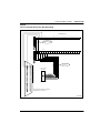
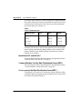
The figures that follow show typical module configurations.
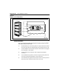
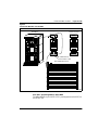
Figure 1 shows the NT8D35 Network module.
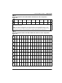
Figure 2 shows the NT8D37 IPE module.
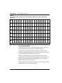
Figure 3 shows the NT5D21 Core/Network module.
Figure 1
NT8D35 Network module
CE Module Net
Common Equipment
3PE IGS 1 IGS 0 PS SLP
1234567891011121314
CE Pwr Sup SLP SLP SLP
Network Group
Shelf
553-3082
DCHI (5-13)
MSDL (5-13)
MISP
PRI/DTI (5-9)
SDI
CE Module Net
Common Equipment
3PE IGS 1 IGS 0 PS SLP
1234567891011121314
CE Pwr Sup
QPC441 3-Port Extender
QPC412 InterGroup Switch
QPC43 Peripheral Signaling
SLP SLP SLP
Network Group
Shelf
QPC412 InterGroup Switch
PRI/DTI or SDI
PRI/DTI
DCHI (5-13)
MSDL (5-13)
MISP
Network-type cards:
NT8D04 Superloop Net
QPC414 Network Card
NT8D17 Conference/TDS
PRI/DTI (5-9)
SDI
553-7692

Page 18 of 46 Install ISDN BRI hardware
553-3901-200 Standard 7.00 January 2002
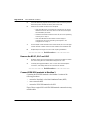
Figure 2
NT8D37 IPE module
Intelligent
Peripheral Equipment
Superloop
Shelf
IPEPE Module
PE Pwr Sup Rng Gen
0 2 3 4 5 6 7 Cont 9 11 12 13 15181410
Intelligent
Peripheral Equipment
Superloop
Shelf
IPEPE Module
PE Pwr Sup Rng Gen
Intelligent
line and trunk
cards
Intelligent
line and trunk
cards
NT8D01 Controller Card
0 2 3 4 5 6 7 Cont 9 11 12 13 15181410
553-7694

Install ISDN BRI hardware Page 19 of 46
ISDN Basic Rate Interface Installation
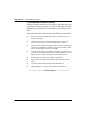
Figure 3
NT5D21 Core/Network module
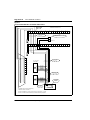
Remove the module cover for card installation
To remove the covers from Meridian 1 modules with unused card slots,
follow the procedure below. Refer to Figure 4.
1 Use a flat-blade screwdriver to unlock the left latch on the front of the
cover by turning the screw 1/4 turn clockwise.
2 Use a flat-blade screwdriver to unlock the right latch on the front of the
cover by turning the screw 1/4 turn counterclockwise.
3 While holding the cover so it does not fall off, slide the latches toward
the center of the cover.
4 Pull the cover toward you and lift it away from the module.
5 Place the cover in a safe place away from the working area to avoid
damaging it.
6 Repeat steps 1 through 5 for each cover requiring removal.
(No card should be inserted into this slot)
CNI
CNI
CNI
CE Pwr Sup
012 3 4 5 6 7 8 9 10 11 12 13 14 15 17
SLP SLP SLP PS 3PE CNI
Core/Net Module
Network Group CPU
Shelf
LRTN
FGND
SLP
NT8D17 Conference/TDS
NT8D04 Superloop Network Card
QPC414 Network Card
NT8D04 Superloop Network Card
NT8D04 Superloop Network Card
Dual InterGroup Switch Card
QPC43R Peripheral Signaling Card
Call Processor Card
NT5D61 IODU/C
16 18
NT5D21
553-6383
3-Port Extender Card
Net CoreCore/Net Module

Page 20 of 46 Install ISDN BRI hardware
553-3901-200 Standard 7.00 January 2002
Figure 4
Module cover locking latches
Install the MISP
Once covers have been removed and card slot locations selected for ISDN
BRI cards, install the MISP cards.
1 Hold the MISP by its card-locking devices. Squeeze the tabs to unlatch
the card-locking devices and lift the tabs out and away from the card.
2 Insert the MISP into the selected card slot of the module so it engages
the card guides in the module.
3 Slide the MISP into the module until it engages the backplane
connector.
4 Push the MISP firmly into the connector using the locking devices as
levers by pushing them toward the card's front panel.
5 Push the tabs firmly against the front panel of the card so they latch to
the front lip in the module and to the post on the card.
Turn to unlock
Slide to
unlatch cover
553
-
5458
Lock screw
S
liding Latch Knob
Turn to unlock
Slide to
unlatch cover
Meridian 1
553-7695
Page is loading ...
Page is loading ...
Page is loading ...
Page is loading ...
Page is loading ...
Page is loading ...
Page is loading ...
Page is loading ...
Page is loading ...
Page is loading ...
Page is loading ...
Page is loading ...
Page is loading ...
Page is loading ...
Page is loading ...
Page is loading ...
Page is loading ...
Page is loading ...
Page is loading ...
Page is loading ...
Page is loading ...
Page is loading ...
Page is loading ...
Page is loading ...
Page is loading ...
Page is loading ...
Page is loading ...
Page is loading ...
-
 1
1
-
 2
2
-
 3
3
-
 4
4
-
 5
5
-
 6
6
-
 7
7
-
 8
8
-
 9
9
-
 10
10
-
 11
11
-
 12
12
-
 13
13
-
 14
14
-
 15
15
-
 16
16
-
 17
17
-
 18
18
-
 19
19
-
 20
20
-
 21
21
-
 22
22
-
 23
23
-
 24
24
-
 25
25
-
 26
26
-
 27
27
-
 28
28
-
 29
29
-
 30
30
-
 31
31
-
 32
32
-
 33
33
-
 34
34
-
 35
35
-
 36
36
-
 37
37
-
 38
38
-
 39
39
-
 40
40
-
 41
41
-
 42
42
-
 43
43
-
 44
44
-
 45
45
-
 46
46
-
 47
47
-
 48
48


Nortel 553-3901-200 User manual
- Category
- Networking
- Type
- User manual
Ask a question and I''ll find the answer in the document
Finding information in a document is now easier with AI
Related papers
-
Nortel Networks NN43001-318 User manual
-
Nortel Networks Communication Server 1000 User manual
-
Nortel Networks Succession 1000M User manual
-
-
-
Nortel Networks Succession 1000M User manual
-
-
Nortel AA1419042 Datasheet
-
-
Nortel 9115 Release note
Other documents
-
Lewis Hyman 9602028E User manual
-
 Meridian America 61 User manual
-
 DeckWise IPE-SEAL-1-QT Operating instructions
-
Meridian 11C User manual
-
-
-
 Meridian America Link/Customer Controlled Routing User manual
-
-
-


