Page is loading ...

BB14 Series
Intercept
®
Back Box
Installation/
Operation Manual
C454M-C (1/98)
Pelco • 3500 Pelco Way • Clovis, CA 93612-5699 USA • www.pelco.com
In North America and Canada: Tel (800) 289-9100 or FAX (800) 289-9150
International Customers: Tel (1-559) 292-1981 or FAX (1-559) 348-1120

2 Pelco Manual C454M-C (1/98)
CONTENTS
Section Page
1.0 GENERAL .................................................................................................. 5
1.1 IMPORTANT SAFEGUARDS AND WARNINGS ............................... 5
1.2 UNPACKING INSTRUCTIONS .......................................................... 6
1.3 RECOMMENDED TOOLS ................................................................. 6
2.0 DESCRIPTION ..........................................................................................7
2.1 MODELS ............................................................................................ 7
3.0 INSTALLATION ..........................................................................................9
3.1 MOUNTING ....................................................................................... 9
3.1.1 Suspended Ceiling Mounting ................................................. 9
3.1.2 Hard Ceiling Mounting .......................................................... 10
3.1.2.1 Optional Backup Plate Installation ......................... 10
3.1.3 Pendant Mounting ................................................................. 11
3.2 WIRING INSTRUCTIONS ................................................................. 12
3.2.1 On-Board Receiver/Driver .................................................... 12
3.2.2 Hard-Wire or Remote Receiver/Driver .................................. 17
3.2.3 Heater/Blower Kit Field Installation ....................................... 20
3.3 DOME DRIVE INSTALLATION ......................................................... 20
4.0 EXPLODED ASSEMBLY DIAGRAMS ...................................................... 21
5.0 SPECIFICATIONS .................................................................................... 26
6.0 WARRANTY AND RETURN INFORMATION ........................................... 28

Pelco Manual C454M-C (1/98) 3
REVISION HISTORY
Manual # Date Comments
C454M — Original version.
C454M-A 6/95 Revised to incorporate B.O.M. quantity changes as per
ECO# 94-445. Added 4-position terminal block information
as per ECO# 94-042. Incorporated new “Front” labeling
to B.O.M. as per ECO# 94-192. Updated manual to new
style standards. Added manual revision history.
6/23/95 Addendum. Incorporated new fuse and fuse holder into
wiring diagrams and exploded view diagram as per
ECO# 95-063.
2/27/96 Addendum. Section 5.0 Mechanical Parts List revised.
C454M-B 4/96 Rev. B. Added Section 3.4.2.1 and Figure 16 per ECO#
96-061. Changed heater specifications.
C454M-C 1/98 Changed manual to new format and manual pagination.
Reduced number of models. Revised installation
instructions. Updated exploded assembly diagrams and
parts lists.
LIST OF ILLUSTRATIONS
Figure Page
1“T-Bar” Clip Installation .......................................................................9
2 Backup Plate Installation ................................................................... 11
3 24 VAC Back Box Wiring Diagram
(for Dome Drives with Integral Receiver/Driver) ................................ 14
4 120 VAC Back Box Wiring Diagram
(for Dome Drives with Integral Receiver/Driver) ................................ 15
5 230 VAC Back Box Wiring Diagram
(for Dome Drives with Integral Receiver/Driver) ................................ 16
6Wiring Diagram, Hard-Wire Control with Heater ............................... 18
7Wiring Diagram, Hard-Wire Control without Heater ..........................19
8 Suspended Ceiling Back Box Exploded Assembly Diagram ............. 21
9 Hard Ceiling Back Box Exploded Assembly Diagram .......................22
10 Pendant Back Box Exploded Assembly Diagram .............................. 23
11 Back Plate Exploded Assembly Diagram .......................................... 24
12 Suspended/Hard Ceiling Dimension Drawings ................................. 27
13 Pendant-Mount Dimension Drawing ................................................. 27
LIST OF TABLES
Table Page
A Video Coaxial Cable Requirements ................................................. 13
B 24 VAC Wiring Distances ..................................................................13
C Suspended Ceiling Back Box Exploded Assembly Parts List ........... 21
D Hard Ceiling Back Box Exploded Assembly Parts List ...................... 22
E Pendant Back Box Exploded Assembly Part List .............................. 23
F Back Plate Exploded Assembly Parts List (Figure 11) ...................... 25

4 Pelco Manual C454M-C (1/98)
(This page intentionally left blank.)

Pelco Manual C454M-C (1/98) 5
Please thoroughly familiarize yourself with the information
in this manual prior to installation and operation.
1.0 GENERAL
1.1 IMPORTANT SAFEGUARDS AND WARNINGS
Prior to installation and use of this product, the following WARNINGS should be
observed.
1. Installation and servicing should only be done by Qualified Service Personnel
and conform to all Local codes.
2. Unless the unit is specifically marked as a NEMA Type 3, 3R, 3S, 4, 4X, 6, or
6P enclosure, it is designed for indoor use only and it must not be installed
where exposed to rain and moisture.
3. Only use replacement parts recommended by Pelco.
4. After replacement/repair of this unit’s electrical components, conduct a resis-
tance measurement between line and exposed parts to verify the exposed
parts have not been connected to line circuitry.
5. The installation method and materials should be capable of supporting four
(4) times the weight of the enclosure, pan/tilt, camera and lens combination.
The product and/or manual may bear the following marks:
This symbol indicates that dangerous voltage constituting a
risk of electric shock is present within this unit.
This symbol indicates that there are important operating and
maintenance instructions in the literature accompanying this
unit.
CAUTION:
RISK OF
ELECTRIC SHOCK.
DO NOT OPEN.
CAUTION:
TO REDUCE THE RISK OF ELECTRICAL SHOCK,
DO NOT REMOVE COVER. NO USER-
SERVICEABLE PARTS INSIDE. REFER SERVICING
TO QUALIFIED SERVICE PERSONNEL.

6 Pelco Manual C454M-C (1/98)
1.2 UNPACKING INSTRUCTIONS
Unpack and inspect all parts carefully.
Be sure to save the shipping carton and any inserts. They are the safest material in
which to make future shipments.
If an item appears to have been damaged in shipment, replace it properly in its
carton and contact the factory at 1-800-289-9100 or 1-559-292-1981 for a replace-
ment. (International customers fax 1-559-348-1120 for authorization and instruc-
tions.)
If an item needs to be returned to the factory for repair, consult the WARRANTY
AND RETURN section of this manual for instructions.
The following items are supplied:
Suspended Ceiling Models
1 Back box with face plate, trim ring, and dome
1 Parts bag
2 Eye bolts with nuts, flat washers and split lock washers
4T-rail clips
1 Installation/Operation Manual (C454M-C)
Hard Ceiling Models
1 Back box with trim ring and dome
1 Installation/Operation Manual (C454M-C)
Pendant Models
1 Bezel with dome
1 Pendant cap
1 Back box
1 Back box gasket
1 Parts bag with two O-rings (outdoor models only)
1 Installation/Operation Manual (C454M-C)
1.3 RECOMMENDED TOOLS
Pelco does not supply basic tools needed for the installation process. The following
tools are recommended:
Medium Phillips screwdriver
Wire cutter
Wire stripper
BNC crimp tool
Coaxial cable stripper
Hammer and punch (suspended ceiling model only)
Large Phillips screwdriver (suspended ceiling model only)
11 mm wrench (suspended ceiling model only)
Drill (hard ceiling models only)

Pelco Manual C454M-C (1/98) 7
2.0 DESCRIPTION
The BB14 Series of back boxes is part of the IDS14 Intercept
®
Series of domes.
The IDS14 Series is an integral system that includes a back box (BB14), dome
drive or fixed mount (DD14), and dome receiver/driver (DRD14).
This manual cover the BB14 Series of back boxes. For installation and operation
instructions for the dome drive, refer to manual C458M-B; for the fixed mount, refer
to C291M-B; and for the dome receiver/driver, refer to C466M-E.
2.1 MODELS
Indoor, Suspended-Grid Ceiling
BB14A100 Indoor back box for suspended-grid ceiling; smoked dome;
hard-wire control. (CE)
BB14A101 Indoor back box for suspended-grid ceiling; clear dome; hard-
wire control. (CE)
BB14A110 Indoor back box for suspended-grid ceiling; smoked dome; 120
VAC input. (UL)
BB14A111 Indoor back box for suspended-grid ceiling; clear dome; 120
VAC input. (UL)
BB14A120 Indoor back box for suspended-grid ceiling; smoked dome; 24
VAC input. (CE, UL)
BB14A121 Indoor back box for suspended-grid ceiling; clear dome; 24
VAC input. (UL)
BB14A130 Indoor back box for suspended-grid ceiling; smoked dome; 230
VAC input. (CE)
BB14A131 Indoor back box for suspended-grid ceiling; clear dome; 230
VAC input. (CE)
Indoor, Hard Ceiling
BB14C100 Indoor back box for hard ceiling; smoked dome; hard-wire
control. (CE, UL)
BB14C101 Indoor back box for hard ceiling; clear dome; hard-wire control.
(CE, UL)
BB14C110 Indoor back box for hard ceiling; smoked dome; 120 VAC input.
(UL)
BB14C111 Indoor back box for hard ceiling; clear dome; 120 VAC input.
(UL)
BB14C120 Indoor back box for hard ceiling; smoked dome; 24 VAC input.
(CE, UL)
BB14C121 Indoor back box for hard ceiling; clear dome; 24 VAC input.
(CE, UL)
BB14C130 Indoor back box for hard ceiling; smoked dome; 230 VAC input.
(CE)
BB14C131 Indoor back box for hard ceiling; clear dome; 230 VAC input.
(CE)

8 Pelco Manual C454M-C (1/98)
Indoor, Pendant
BB14E100 Indoor, black, pendant-mount back box; smoked dome; hard-
wire control. (CE, UL)
BB14E101 Indoor, black, pendant-mount back box; clear dome; hard-wire
control. (CE, UL)
BB14E110 Indoor, black, pendant-mount back box; smoked dome; 120
VAC input. (UL)
BB14E111 Indoor, black, pendant-mount back box; clear dome; 120 VAC
input. (UL)
BB14E120 Indoor, black, pendant-mount back box; smoked dome; 24
VAC input. (CE, UL)
BB14E121 Indoor, black, pendant-mount back box; clear dome; 24 VAC
input. (CE, UL)
BB14E130 Indoor, black, pendant-mount back box; smoked dome; 230
VAC input. (CE)
BB14E131 Indoor, black, pendant-mount back box; clear dome; 230 VAC
input. (CE)
Outdoor, Pendant
BB14E200 Outdoor, gray, pendant-mount back box; smoked dome; hard-
wire control. Includes 120 VAC heater and blower. (CE)
BB14E200-2 Outdoor, gray, pendant-mount back box; smoked dome; hard-
wire control. Includes 24 VAC heater and blower. (CE)
BB14E200-3 Outdoor, gray, pendant-mount back box; smoked dome; hard-
wire control. Includes 230 VAC heater and blower. (CE)
BB14E201 Outdoor, gray, pendant-mount back box; clear dome; hard-wire
control. Includes 120 VAC heater and blower. (CE)
BB14E201-2 Outdoor, gray, pendant-mount back box; smoked dome; hard-
wire control. Includes 24 VAC heater and blower. (CE)
BB14E201-3 Outdoor, gray, pendant-mount back box; smoked dome; hard-
wire control. Includes 230 VAC heater and blower. (CE)
BB14E210 Outdoor, gray, pendant-mount back box; smoked dome; 120
VAC input. Includes 120 VAC heater and blower. (UL)
BB14E211 Outdoor, gray, pendant-mount back box; clear dome; 120 VAC
input. Includes 120 VAC heater and blower. (UL)
BB14E220 Outdoor, gray, pendant-mount back box; smoked dome; 24
VAC input. Includes 24 VAC heater and blower. (CE, UL)
BB14E221 Outdoor, gray, pendant-mount back box; clear dome; 24 VAC
input. Includes 24 VAC heater and blower. (CE, UL)
BB14E230 Outdoor, gray, pendant-mount back box; smoked dome; 230
VAC input. Includes 230 VAC heater and blower. (CE)
BB14E231 Outdoor, gray, pendant-mount back box; clear dome; 230 VAC
input. Includes 230 VAC heater and blower. (CE)

Pelco Manual C454M-C (1/98) 9
3.0 INSTALLATION
3.1 MOUNTING
The Intercept
®
Series of domes provide back box configurations for several applica-
tions and environments (refer to Figures 12 and 13).
Installation instructions for the applications listed below will appear in the following
order:
1. Suspended ceiling mounting
2. Hard ceiling mounting
3. Pendant mounting
3.1.1 Suspended Ceiling Mounting
To mount the back box into a suspended ceiling grid, perform the following steps:
1. Determine the location for mounting the back box and remove the appropriate
ceiling tile.
2. Angle the back box through the grid opening and set the box into the grid.
3. From an opening in a grid adjacent to the back box apply the four (4) clips
supplied to the “T” bar to secure the back box to the grid (refer to Figure 1).
4. If additional support is required (such as anchoring with a chain or steel cable
to a support beam above the dome enclosure), install one or both of the 1/4-20
eye bolts and washers that are supplied in the parts bag:
a. Remove one or two of the 1/4-20 screws in the top of the back box.
b. Screw a nut about a half inch onto an eyebolt.
c. Slide a split lock washer and flat washer onto the eyebolt.
d. Screw the eyebolt into the back box and lock the eyebolt into place by
tightening the nut with an 11 mm wrench.
e. Repeat steps b-d if you are going to install the second eyebolt.
f. Use a chain or cable to fasten the eyebolt(s) to a support structure in the
ceiling.
Proceed to Section 3.2, WIRING INSTRUCTIONS.
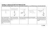
Figure 1. “T-Bar” Clip Installation
NOTE:
If you are going to install a
heater/blower kit, it should be done
before installing the back box. Refer
to Section 3.2.3, HEATER/BLOWER
KIT FIELD INSTALLATION.
NOTE:
When installing into a 2' x 4'
(.61 m x 1.22 m) ceiling grid, cut the
ceiling tile in half and install an addi-
tional “T” rail for support.

10 Pelco Manual C454M-C (1/98)
3.1.2 Hard Ceiling Mounting
For installing the back box in a hard ceiling, an optional backup plate is provided for
applications where additional reinforcement to the ceiling structure is needed.
To mount the back box directly into a hard ceiling, perform the following steps.
1. Determine the location of the back box. Ideally the back box cutout should be
adjacent to any ceiling structure.
2. Cut the opening in the ceiling (16-13/16" in diameter).
3. Insert the back box into the opening. Mark spots to drill holes through the side
of the back box at the locations where fasteners need to be located. Remove
the back box and drill the holes.
4. Using the appropriate fasteners (not supplied) attach the back box to any
adjacent structure through the drilled holes in the box.
Proceed to Section 3.2, WIRING INSTRUCTIONS.
3.1.2.1 Optional Backup Plate Installation
A backup plate assembly is supplied with all back boxes to be installed in hard
ceilings, and is for use in applications where additional reinforcement to the ceiling
structure is needed. To install the backup plate, do steps 1 through 2 in Section
3.1.2 and then proceed as follows. Refer to Figure 2.
1. Insert the back box into the opening in the ceiling and mark the ceiling with the
locations of four of the screw holes in the flange. The holes must be 90° apart.
2. Remove the back box and drill 13/64" screw holes in the ceiling at the marked
points.
3. Insert the two (2) pieces of the backup plate through the large hole and posi-
tion them around the opening. Connect the two halves using the studs pro-
vided.
4. Align the nuts in the plate with the four (4) screw holes in the ceiling.
5. Insert the back box into the ceiling, and align the screw holes in the ceiling
with the holes in the flange of the back box.
6. Attach the back box to the backup plate with four (4) 6-32 screws provided.
7. Use appropriate fasteners (not supplied) to attach the back box to any adja-
cent structure through the holes drilled in the side of the back box.
Proceed to Section 3.2, WIRING INSTRUCTIONS.

Pelco Manual C454M-C (1/98) 11
3.1.3 Pendant Mounting
The pendant back box is designed to be suspended from a suitable length of 1-1/2”
pipe threaded at both ends. This pipe can be interfaced to the IWM Series or IDM4018
wall mounts or to the MRWA wall adapter mount or MRCA ceiling adapter mount.
To install the pendant type back box, perform the following steps:
1. Select and install the mount of choice according to the instructions provided
with the mount. This may be a good time to route any needed wiring through
the mount. Refer to Section 3.2, WIRING INSTRUCTIONS.
2. Select the appropriate length of pipe (2-1/2" minimum length) and thread into
the mount. Tighten to approximately 30 ft/lb and tighten any locking means
that may be provided on the mount.
3. Slide the back box “cap” up the pipe.
On outdoor units first slide one (1) of the two (2) O-rings up the pipe, followed
by the “cap” and the second O-ring.
On indoor models while holding the “cap” in place, bring the back box into
place and engage the threaded flange on the back box with the pipe. (Be sure
to back out the locking screw in the flange prior to this.)
4. Spin the back box onto the pipe. The latches inside the back box may be used
as handles to provide a light torque to the box (approximately 20 ft/lb). Tighten
the lock screw.
5. Lower the “cap” onto the top of the back box. On outdoor models also lower
the external O-ring until it contacts the “cap”.
Proceed to Section 3.2, WIRING INSTRUCTIONS.
NOTE:
The length of pipe used may
effect noticeable motion on the video
display. If this occurs additional sup-
port of the pipe by bracing, guy wir-
ing, etc. will be required.
NOTE:
For outdoor models apply
pipe thread sealant to the pipe threads
prior to assembly.
Figure 2. Backup Plate Installation

12 Pelco Manual C454M-C (1/98)
3.2 WIRING INSTRUCTIONS
How your back box will be wired depends on the type of unit you have:
Units with an on-board receiver/driver
Units without an on-board receiver/driver (hard-wire applications)
Hardwire refers to installations using a remote receiver/driver or a true hardwire
controller.
Proceed to either Section 3.2.1, On-Board Receiver/Driver, or Section 3.2.2,
Hardwire or Remote Receiver/Driver.
3.2.1 On-Board Receiver/Driver
On models for suspended ceilings or hard ceilings, a plate is provided on the top of
the back box with 1/2" and 3/4" conduit knockouts.
1. Bring the wiring to the back box.
Video - Refer to Table A for the type of video coaxial cable to use.
Power - If the input power to the dome is 24 VAC, refer to Table B to determine
the size of wire to use. For outdoor units, make sure the wiring can supply
power for the heaters and fan as well as the receiver/driver. Refer to Section
5.0, SPECIFICATIONS, for power requirements.
Control - If you are using a Coaxitron
®
controller, the control signals to operate
the dome drive will be transmitted over the video coax.
If you are not using a Coaxitron
®
controller, bring wires to the back box for two
(2) RS-485 control lines (RX+ and RX-).
Refer to Figure 3, 4, or 5 for the following steps.
2. Install the coaxial cable to the BNC connector.
3. Install power to the 10-position terminal block. Make sure the power switch on
the side of the back box is off.
4. If you are not using Coaxitron
®
control, connect the control wiring to RXD+
and RXD-.
From controller To 4-wire terminal inside back box
TXD+ RXD+
TXD- RXD-
Proceed to Section 3.3, DOME DRIVE INSTALLATION.

Pelco Manual C454M-C (1/98) 13
Table A. Video Coaxial Cable Requirements
Cable Type* Maximum Distance
RG59/U 750 ft (229 m)
RG6/U 1,000 ft (305 m)
RG11/U 1,500 ft (457 m)
* Minimum cable requirements:
75 ohms
All-copper center conductor
All-copper braided shield with 95% braid coverage
Wire Gauge
Maximum distance from transformer to load
Table B. 24 VAC Wiring Distances
The following are the recommended maximum distances for 24 VAC applications
and are calculated with a 10-percent voltage drop. (10-percent is generally the
maximum allowable voltage drop for AC-powered devices.)
20 18 16 14 12 10
10 283 451 716 1142 1811 2880
(86) (137) (218) (348) (551) (877)
20 141 225 358 571 905 1440
(42) (68) (109) (174) (275) (438)
30 94 150 238 380 603 960
(28) (45) (72) (115) (183) (292)
40 70 112 179 285 452 720
(21) (34) (54) (86) (137) (219)
50 56 90 143 228 362 576
(17) (27) (43) (69) (110) (175)
60 47 75 119 190 301 480
(14) (22) (36) (57) (91) (146)
70 40 64 102 163 258 411
(12) (19) (31) (49) (78) (125)
80 35 56 89 142 226 360
(10) (17) (27) (43) (68) (109)
90 31 50 79 126 201 320
(9) (15) (24) (38) (61) (97)
100 28 45 71 114 181 288
(8) (13) (21) (34) (55) (87)
110 25 41 65 103 164 261
(7) (12) (19) (31) (49) (79)
120 23 37 59 95 150 240
(7) (11) (17) (28) (45) (73)
130 21 34 55 87 139 221
(6) (10) (16) (26) (42) (67)
140 20 32 51 81 129 205
(6) (9) (15) (24) (39) (62)
150 18 30 47 76 120 192
(5) (9) (14) (23) (36) (58)
160 17 28 44 71 113 180
(5) (8) (13) (21) (34) (54)
170 16 26 42 67 106 169
(4) (7) (12) (20) (32) (51)
180 15 25 39 63 100 160
(4) (7) (11) (19) (30) (48)
190 14 23 37 60 95 151
(4) (7) (11) (18) (28) (46)
200 14 22 35 57 90 144
(4) (6) (10) (17) (27) (43)
Total vA consumed
EXAMPLE:
An enclosure that re-
quires 80 vA and is installed 35 feet
(10 m) from the transformer would
require a minimum wire gauge of 20
Awg.
NOTE:
Distances are calculated in
feet; values in parentheses are
meters.

14 Pelco Manual C454M-C (1/98)
Figure 3. 24 VAC Back Box Wiring Diagram (for Dome Drives with Integral Receiver/Driver)

Pelco Manual C454M-C (1/98) 15
Figure 4. 120 VAC Back Box Wiring Diagram (for Dome Drives with Integral Receiver/Driver)

16 Pelco Manual C454M-C (1/98)
Figure 5. 230 VAC Back Box Wiring Diagram (for Dome Drives with Integral Receiver/Driver)

Pelco Manual C454M-C (1/98) 17
3.2.2 Hard-Wire or Remote Receiver/Driver
Refer to Figures 6 and 7 for wiring diagrams.
Refer to Table A for the type of video coaxial cable to use.
On models for suspended ceilings or hard ceilings, a plate is provided on the top of
the back box with 1/2" and 3/4" conduit knockouts.
If your back box has a power switch, make sure it is off before wiring power to the
back box.
A minimum of eleven (11) conductors plus coax are required for pan/tilt, motorized
zoom lens and camera power. Dome drives with presets (PP) require an additional
six (6) conductors for Type D or seven (7) conductors for Type E. The above does
not include the conductor requirements for heaters/blower which will need an addi-
tional two (2) plus ground.
The following cable distances are approximate and does not account for heaters/
blower.
Calculations are based on a 10% cable loss with both motors running.
Dome Drive Model Type
Non-Preset Models
Type B & C 11 Conductors 12 Conductors*
Preset Non-SL Models
Type D 17 Conductors 18 Conductors*
Preset SL Models
Type E 18 Conductors 19 Conductors*
20 Awg 153 ft (46.6 m) 281 ft (85.6 m)
18 Awg 244 ft (74.3 m) 447 ft (136.2 m)
16 Awg 387 ft (117.9 m) 710 ft (216.4 m)
* Using 2-conductor common.
A relay box (RB24) for use with a hardwire control only is available to extend the
operating distance (control to relay box) up to 15,000 ft over 18 Awg wire.
The following cable sizes are the minimum recommended for use with the heaters/
blower kit at the wattage and voltage listed.
122 watts @ 24 VAC
20 Awg 23 ft (7 m)
18 Awg 37 ft (11.2 m)
16 Awg 58 ft (17.6 m)
127 watts @ 120 VAC
20 Awg 558 ft (170 m)
18 Awg 888 ft (270.6 m)
16 Awg 1,410 ft (429.7 m)
129 watts @ 230 VAC
20 Awg 2,020 ft (615.7 m)
18 Awg 3,213 ft (979.3 m)
16 Awg 5,100 ft (1,554.4 m)
Proceed to Section 3.3, DOME DRIVE INSTALLATION.

18 Pelco Manual C454M-C (1/98)
Figure 6. Wiring Diagram, Hard-Wire Control with Heater
NOTE:
For fixed mount or dome drive with blower/heaters and without integral receiver/driver.

Pelco Manual C454M-C (1/98) 19
Figure 7. Wiring Diagram, Hard-Wire Control without Heater
NOTE:
For use in domes without integral receiver/driver or heaters and blower.

20 Pelco Manual C454M-C (1/98)
3.2.3 Heater/Blower Kit Field Installation
The kits are shipped partially assembled, to complete assembly and to install the
heater/blower kit perform the following steps:
1. Place the fan over the four (4) unused internally threaded standoffs located on
the back plate (refer to Figure 11). Note the arrow indicating the air flow direc-
tion of the fan, installing with arrow pointing “away” from back plate.
2. Place the heater assembly over the fan aligning the four (4) holes in the plate
with the holes in the fan and the standoffs.
3. Install the four (4) #6 lock washers and screws through the plate and the fan
threading the screws into the standoffs.
4. Mounting through one hole of the thermostat mounting tab, attach the thermo-
stat to the standoff of the terminal block on the end nearest the fan using the 6-
32 x 3/8" screw (see Figure 11).
5. Connect the terminated wires to the terminal block as shown in Figures 3
through 6 depending on back box configuration.
3.3 DOME DRIVE INSTALLATION
Back box installation is now complete. Proceed with the installation of the dome
drive or fixed mount unit. Refer to the manual provided with the dome drive or fixed
mount for further installation instructions.
/