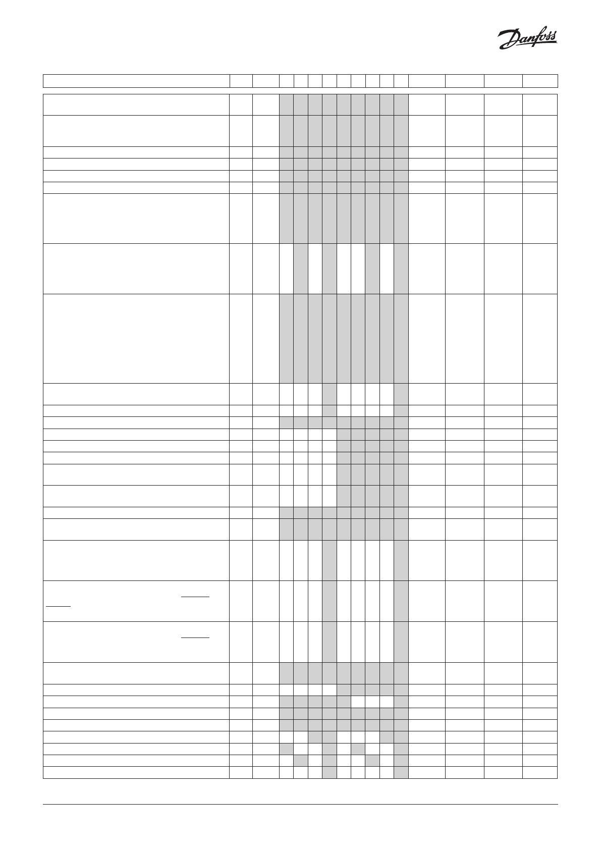
Compact - continued R-W Code 1 2 3 4 5 6 7 8 9 Min. Max. Fac. Actual
Replace the controller's factory settings with the
present settings
3-3* o67 1 1 1 1 1 1 1 1 1 0/Off 1/On 0/Off
Rail heat control
0=not used, 1=pulse control with timer function (o41
and o42), 2=pulse control with dew point functionA
1-2 o85 1 1 1 1 1 1 1 1 1 0 2 0
Dew point value where the rail heat is minimum
1-2 o86 1 1 1 1 1 1 1 1 1 -10°C "o87" 8
Dew point value where the rail heat is 100% on
1-2 o87 1 1 1 1 1 1 1 1 1 "o86" 50°C 17
Lowest permitted rail heat effect in %
1-2 o88 1 1 1 1 1 1 1 1 1 0 % 100 % 30
Time delay from "open door” refrigeration is started
1-2 o89 1 1 1 1 1 1 1 1 1 0 min. 240 min. 30
Fan operation at stopped cooling (forced closing):
0= Stopped (defrost allowed)
1= Running (defrost allowed)
2= Stopped (defrost not allowed)
3= Running (defrost not allowed)
1-2 o90 1 1 1 1 1 1 1 1 1 0 3 1
Light and night blinds defined
0: Light is switched off and night blind is opened
when the main switch is off
1: Light and night blinds are independent of main
switch
1-2 o98 1 1 1 1 0 1 0
Configuration of alarm relay
The alarm relay will be activated by an alarm in one or
more of the following priorities.
Setting:
0 = The relay is not activated by alarms
1 = Only high priority alarms
2 = High priority and intermediate priority alarms
3 = High priority, intermediate priority and low
priority
1-2 P41 1 1 1 1 1 1 1 1 1 0 3 2
Max. opening time of night blinds after a manual
override with DI activation.
1-2 P60 1 1 0 min. 60 min. 5
Stop time for fans while the night blinds roll down 1-2 P65 1 1 0 sec 300 sec 0
Cycle time for rail heat at PWM on AO1 1-2 P82 1 1 1 1 1 1 1 1 1 4 sec 60 sec 10
User defined refrigerant 3-digit Rfg. factor K1 1-3* P83 1 1 1 1 1 -999 999 300
User defined refrigerant 3-digit Rfg. factor K2 1-3* P84 1 1 1 1 1 -999 999 300
User defined refrigerant 3-digit Rfg. factor K3 1-3* P85 1 1 1 1 1 -999 999 300
Max. limitation of the superheat reference when
regulated with liquid-filled evaporator
1-2 P86 1 1 1 1 1 "P87" 20°C 3
Min. limitation of the superheat reference when
regulated with liquid-filled evaporator
1-2 P87 1 1 1 1 1 0°C "P86" 1
Access code 1 (simple access) 1-1 P88 1 1 1 1 1 1 1 1 1 0 999 0
Locking the display control. 0/Off=operation. 1/
On=locked
1-2 P89 1 1 1 1 1 1 1 1 1 0/Off 1/On 0/Off
Configuration of relay output DO2: 0=not used,
1=fan, 2=fan Eco, 3=defrost, 4=rail heat, 5=alarm,
6=light, 7=night blinds, 8=compressor, 9=compressor
2, 10=heating element
1-3* q02 1 1 0 10 0
Configuration of relay output DO3: 0=not used,
1=fan, 2=fan Eco, 3=defrost, 4=rail heat, 5=alarm,
6=light, 7=night blinds, 8=compressor, 9=compressor
2, 10=heating element
1-3* q03 1 1 0 10 0
Configuration of relay output DO4: 0=not used,
1=fan, 2=fan Eco, 3=defrost, 4=rail heat, 5=alarm,
6=light, 7=night blinds, 8=compressor, 9=compressor
2, 10=heating element
1-3* q04 1 1 0 10 0
Configuration of analogue output AO1: 0=not used.
1=rail heat PWM
1-3* q09 1 1 1 1 1 1 1 1 1 0 1 0
Manual control of output: AKV valve 0-100% 1-2** q11 1 1 1 1 1 0 % 100 % 0
Manual control of output: Compressor1/LLSV 1-2** q12 1 1 1 1 1 1 0/Off 1/On 0/Off
Manual control of output: Fan 1-2** q13 1 1 1 1 1 1 1 1 1 0/Off 1/On 0/Off
Manual control of output: Defrost 1-2** q14 1 1 1 1 1 1 1 1 1 0/Off 1/On 0/Off
Manual control of output: Rail heat 1-2** q15 1 1 1 1 0/Off 1/On 0/Off
Manual control of output: Alarm 1-2** q16 1 1 1 1 0/Off 1/On 0/Off
Manual control of output: Light 1-2** q17 1 1 1 1 0/Off 1/On 0/Off
Manual control of output: Compressor 2 1-2** q19 1 1 0/Off 1/On 0/Off
© Danfoss | DCS (vt) | 2019.08
AN300028324304en-000301 | 13


