Page is loading ...

CASH VALVE TYPES FR, FR-6 AND FR-10
WATER/AIR/OIL/GAS BACK PRESSURE VALVE INSTALLATION INSTRUCTIONS
Before installation, these instructions must be carefully read and understood.
Emerson.com/FinalControl © 2018 Emerson. All rights reserved. VCIOM-10798-EN 19/06
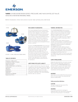
DESCRIPTION
The Types FR, FR-6 and FR-10 are fully
automatic back pressure valves designed
to dependably maintain a desired pressure
in a vessel or system by maintaining a
predetermined valve inlet pressure and
relieving excess pressure into a lower pressure
line. FR Series valves are not emergency
relief devices, but are designed for continuous
pressure regulation.
SPECIFICATION DATA
Service: Air, water, oils and gases (except
steam)
Sizes: 1 ¼", 1 ½" and 2"
End Connections: Threaded internal inlet and
outlet
Available Body Material:
FR: Bronze, Iron, Steel or SST
FR-6: Bronze or SST
FR-10: Iron
Maximum Temperature:
FR and FR-6: 600°F (315.6°C)
FR-10: 450°F (232.2°C)
Maximum Pressure:
FR: 400 psi (27.6 bar)
FR-6: 600 psi (41.4 bar)
FR-10: 250 psi (17.2 bar)
Capacity:
For specific capacity information, consult the
factory.
CONSTRUCTION
See component description for materials of
construction.
GENERAL INSTALLATION INSTRUCTIONS
Connect the supply line (usually the pump
discharge line) to either the right or left hand
body connection. The remaining right or left
hand connection should be connected to the
service line or plugged depending on the type
of installation. The bottom connection, which is
indicated by an arrow on the valve body, should
be connected to the return or by-pass line.
Before installing the valve, the piping and valve
should be thoroughly flushed out to remove any
foreign material.
Types FR, FR-6 and FR-10 valves are typically
installed in the horizontal position with the
spring chamber upright. Consult the factory or
its authorized representative before installing
the valve in other positions.
OPERATING INSTRUCTIONS
Adjusting the Delivery Pressure:
The regulator’s delivery pressure setting is
adjusted by turning the adjusting screw (2) or
optional T-handle (1) at the top of the spring
chamber (5) after loosening the adjusting
screw lock nut (3). To increase the delivery
pressure, turn the adjusting screw clockwise
(into the spring chamber). To decrease the
delivery pressure, turn the adjusting screw
counter-clockwise (out of the spring chamber).
Tighten the adjusting screw lock nut after the
adjustment has been made. Draw flow through
the valve and shutoff, after adjustment, to
check for proper set pressure.
MAINTENANCE INSTRUCTIONS
CAUTION
Before attempting to replace any spare parts
be sure to shut off all pressure connections to
the valve. With the valve closed however, system
pressure could still be locked between the shut
off valve and the inlet and/or outlet sides of the
regulator. Before proceeding with any valve
service be certain to relieve the pressure from
both sides of the regulator.
Refer to section view for parts identification.
Repair parts can easily be installed without
removing the regulator from the line.

2
CASH VALVE TYPES FR, FR-6 AND FR-10
WATER/AIR/OIL/GAS BACK PRESSURE VALVE INSTALLATION INSTRUCTIONS
Neither Emerson, Emerson Automation Solutions, nor any of their affiliated entities assumes responsibility for the selection, use or maintenance of any product.
Responsibility for proper selection, use, and maintenance of any product remains solely with the purchaser and end user.
Cash Valve is a mark owned by one of the companies in the Emerson Automation Solutions business unit of Emerson Electric Co. Emerson Automation Solutions,
Emerson andthe Emerson logo are trademarks and service marks of Emerson Electric Co. All other marks are the property of their respective owners.
The contents of this publication are presented for informational purposes only, and while every effort has been made to ensure their accuracy, they are not to be
construed as warranties or guarantees, express or implied, regarding the products or services described herein or their use or applicability. All sales are governed by
our terms and conditions, which are available upon request. We reserve the right to modify or improve the designs or specifications of such products at any time without
notice.
Emerson.com/FinalControl
No. Component Description Construction
1 Adjusting Screw Cap
(FR, FR6 only)
Brass
2 Adjusting Screw Steel
3 Lock Nut Brass or Steel
4 Gasket Polypropylene
5 Spring Chamber Iron (FR, FR6,
FR10)
Bronze, Steel
or SST (FR, FR6
only)
6 Spring Button Brass
7 Pressure Spring Steel
8 Name Plate Aluminum
9 Drive Screw SST
10 Nut Steel
11 Washer SST
12 Pressure Plate Brass
13 Screw Steel
14 Diaphragm Buna-N, Monel,
Viton (FR, FR6,
FR10)
Bronze or SST
(FR, FR6 only)
15 Gasket Aramid Fiber or
Teflon
16 Diaphragm Ring (FR6
only)
Brass
17 O-ring Buna-N or Teflon
18 Ball Seat SST
19 Seat Ring SST
20 Body Seat Brass or SST
21 Body Iron (FR, FR6,
FR10)
Bronze, Steel
or SST (FR, FR6
only)
FIGURE 1
/