Page is loading ...

MAKING MODERN LIVING POSSIBLE
Design Guide
VLT
®
AutomationDrive

Contents
1 How to Read this Design Guide
7
1.1.1 Symbols 7
1.1.2 Abbreviations 7
1.1.3 Definitions 8
2 Safety and Conformity
11
2.1 Safety Precautions
11
3 Introduction to FC 300
15
3.1 Product Overview
15
3.2.1 Control Principle 17
3.2.2 FC 300 Controls 17
3.2.3 FC 301 vs. FC 302 Control Principle 18
3.2.4 Control Structure in VVC
plus
Advanced Vector Control 19
3.2.5 Control Structure in Flux Sensorless (FC 302 only) 20
3.2.6 Control Structure in Flux with Motor Feedback 21
3.2.7 Internal Current Control in VVC
plus
Mode 22
3.2.8 Local (Hand On) and Remote (Auto On) Control 22
3.3 Reference Handling
23
3.3.1 Reference Limits 24
3.3.2 Scaling of Preset References and Bus References 25
3.3.3 Scaling of Analog and Pulse References and Feedback 25
3.3.4 Dead Band Around Zero 26
3.4 PID Control
30
3.4.1 Speed PID Control 30
3.4.2 Tuning PID Speed Control 31
3.4.3 Process PID Control 32
3.4.4 Example of Process PID Control 34
3.4.5 Ziegler Nichols Tuning Method 35
3.5 General Aspects of EMC
37
3.5.1 General Aspects of EMC Emissions 37
3.5.2 EMC Test Results 38
3.5.3 Emission Requirements 39
3.5.4 Immunity Requirements 40
3.6.1 PELV - Protective Extra Low Voltage 41
3.8 Brake Functions in FC 300
42
3.8.1 Mechanical Holding Brake 42
3.8.2 Dynamic Braking 43
3.8.3 Selection of Brake Resistor 43
Contents FC 300 Design Guide
MG.33.BD.02 - VLT
®
is a registered Danfoss trademark 1

3.9.1 Mechanical Brake Control 45
3.9.2 Hoist Mechanical Brake 46
3.9.3 Brake Resistor Cabling 47
3.10 Smart Logic Controller
47
3.11 Extreme Running Conditions
49
3.11.1 Motor Thermal Protection 49
3.12 Safe Stop of FC 300
51
3.12.2 Installation of External Safety Device in Combination with MCB 112 56
3.12.3 Safe Stop Commissioning Test 57
3.13 Certificates
58
4 FC 300 Selection
60
4.1 Electrical Data - 200-240V
60
4.2 Electrical Data - 380-500V
63
4.3 Electrical Data - 525-600V
71
4.4 Electrical Data - 525-690V
74
4.5 General Specifications
85
4.7.1 Acoustic Noise 90
4.8.1 du/dt Conditions 91
4.9 Special Conditions
94
4.9.1 Manual Derating 94
4.6.1.1 Derating for Running at Low Speed 94
4.9.2 Automatic Derating 94
5 How to Order
95
5.1.1 Ordering from Type Code 95
5.1.2 Drive Configurator 95
5.2.1 Ordering Numbers: Options and Accessories 99
5.2.2 Ordering Numbers: Spare Parts 100
5.2.3 Ordering Numbers: Accessory Bags 100
5.2.4 Ordering Numbers: High Power Kits 101
5.2.5 Ordering Numbers: Brake Resistors 10% 101
5.2.6 Ordering Numbers: Brake Resistors 40% 106
5.2.7 Flat Packs 111
5.2.8 Ordering Numbers: Harmonic Filters 113
5.2.9 Ordering Numbers: Sine Wave Filter Modules, 200-500 VAC 115
5.2.10 Ordering Numbers: Sine-Wave Filter Modules, 525-690 VAC 116
5.2.11 Ordering Numbers: du/dt Filters, 380-480/500V AC 116
5.2.12 Ordering Numbers: du/dt Filters, 525-690V AC 116
6 Mechanical Installation - Frame Size A, B and C
117
Contents FC 300 Design Guide
2 MG.33.BD.02 - VLT
®
is a registered Danfoss trademark

6.1.1 Safety Requirements of Mechanical Installation 117
6.1.2 Mechanical Mounting 120
7 Mechanical Installation - Frame size D, E and F
121
7.1 Pre-installation
121
7.1.1 Planning the Installation Site 121
7.1.2 Receiving the Frequency Converter 121
7.1.3 Transportation and Unpacking 121
7.1.4 Lifting 121
7.1.5 Mechanical Dimensions 123
7.1.6 Mechanical Dimensions, 12-Pulse Units 130
7.2 Mechanical Installation
133
7.2.1 Tools Needed 133
7.2.2 General Considerations 133
7.2.3 Terminal Locations - Frame size D 135
7.2.4 Terminal Locations - Frame size E 137
7.2.5 Terminal Locations - Frame size F 142
7.2.6 Terminal Locations, F8-F13 - 12-Pulse 146
7.2.7 Cooling and Airflow 151
7.2.8 Installation on the Wall - IP21 (NEMA 1) and IP54 (NEMA 12) Units 152
7.2.9 Gland/Conduit Entry - IP21 (NEMA 1) and IP54 (NEMA12) 153
7.2.10 Gland/Conduit Entry, 12-Pulse - IP21 (NEMA 1) and IP54 (NEMA12) 154
7.2.11 IP21 Drip Shield Installation (Frame size D1 and D2 ) 156
8 Electrical Installation
157
8.1 Connections- Frame Sizes A, B and C
157
8.1.1 Removal of Knockouts for Extra Cables 158
8.1.2 Connection to Mains and Earthing 158
8.1.3 Motor Connection 160
8.1.4 Relay Connection 168
8.2 Connections - Frame Sizes D, E and F
169
8.2.1 Torque 169
8.2.2 Power Connections 169
8.2.3 Power Connections 12-Pulse Drives 180
8.2.4 Shielding against Electrical Noise 189
8.2.5 External Fan Supply 189
8.3 Fuses and Circuit Breakers
190
8.3.1 Recommendations 190
8.3.2 CE Compliance 191
8.4 Disconnectors and Contactors
203
8.4.1 Mains Disconnectors 203
Contents FC 300 Design Guide
MG.33.BD.02 - VLT
®
is a registered Danfoss trademark 3

8.4.4 F-Frame Mains Contactors 205
8.5 Additional Motor Information
206
8.5.1 Motor Cable 206
8.5.2 Motor Thermal Protection 206
8.5.3 Parallel Connection of Motors 206
8.5.5 Motor Bearing Currents 208
8.6 Control Cables and Terminals
209
8.6.1 Access to Control Terminals 209
8.6.2 Control Cable Routing 209
8.6.3 Control Terminals 210
8.6.4 Switches S201, S202, and S801 211
8.6.5 Electrical Installation, Control Terminals 211
8.6.6 Basic Wiring Example 212
8.6.7 Electrical Installation, Control Cables 213
8.6.8 12-Pulse Control Cables 215
8.6.9 Relay Output 218
8.6.10 Brake Resistor Temperature Switch 218
8.7 Additional Connections
218
8.7.1 DC Bus Connection 218
8.7.2 Load Sharing 218
8.7.3 Installation of Brake Cable 219
8.7.4 How to Connect a PC to the Frequency Converter 219
8.7.5 The FC 300 PC Software 219
8.8.1 High Voltage Test 220
8.8.2 Earthing 220
8.8.3 Safety Earth Connection 220
8.9 EMC-correct Installation
220
8.9.1 Electrical Installation - EMC Precautions 220
8.9.2 Use of EMC-Correct Cables 222
8.9.3 Earthing of Screened Control Cables 224
8.9.4 RFI Switch 224
8.10.1 Mains Supply Interference/Harmonics 225
8.10.2 The Effect of Harmonics in a Power Distribution System 225
8.10.3 Harmonic Limitation Standards and Requirements 226
8.10.4 Harmonic Mitigation 226
8.10.5 Harmonic Calculation 226
8.11 Residual Current Device - FC 300 DG
226
8.12 Final Setup and Test
227
9 Application Examples
228
9.1.1 Encoder Connection 233
Contents FC 300 Design Guide
4 MG.33.BD.02 - VLT
®
is a registered Danfoss trademark

9.1.2 Encoder Direction 233
9.1.3 Closed Loop Drive System 233
9.1.4 Programming of Torque Limit and Stop 233
10 Options and Accessories
235
10.1.1 Mounting of Option Modules in
Slot A 235
10.1.2 Mounting of Option Modules in
Slot B 235
10.1.3 Mounting of Options in Slot C 236
10.2 General Purpose Input Output Module MCB 101
236
10.2.1 Galvanic Isolation in the MCB 101 236
10.2.2 Digital Inputs - Terminal X30/1-4: 238
10.2.3 Analog Inputs - Terminal X30/11, 12: 238
10.2.4 Digital Outputs - Terminal X30/6, 7: 238
10.2.5 Analog Output - Terminal X30/8: 238
10.3 Encoder Option MCB 102
239
10.4 Resolver Option MCB 103
240
10.5 Relay Option MCB 105
241
10.6 24V Back-Up Option MCB 107
243
10.7 MCB 112 PTC Thermistor Card
244
10.8 MCB 113 Extended Relay Card
246
10.9 Brake Resistors
247
10.10 LCP Panel Mounting Kit
247
10.11 IP21/IP 4X/ TYPE 1 Enclosure Kit
248
10.12 Mounting Bracket for Frame Size A5, B1, B2, C1 and C2
251
10.13 Sine-wave Filters
253
10.14 High Power Options
253
10.14.1 Frame Size F Options 253
11 RS-485 Installation and Set-up
255
11.1 Overview
255
11.2 Network Connection
255
11.3 Bus Termination
255
11.4.1 EMC Precautions 256
11.5 Network Configuration
256
11.5.1 FC 300 Frequency Converter Set-up 256
11.6 FC Protocol Message Framing Structure - FC 300
257
11.6.1 Content of a Character (byte) 257
11.6.2 Telegram Structure 257
11.6.3 Length (LGE) 257
11.6.4 Frequency Converter Address (ADR) 257
Contents FC 300 Design Guide
MG.33.BD.02 - VLT
®
is a registered Danfoss trademark 5

11.6.5 Data Control Byte (BCC) 257
11.6.6 The Data Field 257
11.6.7 The PKE Field 258
11.6.8 Parameter Number (PNU) 259
11.6.9 Index (IND) 259
11.6.10 Parameter Value (PWE) 259
11.6.11 Data Types Supported by FC 300 260
11.6.12 Conversion 260
11.6.13 Process Words (PCD) 261
11.7 Examples
261
11.7.1 Writing a Parameter Value 261
11.7.2 Reading a Parameter Value 261
11.8 Modbus RTU Overview
261
11.8.1 Assumptions 261
11.8.2 What the User Should Already Know 261
11.8.3 Modbus RTU Overview 261
11.8.4 Frequency Converter with Modbus RTU 262
11.9.1 Frequency Converter with Modbus RTU 262
11.10 Modbus RTU Message Framing Structure
262
11.10.1 Frequency Converter with Modbus RTU 262
11.10.2 Modbus RTU Message Structure 262
11.10.3 Start/Stop Field 263
11.10.4 Address Field 263
11.10.5 Function Field 263
11.10.6 Data Field 263
11.10.7 CRC Check Field 263
11.10.8 Coil Register Addressing 264
11.10.9 How to Control the Frequency Converter 266
11.10.10 Function Codes Supported by Modbus RTU 266
11.10.11 Modbus Exception Codes 266
11.11 How to Access Parameters
266
11.11.1 Parameter Handling 266
11.11.2 Storage of Data 266
11.11.3 IND 266
11.11.4 Text Blocks 266
11.11.5 Conversion Factor 267
11.11.6 Parameter Values 267
11.12 Danfoss FC Control Profile
267
Index
275
Contents FC 300 Design Guide
6 MG.33.BD.02 - VLT
®
is a registered Danfoss trademark

1 How to Read this Design Guide
This Design Guide will introduce all aspects of your FC 300.
Available literature for FC 300
- The VLT AutomationDrive Operating Instructions
MG.33.AX.YY provide the neccessary information
for getting the drive up and running.
- The VLT AutomationDrive High Power Operating
Instructions MG.33.UX.YY
- The VLT AutomationDrive Design Guide MG.
33.BX.YY entails all technical information about
the drive and customer design and applications.
- The VLT AutomationDrive Programming Guide
MG.33.MX.YY provides information on how to
programme and includes complete parameter
descriptions.
- The VLT AutomationDrive Profibus Operating
Instructions MG.33.CX.YY provide the information
required for controlling, monitoring and
programming the drive via a Profibus fieldbus.
- The VLT AutomationDrive DeviceNet Operating
Instructions MG.33.DX.YY provide the information
required for controlling, monitoring and
programming the drive via a DeviceNet fieldbus.
X = Revision number
YY = Language code
Danfoss Drives technical literature is also available online
at www.danfoss.com/BusinessAreas/DrivesSolutions/
Documentations/Technical+Documentation.
1.1.1
Symbols
Symbols used in this guide.
NOTE
Indicates something to be noted by the reader.
CAUTION
Indicates a potentially hazardous situation which, if not
avoided, may result in minor or moderate injury or
equipment damage.
WARNING
Indicates a potentially hazardous situation which, if not
avoided, could result in death or serious injury.
*
Indicates default setting
1.1.2 Abbreviations
Alternating current AC
American wire gauge AWG
Ampere/AMP A
Automatic Motor Adaptation AMA
Current limit I
LIM
Degrees Celsius
°C
Direct current DC
Drive Dependent D-TYPE
Electro Magnetic Compatibility EMC
Electronic Thermal Relay ETR
frequency converter FC
Gram g
Hertz Hz
Horsepower hp
Kilohertz kHz
Local Control Panel LCP
Meter m
Millihenry Inductance mH
Milliampere mA
Millisecond ms
Minute min
Motion Control Tool MCT
Nanofarad nF
Newton Meters Nm
Nominal motor current I
M,N
Nominal motor frequency f
M,N
Nominal motor power P
M,N
Nominal motor voltage U
M,N
Parameter par.
Protective Extra Low Voltage PELV
Printed Circuit Board PCB
Rated Inverter Output Current I
INV
Revolutions Per Minute RPM
Regenerative terminals Regen
Second sec.
Synchronous Motor Speed n
s
Torque limit T
LIM
Volts V
The maximum output current I
VLT,MAX
The rated output current supplied by the
frequency converter
I
VLT,N
How to Read this Design Gui... FC 300 Design Guide
MG.33.BD.02 - VLT
®
is a registered Danfoss trademark 7
1 1

1.1.3 Definitions
Frequency converter:
Coast
The motor shaft is in free mode. No torque on motor.
I
MAX
The maximum output current.
I
N
The rated output current supplied by the frequency
converter.
U
MAX
The maximum output voltage.
Input:
Control command
Start and stop the connected motor by means of LCP and
the digital inputs.
Functions are divided into two groups.
Functions in group 1 have higher priority than functions in
group 2.
Group 1 Reset, Coasting stop, Reset and Coasting stop,
Quick-stop, DC braking, Stop and the "Off" key.
Group 2 Start, Pulse start, Reversing, Start reversing, Jog
and Freeze output
Motor:
f
JOG
The motor frequency when the jog function is activated
(via digital terminals).
f
M
Motor frequency. Output from the frequency converter.
Output frequency is related to the shaft speed on motor
depending on number of poles and slip frequency.
f
MAX
The maximum output frequency the frequency converter
applies on its output. The maximum output frequency is
set in limit par. 4-12, 4-13 and 4-19.
f
MIN
The minimum motor frequency from frequency converter.
Default 0 Hz.
f
M,N
The rated motor frequency (nameplate data).
I
M
The motor current.
I
M,N
The rated motor current (nameplate data).
n
M,N
The rated motor speed (nameplate data).
n
s
Synchronous motor speed
n
s
=
2 ×
par
. 1 − 23 × 60
s
par
. 1 − 39
P
M,N
The rated motor power (nameplate data).
T
M,N
The rated torque (motor).
U
M
The instantaneous motor voltage.
U
M,N
The rated motor voltage (nameplate data).
Break-away torque
175ZA078.10
Pull-out
rpm
Torque
η
The efficiency of the frequency converter is defined as the
ratio between the power output and the power input.
Start-disable command
A stop command belonging to the group 1 control
commands - see this group.
Stop command
See Control commands.
References:
Analog Reference
An analog signal applied to input 53 or 54. The signal can
be either Voltage 0-10V (FC 301 and FC 302) or -10 -+10V
(FC 302). Current signal 0-20 mA or 4-20 mA.
Binary Reference
A signal applied to the serial communication port (RS-485
term 68 – 69).
Preset Reference
A defined preset reference to be set from -100% to +100%
of the reference range. Selection of eight preset references
via the digital terminals.
How to Read this Design Gui... FC 300 Design Guide
8 MG.33.BD.02 - VLT
®
is a registered Danfoss trademark
11

Pulse Reference
A pulse reference applied to term 29 or 33, selected by
par. 5-13 or 5-15 [32]. Scaling in par. group 5-5*.
Ref
MAX
Determines the relationship between the reference input
at 100% full scale value (typically 10V, 20mA) and the
resulting reference. The maximum reference value set in
3-03 Maximum Reference.
Ref
MIN
Determines the relationship between the reference input
at 0% value (typically 0V, 0mA, 4mA) and the resulting
reference. The minimum reference value set in
3-02 Minimum Reference.
Miscellaneous:
Analog Inputs
The analog inputs are used for controlling various
functions of the frequency converter.
There are two types of analog inputs:
Current input, 0-20mA and 4-20mA
Voltage input, 0-10V DC (FC 301)
Voltage input, -10 - +10V DC (FC 302).
Analog Outputs
The analog outputs can supply a signal of 0-20mA,
4-20mA.
Automatic Motor Adaptation, AMA
AMA algorithm determines the electrical parameters for
the connected motor at standstill.
Brake Resistor
The brake resistor is a module capable of absorbing the
brake power generated in regenerative braking. This
regenerative braking power increases the intermediate
circuit voltage and a brake chopper ensures that the
power is transmitted to the brake resistor.
CT Characteristics
Constant torque characteristics used for all applications
such as conveyor belts, displacement pumps and cranes.
Digital Inputs
The digital inputs can be used for controlling various
functions of the frequency converter.
Digital Outputs
The frequency converter features two Solid State outputs
that can supply a 24V DC (max. 40mA) signal.
DSP
Digital Signal Processor.
ETR
Electronic Thermal Relay is a thermal load calculation
based on present load and time. Its purpose is to estimate
the motor temperature.
Hiperface
®
Hiperface
®
is a registered trademark by Stegmann.
Initialising
If initialising is carried out (14-22 Operation Mode), the
frequency converter returns to the default setting.
Intermittent Duty Cycle
An intermittent duty rating refers to a sequence of duty
cycles. Each cycle consists of an on-load and an off-load
period. The operation can be either periodic duty or non-
periodic duty.
LCP
The Local Control Panel makes up a complete interface for
control and programming of the frequency converter. The
control panel is detachable and can be installed up to 3
metres from the frequency converter, i.e. in a front panel
by means of the installation kit option.
NLCP
Numerical Local Control Panel interface for control and
programming of frequency converter. The display is
numerical and the panel is basically used for display
process values. The NLCP has no storing and copy
function.
lsb
Least significant bit.
msb
Most significant bit.
MCM
Short for Mille Circular Mil, an American measuring unit for
cable cross-section. 1 MCM = 0.5067 mm
2
.
On-line/Off-line Parameters
Changes to on-line parameters are activated immediately
after the data value is changed. Changes to off-line
parameters are not activated until you enter [OK] on the
LCP.
Process PID
The PID regulator maintains the desired speed, pressure,
temperature, etc. by adjusting the output frequency to
match the varying load.
PCD
Process Data
Pulse Input/Incremental Encoder
An external digital sensor used for feedback information of
motor speed and direction. Encoders are used for high
speed accuracy feedback and in high dynamic applications.
The encoder connection is either via term 32 and 32 or
encoder option MCB 102.
RCD
Residual Current Device.
Set-up
You can save parameter settings in four Set-ups. Change
between the four parameter Set-ups and edit one Set-up,
while another Set-up is active.
SFAVM
Switching pattern called Stator Flux oriented Asynchronous
Vector Modulation (14-00 Switching Pattern).
Slip Compensation
The frequency converter compensates for the motor slip
by giving the frequency a supplement that follows the
How to Read this Design Gui... FC 300 Design Guide
MG.33.BD.02 - VLT
®
is a registered Danfoss trademark 9
1 1

measured motor load keeping the motor speed almost
constant.
Smart Logic Control (SLC)
The SLC is a sequence of user defined actions executed
when the associated user defined events are evaluated as
true by the Smart Logic Controller. (Par. group 13-** Smart
Logic Control (SLC).
STW
Status Word
FC Standard Bus
Includes RS -485 bus with FC protocol or MC protocol. See
8-30 Protocol.
Thermistor:
A temperature-dependent resistor placed where the
temperature is to be monitored (frequency converter or
motor).
THD
Total Harmonic Distortion state the total contribution of
harmonic.
Trip
A state entered in fault situations, e.g. if the frequency
converter is subject to an over-temperature or when the
frequency converter is protecting the motor, process or
mechanism. Restart is prevented until the cause of the
fault has disappeared and the trip state is cancelled by
activating reset or, in some cases, by being programmed
to reset automatically. Trip may not be used for personal
safety.
Trip Locked
A state entered in fault situations when the frequency
converter is protecting itself and requiring physical
intervention, e.g. if the frequency converter is subject to a
short circuit on the output. A locked trip can only be
cancelled by cutting off mains, removing the cause of the
fault, and reconnecting the frequency converter. Restart is
prevented until the trip state is cancelled by activating
reset or, in some cases, by being programmed to reset
automatically. Trip may not be used for personal safety.
VT Characteristics
Variable torque characteristics used for pumps and fans.
VVC
plus
If compared with standard voltage/frequency ratio control,
Voltage Vector Control (VVC
plus
) improves the dynamics
and the stability, both when the speed reference is
changed and in relation to the load torque.
60° AVM
Switching pattern called 60°Asynchronous Vector
Modulation (14-00 Switching Pattern).
Power Factor
The power factor is the relation between I
1
and I
RMS
.
Power
factor
=
3
x
U
x
I
1
cos
ϕ
3
x
U
x
I
RMS
The power factor for 3-phase control:
=
I
1
x
cos
ϕ1
I
RMS
=
I
1
I
RMS
since
cos
ϕ1 = 1
The power factor indicates to which extent the frequency
converter imposes a load on the mains supply.
The lower the power factor, the higher the I
RMS
for the
same kW performance.
I
RMS
=
I
1
2
+
I
5
2
+
I
7
2
+ .. +
I
n
2
In addition, a high power factor indicates that the different
harmonic currents are low.
All Danfoss frequency converters have built-in DC coils in
the DC link to have a high power factor and to reduce the
THD on the main supply.
How to Read this Design Gui... FC 300 Design Guide
10 MG.33.BD.02 - VLT
®
is a registered Danfoss trademark
11

2 Safety and Conformity
2.1 Safety Precautions
WARNING
The voltage of the frequency converter is dangerous
whenever connected to mains. Incorrect installation of the
motor, frequency converter or fieldbus may cause death,
serious personal injury or damage to the equipment.
Consequently, the instructions in this manual, as well as
national and local rules and safety regulations, must be
complied with.
Safety Regulations
1. The mains supply to the frequency converter
must be disconnected whenever repair work is to
be carried out. Check that the mains supply has
been disconnected and that the necessary time
has elapsed before removing motor and mains
supply plugs.
2. The [OFF] button on the control panel of the
frequency converter does not disconnect the
mains supply and consequently it must not be
used as a safety switch.
3. The equipment must be properly earthed, the
user must be protected against supply voltage
and the motor must be protected against
overload in accordance with applicable national
and local regulations.
4. The earth leakage current exceeds 3.5mA.
5. Protection against motor overload is not included
in the factory setting. If this function is desired,
set 1-90 Motor Thermal Protection to data value
ETR trip 1 [4] or data value ETR warning 1 [3].
6. Do not remove the plugs for the motor and
mains supply while the frequency converter is
connected to mains. Check that the mains supply
has been disconnected and that the necessary
time has elapsed before removing motor and
mains plugs.
7. Please note that the frequency converter has
more voltage sources than L1, L2 and L3, when
load sharing (linking of DC intermediate circuit)
or external 24V DC are installed. Check that all
voltage sources have been disconnected and that
the necessary time has elapsed before
commencing repair work.
Warning against unintended start
1. The motor can be brought to a stop by means of
digital commands, bus commands, references or
a local stop, while the frequency converter is
connected to mains. If personal safety consider-
ations (e.g. risk of personal injury caused by
contact with moving machine parts following an
unintentional start) make it necessary to ensure
that no unintended start occurs, these stop
functions are not sufficient. In such cases the
mains supply must be disconnected or the Safe
Stop function must be activated.
2. The motor may start while setting the
parameters. If this means that personal safety
may be compromised (e.g. personal injury caused
by contact with moving machine parts), motor
starting must be prevented, for instance by use
of the Safe Stop function or secure disconnection
of the motor connection.
3. A motor that has been stopped with the mains
supply connected, may start if faults occur in the
electronics of the frequency converter, through
temporary overload or if a fault in the power
supply grid or motor connection is remedied. If
unintended start must be prevented for personal
safety reasons (e.g. risk of injury caused by
contact with moving machine parts), the normal
stop functions of the frequency converter are not
sufficient. In such cases the mains supply must be
disconnected or the Safe Stop function must be
activated.
NOTE
When using the Safe Stop function, always follow the
instructions in the section Safe Stop of the VLT
AutomationDrive Design Guide.
4. Control signals from, or internally within, the
frequency converter may in rare cases be
activated in error, be delayed or fail to occur
entirely. When used in situations where safety is
critical, e.g. when controlling the electromagnetic
brake function of a hoist application, these
control signals must not be relied on exclusively.
Safety and Conformity FC 300 Design Guide
MG.33.BD.02 - VLT
®
is a registered Danfoss trademark 11
2 2

WARNING
High Voltage
Touching the electrical parts may be fatal - even after the
equipment has been disconnected from mains.
Also make sure that other voltage inputs have been
disconnected, such as external 24V DC, load sharing
(linkage of DC intermediate circuit), as well as the motor
connection for kinetic back up.
Systems where frequency converters are installed must, if
necessary, be equipped with additional monitoring and
protective devices according to the valid safety regulations,
e.g law on mechanical tools, regulations for the prevention
of accidents etc. Modifications on the frequency converters
by means of the operating software are allowed.
NOTE
Hazardous situations shall be identified by the machine
builder/ integrator who is responsible for taking necessary
preventive means into consideration. Additional
monitoring and protective devices may be included, always
according to valid national safety regulations, e.g. law on
mechanical tools, regulations for the prevention of
accidents.
NOTE
Crane, Lifts and Hoists:
The controlling of external brakes must always have a
redundant system. The frequency converter can in no
circumstances be the primary safety circuit. Comply with
relevant standards, e.g.
Hoists and cranes: IEC 60204-32
Lifts: EN 81
Protection Mode
Once a hardware limit on motor current or dc-link voltage
is exceeded the frequency converter will enter “Protection
mode”. “Protection mode” means a change of the PWM
modulation strategy and a low switching frequency to
minimize losses. This continues 10 sec after the last fault
and increases the reliability and the robustness of the
frequency converter while re-establishing full control of the
motor.
In hoist applications “Protection mode” is not usable
because the frequency converter will usually not be able to
leave this mode again and therefore it will extend the time
before activating the brake – which is not recommendable.
The “Protection mode” can be disabled by setting
14-26 Trip Delay at Inverter Fault to zero which means that
the frequency converter will trip immediately if one of the
hardware limits is exceeded.
NOTE
It is recommended to disable protection mode in hoisting
applications (14-26 Trip Delay at Inverter Fault = 0)
The DC link capacitors remain charged after power has
been disconnected. Be aware that there may be high
voltage on the DC link even when the Control Card LEDs
are turned off. A red LED is mounted on a circuit board
inside the drive to indicate the DC bus voltage. The red
LED will stay lit until the DC link is 50 Vdc or lower. To
avoid electrical shock hazard, disconnect the frequency
converter from mains before carrying out maintenance.
When using a PM-motor, make sure it is disconnected.
Before doing service on the frequency converter wait at
least the amount of time indicated below:
Voltage Power Waiting Time
380 - 500 V 0.25 - 7.5 kW 4 minutes
11 - 75 kW 15 minutes
90 - 200 kW 20 minutes
250 - 800 kW 40 minutes
525 - 690 V 11-75 kW (frame
size B and C)
15 minutes
37 - 315 kW (frame
size D)
20 minutes
355 - 1000 kW 30 minutes
2.2.1 Disposal Instruction
Equipment containing electrical
components may not be disposed of
together with domestic waste.
It must be separately collected with
electrical and electronic waste according
to local and currently valid legislation.
FC 300
Design Guide
Software version: 6.4x
This Design Guide can be used for all FC 300 frequency
converters with software version 6.4x.
The software version number can be seen from 15-43 Software
Version.
2.3.1 CE Conformity and Labelling
The machinery directive (2006/42/EC)
Frequency converters do not fall under the machinery
directive. However, if a frequency converter is supplied for
use in a machine, we provide information on safety
aspects relating to the frequency converter.
What is CE Conformity and Labelling?
The purpose of CE labelling is to avoid technical trade
obstacles within EFTA and the EU. The EU has introduced
the CE label as a simple way of showing whether a
product complies with the relevant EU directives. The CE
label says nothing about the specifications or quality of
Safety and Conformity FC 300 Design Guide
12 MG.33.BD.02 - VLT
®
is a registered Danfoss trademark
22

the product. Frequency converters are regulated by two EU
directives:
The low-voltage directive (2006/95/EC)
Frequency converters must be CE labelled in accordance
with the low-voltage directive of January 1, 1997. The
directive applies to all electrical equipment and appliances
used in the 50 - 1000V AC and the 75 - 1500V DC voltage
ranges. Danfoss CE-labels in accordance with the directive
and issues a declaration of conformity upon request.
The EMC directive (2004/108/EC)
EMC is short for electromagnetic compatibility. The
presence of electromagnetic compatibility means that the
mutual interference between different components/
appliances does not affect the way the appliances work.
The EMC directive came into effect January 1, 1996.
Danfoss CE-labels in accordance with the directive and
issues a declaration of conformity upon request. To carry
out EMC-correct installation, see the instructions in this
Design Guide. In addition, we specify which standards our
products comply with. We offer the filters presented in the
specifications and provide other types of assistance to
ensure the optimum EMC result.
The frequency converter is most often used by profes-
sionals of the trade as a complex component forming part
of a larger appliance, system or installation. It must be
noted that the responsibility for the final EMC properties of
the appliance, system or installation rests with the installer.
2.3.2
What Is Covered
The EU "Guidelines on the Application of Council Directive
2004/108/EC" outline three typical situations of using a
frequency converter. See below for EMC coverage and CE
labelling.
1. The frequency converter is sold directly to the
end-consumer. The frequency converter is for
example sold to a DIY market. The end-consumer
is a layman. He installs the frequency converter
himself for use with a hobby machine, a kitchen
appliance, etc. For such applications, the
frequency converter must be CE labelled in
accordance with the EMC directive.
2. The frequency converter is sold for installation in
a plant. The plant is built up by professionals of
the trade. It could be a production plant or a
heating/ventilation plant designed and installed
by professionals of the trade. Neither the
frequency converter nor the finished plant has to
be CE labelled under the EMC directive. However,
the unit must comply with the basic EMC
requirements of the directive. This is ensured by
using components, appliances, and systems that
are CE labelled under the EMC directive.
3. The frequency converter is sold as part of a
complete system. The system is being marketed
as complete and could e.g. be an air-conditioning
system. The complete system must be CE labelled
in accordance with the EMC directive. The
manufacturer can ensure CE labelling under the
EMC directive either by using CE labelled
components or by testing the EMC of the system.
If he chooses to use only CE labelled
components, he does not have to test the entire
system.
2.3.3 Danfoss Frequency Converter and CE
Labelling
CE labelling is a positive feature when used for its original
purpose, i.e. to facilitate trade within the EU and EFTA.
However, CE labelling may cover many different specifi-
cations. Thus, you have to check what a given CE label
specifically covers.
The covered specifications can be very different and a CE
label may therefore give the installer a false feeling of
security when using a frequency converter as a component
in a system or an appliance.
Danfoss CE labels the frequency converters in accordance
with the low-voltage directive. This means that if the
frequency converter is installed correctly, we guarantee
compliance with the low-voltage directive. Danfoss issues a
declaration of conformity that confirms our CE labelling in
accordance with the low-voltage directive.
The CE label also applies to the EMC directive provided
that the instructions for EMC-correct installation and
filtering are followed. On this basis, a declaration of
conformity in accordance with the EMC directive is issued.
The Design Guide offers detailed instructions for instal-
lation to ensure EMC-correct installation. Furthermore,
Danfoss specifies which our different products comply
with.
Danfoss provides other types of assistance that can help
you obtain the best EMC result.
2.3.4
Compliance with EMC Directive
2004/108/EC
As mentioned, the frequency converter is mostly used by
professionals of the trade as a complex component
forming part of a larger appliance, system, or installation. It
must be noted that the responsibility for the final EMC
properties of the appliance, system or installation rests
Safety and Conformity FC 300 Design Guide
MG.33.BD.02 - VLT
®
is a registered Danfoss trademark 13
2 2

with the installer. As an aid to the installer, Danfoss has
prepared EMC installation guidelines for the Power Drive
system. The standards and test levels stated for Power
Drive systems are complied with, provided that the EMC-
correct instructions for installation are followed, see the
section EMC Immunity.
The frequency converter has been designed to meet the
IEC/EN 60068-2-3 standard, EN 50178 pkt. 9.4.2.2 at 50°C.
A frequency converter contains a large number of
mechanical and electronic components. All are to some
extent vulnerable to environmental effects.
CAUTION
The frequency converter should not be installed in
environments with airborne liquids, particles, or gases
capable of affecting and damaging the electronic
components. Failure to take the necessary protective
measures increases the risk of stoppages, thus reducing
the life of the frequency converter.
Degree of protection as per IEC 60529
The safe Stop function may only be installed and operated
in a control cabinet with degree of protection IP54 or
higher (or equivalent environment). This is required to
avoid cross faults and short circuits between terminals,
connectors, tracks and safety-related circuitry caused by
foreign objects.
Liquids can be carried through the air and condense in the
frequency converter and may cause corrosion of
components and metal parts. Steam, oil, and salt water
may cause corrosion of components and metal parts. In
such environments, use equipment with enclosure rating IP
54/55. As an extra protection, coated printed circuit boards
can be ordered as an option.
Airborne Particles such as dust may cause mechanical,
electrical, or thermal failure in the frequency converter. A
typical indicator of excessive levels of airborne particles is
dust particles around the frequency converter fan. In very
dusty environments, use equipment with enclosure rating
IP 54/55 or a cabinet for IP 00/IP 20/TYPE 1 equipment.
In environments with high temperatures and humidity,
corrosive gases such as sulphur, nitrogen, and chlorine
compounds will cause chemical processes on the
frequency converter components.
Such chemical reactions will rapidly affect and damage the
electronic components. In such environments, mount the
equipment in a cabinet with fresh air ventilation, keeping
aggressive gases away from the frequency converter.
An extra protection in such areas is a coating of the
printed circuit boards, which can be ordered as an option.
NOTE
Mounting frequency converters in aggressive environments
increases the risk of stoppages and considerably reduces
the life of the converter.
Before installing the frequency converter, check the
ambient air for liquids, particles, and gases. This is done by
observing existing installations in this environment. Typical
indicators of harmful airborne liquids are water or oil on
metal parts, or corrosion of metal parts.
Excessive dust particle levels are often found on instal-
lation cabinets and existing electrical installations. One
indicator of aggressive airborne gases is blackening of
copper rails and cable ends on existing installations.
D and E enclosures have a stainless steel back-channel
option to provide additional protection in aggressive
environments. Proper ventilation is still required for the
internal components of the drive. Contact Danfoss for
additional information.
The frequency converter has been tested according to the
procedure based on the shown standards:
The frequency converter complies with requirements that
exist for units mounted on the walls and floors of
production premises, as well as in panels bolted to walls or
floors.
•
IEC/EN 60068-2-6: Vibration (sinusoidal) - 1970
•
IEC/EN 60068-2-64: Vibration, broad-band random
D and E frames have a stainless steel backchannel option
to provide additional protection in aggressive
environments. Proper ventilation is still required for the
internal components of the drive. Contact factory for
additional information.
Safety and Conformity FC 300 Design Guide
14 MG.33.BD.02 - VLT
®
is a registered Danfoss trademark
22

3 Introduction to FC 300
3.1 Product Overview
Frame size depends on enclosure type, power range and mains voltage
Frame size A1* A2* A3* A4 A5
130BA870.10
130BA809.10
130BA810.10
130BB458.10
130BA811.10
Enclosure
protection
IP 20/21 20/21 20/21 55/66 55/66
NEM
A
Chassis/Type 1 Chassis/ Type 1 Chassis/ Type 1 Type 12 Type 12
High overload
rated power -
160% overload
torque
0.25 – 1.5kW (200-240V)
0.37 – 1.5kW (380-480V)
0.25-3kW (200–240V)
0.37-4.0kW (380-480/
500V)
3.7kW (200-240V)
5.5-7.5kW (380-480/500V)
0.75-7.5kW (525-600V )
0.25-3kW (200–240V)
0.37-4.0kW (380-480/500V)
0.25-3.7kW (200-240V)
0.37-7.5kW (380-480/500V)
0.75 -7.5kW (525-600V)
Frame size B1 B2 B3 B4
130BA812.10
130BA813.10
130BA826.10
130BA827.10
Enclosure
protection
IP 21/55/66 21/55/66 20 20
NEM
A
Type 1/Type 12 Type 1/Type 12 Chassis Chassis
High overload
rated power -
160% overload
torque
5.5-7.5kW (200-240V)
11-15kW (380-480/500V)
11-15kW (525-600V)
11kW (200-250V)
18.5-22kW
(380-480/500V)
18.5-22kW (525-600V)
11-22kW (525-690V)
5.5-7.5kW (200-240V)
11-15kW (380-480/500V)
11-15kW (525-600V)
11-15kW (200-240V)
18.5-30kW (380-480/500V)
18.5-30kW (525-600V)
Frame size C1 C2 C3 C4
130BA814.10
130BA815.10
130BA828.10
130BA829.10
Enclosure
protection
IP 21/55/66 21/55/66 20 20
NEM
A
Type 1/Type 12 Type 1/Type 12 Chassis Chassis
High overload
rated power -
160% overload
torque
15-22kW (200-240V)
30-45kW (380-480/500V)
30-45kW (525-600V)
30-37kW (200-240V)
55-75kW (380-480/500V)
55-90kW (525-600V)
30-75kW (525-690V)
18.5-22kW (200-240V)
37-45kW (380-480/500V)
37-45kW (525-600V)
30-37kW (200-240V)
55-75kW (380-480/500V)
55-90kW (525-600V)
* A1, A2 and A3 are bookstyle enclosures. All other sizes are compact enclosures.
Introduction to FC 300 FC 300 Design Guide
MG.33.BD.02 - VLT
®
is a registered Danfoss trademark 15
3
3

Frame size D1 D2 D3 D4
130BA816.10
130BA817.10
130BA819.10
130BA820.10
Enclosure
protection
IP 21/54 21/54 00 00
NEMA Type 1/ Type 12 Type 1/ Type 12 Chassis Chassis
High overload rated
power - 160%
overload torque
90-110kW at 400V
(380-/ 500V)
37-132kW at 690V
(525-690V)
132-200kW at 400V
(380-/ 500V)
160-315kW at 690V
(525-690V)
90-110kW at 400V
(380-/500V)
37-132kW at 690V
(525-690V)
132-200kW at 400V
(380-/ 500V)
160-315kW at 690V
(525-690V)
Frame size E1 E2 F1/F3 F2/ F4
130BA818.10
130BA821.10
F3
F1
130BA959.10
F4
F3
130BB092.10
Enclosure
protection
IP 21/54 00 21/54 21/54
NEMA Type 1/ Type 12 Chassis Type 1/ Type 12 Type 1/ Type 12
High overload rated
power - 160%
overload torque
250-400kW at 400V
(380-/500V)
355-560kW at 690V
(525-690V)
250-400kW at 400V
(380-/500V)
355-560kW at 690V
(525-690V)
450 - 630kW at 400V
(380 - /500V)
630 - 800kW at 690V
(525-690V)
710 - 800kW at 400V
(380 - / 500V)
900 - 1000kW at 690V
(525-690V)
NOTE
The F frames are available with or without options cabinet. The F1 and F2 consist of an inverter cabinet on the right and
rectifier cabinet on the left. The F3 and F4 have an additional options cabinet left of the rectifier cabinet. The F3 is an F1
with an additional options cabinet. The F4 is an F2 with an additional options cabinet.
12-Pulse Units
Frame size F8 F9 F10 F11 F12 F13
IP
NEMA
21, 54
Type 1/Type 12
21, 54
Type 1/Type 12
21, 54
Type 1/Type 12
21, 54
Type 1/Type 12
21, 54
Type 1/Type 12
21, 54
Type 1/Type 12
F9
F8
130BB690.10
F11
F10
130BB691.10
F13
F12
130BB692.10
High overload rated
power - 160% overload
torque
250 - 400kW
(380 - 500V)
355 - 560kW
(525-690V)
250 - 400kW
(380 - 500V)
355 - 56kW
(525-690V)
450 - 630kW
(380 - 500V)
630 - 800kW
(525-690V)
450 - 630kW
(380 - 500V)
630 - 800kW
(525-690V)
710 - 800kW
(380 - 500V)
900 - 1200kW
(525-690V)
710 - 800kW
(380 - 500V)
900 - 1200kW
(525-690V)
NOTE
The F frames are available with or without options cabinet. The F8, F10 and F12 consist of an inverter cabinet on the right
and rectifier cabinet on the left. The F9, F11 and F13 have an additional options cabinet left of the rectifier cabinet. The F9
is an F8 with an additional options cabinet. The F11 is an F10 with an additional options cabinet. The F13 is an F12 with an
additional options cabinet.
Introduction to FC 300 FC 300 Design Guide
16 MG.33.BD.02 - VLT
®
is a registered Danfoss trademark
3
3

3.2.1 Control Principle
A frequency converter rectifies AC voltage from mains into
DC voltage, after which this DC voltage is converted into a
AC current with a variable amplitude and frequency.
The motor is supplied with variable voltage / current and
frequency, which enables infinitely variable speed control
of three-phased, standard AC motors and permanent
magnet synchronous motors.
3.2.2 FC 300 Controls
The frequency converter is capable of controlling either
the speed or the torque on the motor shaft. Setting
1-00 Configuration Mode determines the type of control.
Speed control:
There are two types of speed control:
•
Speed open loop control which does not require
any feedback from motor (sensorless).
•
Speed closed loop PID control requires a speed
feedback to an input. A properly optimised speed
closed loop control will have higher accuracy
than a speed open loop control.
Selects which input to use as speed PID feedback in
7-00 Speed PID Feedback Source.
Torque control (FC 302 only):
The torque control function is used in applications where
the torque on motor output shaft is controlling the
application as tension control. Torque control can be
selected in par. 1-00, either in VVC+ open loop [4] or Flux
control closed loop with motor speed feedback [2]. Torque
setting is done by setting an analog, digital or bus
controlled reference. The max speed limit factor is set in
par. 4-21. When running torque control it is recommended
to make a full AMA procedure as the correct motor data
are of high importance for optimal performance.
•
Closed loop in Flux mode with encoder feedback
offers superior performance in all four quadrants
and at all motor speeds.
•
Open loop in VVC+ mode. The function is used in
mechanical robust applications, but the accuracy
is limited. Open loop torque function works
basically only in one speed direction. The torque
is calculated on basic of current measurement
internal in the frequency converter. See
Application Example Torque open Loop
Speed / torque reference:
The reference to these controls can either be a single
refrence or be the sum of various references including
relatively scaled references. The handling of references is
explained in detail later in this section.
Introduction to FC 300 FC 300 Design Guide
MG.33.BD.02 - VLT
®
is a registered Danfoss trademark 17
3
3

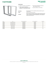
3.2.3 FC 301 vs. FC 302 Control Principle
FC 301 is a general purpose frequency converter for variable speed applications. The control principle is based on Voltage
Vector Control (VVC
plus
).
FC 301 can handle asynchronous motors only.
The current sensing principle in FC 301 is based on current measurement in the DC link or motor phase. The ground fault
protection on the motor side is solved by a de-saturation circuit in the IGBTs connected to the control board.
Short circuit behaviour on FC 301 depends on the current transducer in the positive DC link and the desaturation protection
with feedback from the 3 lower IGBT's and the brake.
M
L2 92
L1 91
L3 93
89(+)
88(-)
R+
82
R-
81
U 96
V 97
W 98
130BA192.12
InrushR inr
Load sharing -
De-saturation protection
Load sharing +
Brake
Resistor
Drive
Control
Board
Illustration 3.1 FC 301
FC 302 is a high performance frequency converter for demanding applications. The frequency converter can handle various
kinds of motor control principles such as U/f special motor mode, VVC
plus
or Flux Vector motor control.
FC 302 is able to handle Permanent Magnet Synchronous Motors (Brushless servo motors) as well as normal squirrel cage
asynchronous motors.
Short circuit behaviour on FC 302 depends on the 3 current transducers in the motor phases and the desaturation
protection with feedback from the brake.
Inrush
R inr
Load sharing -
Load sharing +
LC Filter -
(5A)
LC Filter +
(5A)
Brake
Resistor
130BA193.13
M
L2 92
L1 91
L3 93
89(+)
88(-)
R+
82
R-
81
U 96
V 97
W 98
P 14-50
Illustration 3.2 FC 302
Introduction to FC 300 FC 300 Design Guide
18 MG.33.BD.02 - VLT
®
is a registered Danfoss trademark
3
3

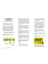
3.2.4
Control Structure in VVC
plus
Advanced Vector Control
Control structure in VVC
plus
open loop and closed loop configurations:
+
_
+
_
Cong. mode
Ref.
Process
P 1-00
High
+f max.
Low
-f max.
P 4-11
Motor speed
low limit (RPM)
P 4-12
Motor speed
low limit (Hz)
P 4-13
Motor speed
high limit (RPM)
P 4-14
Motor speed
high limit (Hz)
Motor
controller
Ramp
Speed
PID
P 7-20 Process feedback
1 source
P 7-22 Process feedback
2 source
P 7-00 Speed PID
feedback source
P 1-00
Cong. mode
P 4-19
Max. output freq.
-f max.
Motor
controller
P 4-19
Max. output freq.
+f max.
P 3-**
P 7-0*
130BA055.10
In the configuration shown in Illustration 3.3, 1-01 Motor Control Principle is set to “VVC
plus
[1]” and 1-00 Configuration Mode is
set to “Speed open loop [0]”. The resulting reference from the reference handling system is received and fed through the
ramp limitation and speed limitation before being sent to the motor control. The output of the motor control is then
limited by the maximum frequency limit.
If 1-00 Configuration Mode is set to “Speed closed loop [1]” the resulting reference will be passed from the ramp limitation
and speed limitation into a speed PID control. The Speed PID control parameters are located in the parameter group 7-0*.
The resulting reference from the Speed PID control is sent to the motor control limited by the frequency limit.
Select “Process [3]” in 1-00 Configuration Mode to use the process PID control for closed loop control of e.g. speed or
pressure in the controlled application. The Process PID parameters are located in parameter group 7-2* and 7-3*.
Introduction to FC 300 FC 300 Design Guide
MG.33.BD.02 - VLT
®
is a registered Danfoss trademark 19
3
3
/