Page is loading ...

OperatingGuide
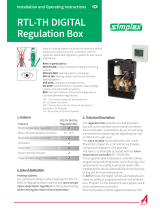
ECLComfort210/296/310,applicationA275/A375
1.0TableofContents
1.0TableofContents...............................................1
1.1Importantsafetyandproductinformation.....................2
2.0Installation........................................................5
2.1Beforeyoustart.....................................................5
2.2Identifyingthesystemtype......................................19
2.3Mounting...........................................................43
2.4Placingthetemperaturesensors................................46
2.5Electricalconnections.............................................48
2.6InsertingtheECLApplicationKey..............................75
2.7Checklist............................................................81
2.8Navigation,ECLApplicationKeyA275.........................82
3.0Dailyuse.........................................................90
3.1Howtonavigate...................................................90
3.2Understandingthecontrollerdisplay..........................91
3.3Ageneraloverview:Whatdothesymbolsmean?...........95
3.4Monitoringtemperaturesandsystem
components........................................................96
3.5Influenceoverview................................................98
3.6Manualcontrol.....................................................99
3.7Schedule..........................................................100
4.0Settingsoverview..........................................101
5.0Settings.........................................................104
5.1IntroductiontoSettings........................................104
5.2Flow(boiler)temperature......................................105
5.3Tanktemperature................................................110
5.4Roomlimit........................................................114
5.5Returnlimit.......................................................116
5.6Optimization......................................................122
5.7Boiler...............................................................128
5.8Controlparameters..............................................136
5.9Application.......................................................141
5.10Alarm..............................................................150
5.11Alarmoverview..................................................154
5.12Anti-bacteria......................................................155
6.0Commoncontrollersettings............................157
6.1Introductionto‘Commoncontrollersettings’..............157
6.2Time&Date.......................................................158
6.3Holiday............................................................159
6.4Inputoverview...................................................161
6.5Log.................................................................162
6.6Outputoverride..................................................163
6.7Keyfunctions.....................................................164
6.8System.............................................................166
7.0Miscellaneous................................................173
7.1ECA30/31setupprocedures.................................173
7.2Overridefunction................................................181
7.3Severalcontrollersinthesamesystem......................184
7.4Frequentlyaskedquestions....................................187
7.5Definitions........................................................190
7.6Type(ID6001),overview.......................................194
7.7ParameterIDoverview..........................................195
©Danfoss|2018.09VI.GU.L3.02|1

1.1Importantsafetyandproductinformation
1.1.1Importantsafetyandproductinformation
ThisInstallationGuideisassociatedwithECLApplicationKeyA275
(ordercodeno.087H3814).
TheECLKeyA275containstwosetsofapplications:onesetfor
A275(A275.1/A275.2/A275.3)andanothersetforA375(A375.1
/A375.2/A375.3).
TheapplicationsA275arefor1-burnersolutions.
TheapplicationsA375areformultipleburnersolutions.
Thefunctionscanberealizedin:
ECLComfort210(A275)forsimplesolutionsor
ECLComfort310(A275/A375)foradvancedsolutions,e.g.M-bus,
ModbusandEthernet(Internet)communication.
TheapplicationA275complieswithECLComfortcontroller210
and310asofsoftwareversion1.11(visibleatstart-upofthe
controllerandin‘Commoncontrollersettings’in‘System’).
AdditionaldocumentationforECLComfort210andaccessoriesis
availableonwww.ecl.doc.danfoss.com.
A275/A375navigationingeneral:
A275.1/A375.1A275.2/A375.2A275.3/A375.3
CircuitCircuitCircuit
11
2
1
23
Burnercontroloverview:
R2–R10=relaynos.inECL/ECA32
Seethesection‘Electricalconnections’formoredetailedinformation.
Applicationkeysmightbereleasedbeforealldisplaytextsare
translated.InthiscasethetextisinEnglish.
2|©Danfoss|2018.09
VI.GU.L3.02
OperatingGuideECLComfort210/296/310,applicationA275/A375

Automaticupdateofcontrollersoftware(firmware):
Thesoftwareofthecontrollerisupdatedautomaticallywhenthekey
isinserted(asofcontrollerversion1.11(ECL210/310)andversion
1.58(ECL296)).Thefollowinganimationwillbeshownwhenthe
softwareisbeingupdated:
Progressbar
Duringupdate:
•DonotremovetheKEY
Ifthekeyisremovedbeforethehour-glassisshown,youhave
tostartafresh.
•Donotdisconnectthepower
Ifthepowerisinterruptedwhenthehour-glassisshown,the
controllerwillnotwork.
•Manualupdateofcontrollersoftware(firmware):
Seethesection"Automatic/manualupdateoffirmware"
SafetyNote
Toavoidinjuryofpersonsanddamagestothedevice,itisabsolutely
necessarytoreadandobservetheseinstructionscarefully.
Necessaryassembly,start-up,andmaintenanceworkmustbe
performedbyqualifiedandauthorizedpersonnelonly.
Locallegislationsmustberespected.Thiscomprisesalsocable
dimensionsandtypeofisolation(doubleisolatedat230V).
AfusefortheECLComfortinstallationismax.10Atypically.
TheambienttemperaturerangesforECLComfortinoperationare:
ECLComfort210/310:0-55°C
ECLComfort296:0-45°C.
Exceedingthetemperaturerangecanresultinmalfunctions.
Installationmustbeavoidedifthereisariskforcondensation(dew).
Thewarningsignisusedtoemphasizespecialconditionsthatshould
betakenintoconsideration.
Thissymbolindicatesthatthisparticularpieceofinformationshould
bereadwithspecialattention.
AsthisOperatingGuidecoversseveralsystemtypes,specialsystem
settingswillbemarkedwithasystemtype.Allsystemtypesareshown
inthechapter:'Identifyingyoursystemtype'.
VI.GU.L3.02
©Danfoss|2018.09|3
OperatingGuideECLComfort210/296/310,applicationA275/A375

°C(degreesCelsius)isameasuredtemperaturevaluewhereasK
(Kelvin)oftenisusedfortemperaturedifferences.
TheIDno.isuniquefortheselectedparameter.
ExampleFirstdigitSeconddigitLastthreedigits
1117411174
-
Circuit1Parameterno.
12174
1
2
174
-
Circuit2Parameterno.
IfanIDdescriptionismentionedmorethanonce,itmeansthatthere
arespecialsettingsforoneormoresystemtypes.Itwillbemarked
withthesystemtypeinquestion(e.g.12174-A266.9).
ParametersindicatedwithanIDno.like"1x607"meanauniversal
parameter.
xstandsforcircuit/parametergroup.
DisposalNote
Thisproductshouldbedismantledanditscomponents
sorted,ifpossible,invariousgroupsbeforerecycling
ordisposal.
Alwaysfollowthelocaldisposalregulations.
4|©Danfoss|2018.09
VI.GU.L3.02
OperatingGuideECLComfort210/296/310,applicationA275/A375

2.0Installation
2.1Beforeyoustart
TheapplicationA275.1isveryflexible.Thesearethebasic
principles:
Heating(circuit1):
Typically,theboilertemperatureisadjustedaccordingtoyour
requirements.TheboilertemperaturesensorS3isthemost
importantsensor.Itmustbeplacedcorrectlyinordertomeasure
theboilertemperature.ThedesiredboilertemperatureatS3is
calculatedintheECLcontroller,basedontheoutdoortemperature
(S1).Thelowertheoutdoortemperature,thehigherthedesired
boilertemperature.Theboilertemperatureisalsotheflow
temperatureinthedirectconnectedheatingcircuit.
Bymeansofaweekschedule(upto3‘Comfort’periods/day),the
heatingcircuitcanbein‘Comfort’or‘Saving’mode(twodifferent
temperaturevaluesforthedesiredroomtemperature).In'Saving'
modea'Totalstop'functioncanbeselectedinordertoswitchOFF
theheating.
TheburnerisswitchedONwhentheboilertemperatureis
lowerthanthedesiredboilertemperatureandswitchedOFF
whentheboilertemperatureishigherthanthedesiredboiler
temperature.AswitchingdifferencedeterminestheON/OFF
control.Furthermore,theboilerprotectionfunctionwillonly
switchONthecirculationpumpiftheboilertemperaturegets
aboveaminimumtemperature.AminimumON-timecanbesetfor
theburnerinordertoincreasetheboiler'sefficiency.
Thereturntemperature(S5)totheboilershouldnotbetoo
high(condensingboiler)ortoolow(oilorgasfiredboiler).Ifso,
thedesiredboilertemperaturecanbedecreasedorincreased.
Furthermore,thereturntemperaturelimitationcanbedependent
oftheoutdoortemperature.Typically,thelowertheoutdoor
temperature,thehighertheacceptedreturntemperature.
Ifthemeasuredroomtemperature(measuredbyS7ortheremote
controlunitECA30)doesnotequalthedesiredroomtemperature,
thedesiredboilertemperaturecanbeadjusted.
Thecirculationpump(P1)isONatheatdemandoratfrost
protection.
TheheatingcanbeswitchedOFFiftheoutdoortemperaturegets
higherthanasetvalue.
TypicalA275.1application:
*Pressurereliefvalve
Theshowndiagramisafundamentalandsimplifiedexampleanddoes
notcontainallcomponentsthatarenecessaryinasystem.
AllnamedcomponentsareconnectedtotheECLComfortcontroller.
Listofcomponents:
S1
Outdoortemperaturesensor
S3
Boilertemperaturesensor
S5Returntemperaturesensor
S7
Roomtemperaturesensor/ECA30
P1
Circulationpump
B1Burner
A1
Alarm
Thecontrollerispre-programmedwithfactorysettingsthatareshown
intherelevantchaptersofthisguide.
VI.GU.L3.02
©Danfoss|2018.09|5
OperatingGuideECLComfort210/296/310,applicationA275/A375

TheapplicationA275.2isveryflexible.Thesearethebasic
principles:
Heating(circuit1):
Typically,theboilertemperatureisadjustedaccordingtoyour
requirements.TheboilertemperaturesensorS3isthemost
importantsensor.Itmustbeplacedcorrectlyinordertomeasure
theboilertemperature.ThedesiredboilertemperatureatS3is
calculatedintheECLcontroller,basedontheoutdoortemperature
(S1).Thelowertheoutdoortemperature,thehigherthedesired
boilertemperature.Theboilertemperatureisalsotheflow
temperatureinthedirectconnectedheatingcircuit.
Bymeansofaweekschedule(upto3‘Comfort’periods/day),the
heatingcircuitcanbein‘Comfort’or‘Saving’mode(twodifferent
temperaturevaluesforthedesiredroomtemperature).In'Saving'
modea'Totalstop'functioncanbeselectedinordertoswitchOFF
theheating.
TheburnerisswitchedONwhentheboilertemperatureis
lowerthanthedesiredboilertemperatureandswitchedOFF
whentheboilertemperatureishigherthanthedesiredboiler
temperature.AswitchingdifferencedeterminestheON/OFF
control.Furthermore,theboilerprotectionfunctionwillonly
switchONthecirculationpumpiftheboilertemperaturegets
aboveaminimumtemperature.AminimumON-timecanbesetfor
theburnerinordertoincreasetheboiler'sefficiency.
Thereturntemperature(S5)totheboilershouldnotbetoo
high(condensingboiler)ortoolow(oilorgasfiredboiler).Ifso,
thedesiredboilertemperaturecanbedecreasedorincreased.
Furthermore,thereturntemperaturelimitationcanbedependent
oftheoutdoortemperature.Typically,thelowertheoutdoor
temperature,thehighertheacceptedreturntemperature.
Ifthemeasuredroomtemperature(measuredbyS7ortheremote
controlunitECA30)doesnotequalthedesiredroomtemperature,
thedesiredboilertemperaturecanbeadjusted.
Thecirculationpump(P1)isONatheatdemandoratfrost
protection.
TheheatingcanbeswitchedOFFiftheoutdoortemperaturegets
higherthanasetvalue.
TypicalA275.2application:
*Pressurereliefvalve
Theshowndiagramisafundamentalandsimplifiedexampleanddoes
notcontainallcomponentsthatarenecessaryinasystem.
AllnamedcomponentsareconnectedtotheECLComfortcontroller.
Listofcomponents:
S1
Outdoortemperaturesensor
S3
Boilertemperaturesensor
S5Returntemperaturesensor
S6
DHWtanktemperaturesensor
S7
Roomtemperaturesensor/ECA30
P1
Circulationpump,heating
B1Burner
P3
DHWheatingpump
A1
Alarm
Thecontrollerispre-programmedwithfactorysettingsthatareshown
intherelevantchaptersofthisguide.
6|©Danfoss|2018.09
VI.GU.L3.02
OperatingGuideECLComfort210/296/310,applicationA275/A375

TheapplicationA275.2isveryflexible.Thesearethebasic
principles:
DHW(circuit2):
Bymeansofaweekschedule(upto3‘Comfort’periods/day),the
DHWcircuitcanbein‘Comfort’or‘Saving’mode(twodifferent
temperaturevaluesfordesiredDHWtemperature).
IfthemeasuredDHWtemperature(S6)islowerthanthedesired
DHWtemperature,theDHWheatingprocedurestarts:
•ThecirculationpumpP1intheheatingcircuitisswitchedOFF
•TheDHWheatingpumpP3isswitchedON
•ThedesiredboilertemperatureatS3isincreased.
Thedesiredboilertemperatureistypically10-15degreeshigher
thanthedesiredDHWtemperature.
WhenthemeasuredDHWtemperature(S6)getshigherthanthe
desiredDHWtemperature,theDHWheatingpump(P3)isswitched
OFF.StartandstopdifferencesdeterminetheON/OFFcontrol.A
post-runtimecanbeset.
Ananti-bacteriafunctionisavailableforactivationontheselected
daysoftheweek.
TheDHWheatinghaspriority,i.e.pumpP3isONandpumpP1is
OFF.Iftheapplicationhasachangeovervalve(priorityvalve)for
theDHWheating,thecirculationpumpP1isstillONduringDHW
heating.
TypicalA275.2application:
*Pressurereliefvalve
Theshowndiagramisafundamentalandsimplifiedexampleanddoes
notcontainallcomponentsthatarenecessaryinasystem.
AllnamedcomponentsareconnectedtotheECLComfortcontroller.
Listofcomponents:
S1
Outdoortemperaturesensor
S3
Boilertemperaturesensor
S5Returntemperaturesensor
S6
DHWtanktemperaturesensor
S7
Roomtemperaturesensor/ECA30
P1
Circulationpump,heating
B1Burner
P3
DHWheatingpump
A1
Alarm
Thecontrollerispre-programmedwithfactorysettingsthatareshown
intherelevantchaptersofthisguide.
VI.GU.L3.02
©Danfoss|2018.09|7
OperatingGuideECLComfort210/296/310,applicationA275/A375

TheapplicationA275.3isveryflexible.Thesearethebasic
principles:
Heating(circuit1):
Typically,theboilertemperatureisadjustedaccordingtoyour
requirements.TheboilertemperaturesensorS3isthemost
importantsensor.Itmustbeplacedcorrectlyinordertomeasure
theboilertemperature.ThedesiredboilertemperatureatS3is
calculatedintheECLcontroller,basedontheoutdoortemperature
(S1).Thelowertheoutdoortemperature,thehigherthedesired
boilertemperature.Theboilertemperatureisalsotheflow
temperatureinthedirectconnectedheatingcircuit.
Bymeansofaweekschedule(upto3‘Comfort’periods/day),the
heatingcircuitcanbein‘Comfort’or‘Saving’mode(twodifferent
temperaturevaluesforthedesiredroomtemperature).In'Saving'
modea'Totalstop'functioncanbeselectedinordertoswitchOFF
theheating.
TheburnerisswitchedONwhentheboilertemperatureis
lowerthanthedesiredboilertemperatureandswitchedOFF
whentheboilertemperatureishigherthanthedesiredboiler
temperature.AswitchingdifferencedeterminestheON/OFF
control.Furthermore,theboilerprotectionfunctionwillonly
switchONthecirculationpumpiftheboilertemperaturegets
aboveaminimumtemperature.AminimumON-timecanbesetfor
theburnerinordertoincreasetheboiler'sefficiency.
Thereturntemperature(S5)totheboilershouldnotbetoo
high(condensingboiler)ortoolow(oilorgasfiredboiler).Ifso,
thedesiredboilertemperaturecanbedecreasedorincreased.
Furthermore,thereturntemperaturelimitationcanbedependent
oftheoutdoortemperature.Typically,thelowertheoutdoor
temperature,thehighertheacceptedreturntemperature.
Ifthemeasuredroomtemperature(measuredbyS7ortheremote
controlunitECA30)doesnotequalthedesiredroomtemperature,
thedesiredboilertemperaturecanbeadjusted.
Thecirculationpump(P1)isONatheatdemandoratfrost
protection.
TheheatingcanbeswitchedOFFiftheoutdoortemperaturegets
higherthanasetvalue.
TypicalA275.3application:
*Pressurereliefvalve
Theshowndiagramisafundamentalandsimplifiedexampleanddoes
notcontainallcomponentsthatarenecessaryinasystem.
AllnamedcomponentsareconnectedtotheECLComfortcontroller.
Listofcomponents:
S1
Outdoortemperaturesensor
S2Returntemperaturesensor,circuit2
S3
Boilertemperaturesensor,circuit1
S4
Flowtemperaturesensor,circuit2
S5Returntemperaturesensor,circuit1
S6
DHWtanktemperaturesensor
S7
Roomtemperaturesensor/ECA30,circuit1
S8
Roomtemperaturesensor/ECA30,circuit2
M2
Motorizedcontrolvalve,circuit2
P1
Circulationpump,circuit1
B1Burner
P3
DHWheatingpump,circuit3
P4
Circulationpump,circuit2
Thecontrollerispre-programmedwithfactorysettingsthatareshown
intherelevantchaptersofthisguide.
8|©Danfoss|2018.09
VI.GU.L3.02
OperatingGuideECLComfort210/296/310,applicationA275/A375

TheapplicationA275.3isveryflexible.Thesearethebasic
principles:
Heating(circuit2):
Typically,theflowtemperatureisadjustedaccordingtoyour
requirements.TheflowtemperaturesensorS4isthemost
importantsensor.ThedesiredflowtemperatureatS4iscalculated
intheECLcontroller,basedontheoutdoortemperature(S1).
Thelowertheoutdoortemperature,thehigherthedesiredflow
temperature.
Bymeansofaweekschedule(upto3‘Comfort’periods/day),the
heatingcircuitcanbein‘Comfort’or‘Saving’mode(twodifferent
temperaturevaluesforthedesiredroomtemperature).In'Saving'
modea'Totalstop'functioncanbeselectedinordertoswitchOFF
theheating.
ThemotorizedcontrolvalveM2isopenedgraduallywhentheflow
temperature,S4,islowerthanthedesiredflowtemperatureand
viceversa.
ThedesiredflowtemperatureatS4willtypicallydeterminethe
desiredboilertemperature(S3).
Thereturntemperature(S2)canbelimited.Ifso,thedesiredflow
temperatureatS4canbedecreasedorincreased.
Furthermore,thereturntemperaturelimitationcanbedependent
oftheoutdoortemperature.Typically,thelowertheoutdoor
temperature,thehighertheacceptedreturntemperature.
Ifthemeasuredroomtemperature(measuredbyS8ortheremote
controlunitECA30)doesnotequalthedesiredroomtemperature,
thedesiredflowtemperaturecanbeadjusted.
Thecirculationpump(P4)isONatheatdemandoratfrost
protection.
TheheatingcanbeswitchedOFFwhentheoutdoortemperatureis
higherthanaselectablevalueoraDHWheatingpriorityispresent.
TypicalA275.3application:
*Pressurereliefvalve
Theshowndiagramisafundamentalandsimplifiedexampleanddoes
notcontainallcomponentsthatarenecessaryinasystem.
AllnamedcomponentsareconnectedtotheECLComfortcontroller.
Listofcomponents:
S1
Outdoortemperaturesensor
S2Returntemperaturesensor,circuit2
S3
Boilertemperaturesensor,circuit1
S4
Flowtemperaturesensor,circuit2
S5Returntemperaturesensor,circuit1
S6
DHWtanktemperaturesensor
S7
Roomtemperaturesensor/ECA30,circuit1
S8
Roomtemperaturesensor/ECA30,circuit2
M2
Motorizedcontrolvalve,circuit2
P1
Circulationpump,circuit1
B1Burner
P3
DHWheatingpump,circuit3
P4
Circulationpump,circuit2
Thecontrollerispre-programmedwithfactorysettingsthatareshown
intherelevantchaptersofthisguide.
VI.GU.L3.02
©Danfoss|2018.09|9
OperatingGuideECLComfort210/296/310,applicationA275/A375

TheapplicationA275.3isveryflexible.Thesearethebasic
principles:
DHW(circuit3):
Bymeansofaweekschedule(upto3‘Comfort’periods/day),the
DHWcircuitcanbein‘Comfort’or‘Saving’mode(twodifferent
temperaturevaluesfordesiredDHWtemperature).
IfthemeasuredDHWtemperature(S6)islowerthanthedesired
DHWtemperature,theDHWheatingprocedurestarts:
•ThecirculationpumpP1intheheatingcircuitisswitchedOFF
•TheDHWheatingpumpP3isswitchedON
•ThedesiredboilertemperatureatS3isincreased.
Thedesiredboilertemperatureistypically10-15degreeshigher
thanthedesiredDHWtemperature.
WhenthemeasuredDHWtemperature(S6)getshigherthanthe
desiredDHWtemperature,theDHWheatingpump(P3)isswitched
OFF.StartandstopdifferencesdeterminetheON/OFFcontrol.A
post-runtimecanbeset.
Ananti-bacteriafunctionisavailableforactivationontheselected
daysoftheweek.
TheDHWheatinghaspriority,i.e.pumpP3isONandpumpP1is
OFF.Iftheapplicationhasachangeovervalve(priorityvalve)for
theDHWheating,thecirculationpumpP1isstillONduringDHW
heating.
TypicalA275.3application:
*Pressurereliefvalve
Theshowndiagramisafundamentalandsimplifiedexampleanddoes
notcontainallcomponentsthatarenecessaryinasystem.
AllnamedcomponentsareconnectedtotheECLComfortcontroller.
Listofcomponents:
S1
Outdoortemperaturesensor
S2Returntemperaturesensor,circuit2
S3
Boilertemperaturesensor,circuit1
S4
Flowtemperaturesensor,circuit2
S5Returntemperaturesensor,circuit1
S6
DHWtanktemperaturesensor
S7
Roomtemperaturesensor/ECA30,circuit1
S8
Roomtemperaturesensor/ECA30,circuit2
M2
Motorizedcontrolvalve,circuit2
P1
Circulationpump,circuit1
B1Burner
P3
DHWheatingpump,circuit3
P4
Circulationpump,circuit2
Thecontrollerispre-programmedwithfactorysettingsthatareshown
intherelevantchaptersofthisguide.
10|©Danfoss|2018.09
VI.GU.L3.02
OperatingGuideECLComfort210/296/310,applicationA275/A375

ApplicationA275ingeneral:
Unusedinputcan,bymeansofanoverrideswitch,beusedto
overridethescheduletoafixed'Comfort'or'Saving'mode.
ModbuscommunicationtoaSCADAsystemcanbeestablished.
Alarm,A275.1andA275.2:
AlarmA1(relayR4)andthealarmsymbol(
)canbeactivated:
•ifatemperaturesensororitsconnectiondisconnects/
shortcircuits.
Alarm,A275.3:
Thealarmsymbol(
)canbeactivated:
•ifatemperaturesensororitsconnectiondisconnects/
shortcircuits.
•iftheactualflowtemperatureatS4(heatingcircuit2),differs
fromthedesiredflowtemperature.
VI.GU.L3.02
©Danfoss|2018.09|11
OperatingGuideECLComfort210/296/310,applicationA275/A375

TheapplicationA375.1isveryflexible.Thesearethebasic
principles:
TheapplicationsA375.1/A375.2/A375.3canON/OFFcontrolup
to8burnersteps.
InapplicationA375.1thefirst4burnerstepsarecontrolledby
relaysintheECL310.Thenext,max.4burnersteps,arecontrolled
byrelaysintheextensionmoduleECA32(placedinthebasepart
oftheECL310).
Heating(circuit1):
Typically,thecommonboilertemperatureisadjustedaccordingto
yourrequirements.TheboilertemperaturesensorS3isthemost
importantsensor.Itmustbeplacedcorrectlyinordertomeasure
thecommonboilertemperature.Thedesiredboilertemperature
atS3iscalculatedintheECLcontroller,basedontheoutdoor
temperature(S1).Thelowertheoutdoortemperature,thehigher
thedesiredboilertemperature.Theboilertemperatureisalsothe
flowtemperatureinthedirectconnectedheatingcircuit.
Bymeansofaweekschedule(upto3‘Comfort’periods/day),the
heatingcircuitcanbein‘Comfort’or‘Saving’mode(twodifferent
temperaturevaluesforthedesiredroomtemperature).In'Saving'
modea'Totalstop'functioncanbeselectedinordertoswitchOFF
theheating.
ThefirstburnerstepisswitchedONwhenthecommonboiler
temperatureislowerthanthedesiredboilertemperature.The
controllerobservesthecommonboilertemperatureandswitches
ONthenextburnerstepifthecommonboilertemperaturedoes
notincreasesatisfactorily.TheswitchingOFFprocedureofburner
stepsisviceversa.AswitchingdifferencedeterminestheON/OFF
control.
Theburnerscanbecontrolledin:
•fixedsequence(example:Always1-2-3-4-5)or
•automaticrotatingsequence(example:Firstperiod:1-2-3-4-5,
secondperiod:2-3-4-5-1,thirdperiod:3-4-5-1-2andsoon)
•semi-automaticrotatingsequence(example:Firstperiod:1,
2-3-4-5,secondperiod:1,3-4-5-2,thirdperiod:1,4-5-2-3and
soon)
Furthermore,theboilerprotectionfunctionwillswitchONthe
circulationpumpwhentheboilertemperaturegetsabovea
minimumvalue.AminimumON-timecanbesetfortheburnerin
ordertoincreasetheboiler'sefficiency.
Thereturntemperature(S5)totheboilershouldnotbetoo
high(condensingboiler)ortoolow(oilorgasfiredboiler).Ifso,
thedesiredboilertemperaturecanbedecreasedorincreased.
Furthermore,thereturntemperaturelimitationcanbedependent
oftheoutdoortemperature.Typically,thelowertheoutdoor
temperature,thehighertheacceptedreturntemperature.
Ifthemeasuredroomtemperature(S7orRemotecontrolunitECA
30)doesnotequalthedesiredroomtemperature,thedesired
boilertemperaturecanbeadjusted.
Thecirculationpump(P1)isONatheatdemandoratfrost
protection.
TheheatingcanbeswitchedOFFwhentheoutdoortemperatureis
higherthanasetvalue.
Thedesiredcommonboilertemperaturecan,viaS10,becontrolled
bymeansofanexternalvoltageintherange0-10volt.
TypicalA375.1application:
*Pressurereliefvalve
Theshowndiagramisafundamentalandsimplifiedexampleanddoes
notcontainallcomponentsthatarenecessaryinasystem.
AllnamedcomponentsareconnectedtotheECLComfortcontroller.
Listofcomponents:
S1
Outdoortemperaturesensor
S3
Commonboilertemperaturesensor
S5Returntemperaturesensor
S7
Roomtemperaturesensor/ECA30
(S10)
(Externaltemperaturecontrol,notillustrated)
P1
Circulationpump
B1–B8Burner1...8
A1
Alarm
Thecontrollerispre-programmedwithfactorysettingsthatareshown
intherelevantchaptersofthisguide.
Boilersequencerotation/shifttakesplaceatmidnight.
12|©Danfoss|2018.09
VI.GU.L3.02
OperatingGuideECLComfort210/296/310,applicationA275/A375

TheapplicationA375.2isveryflexible.Thesearethebasic
principles:
TheapplicationsA375.1/A375.2/A375.3canON/OFFcontrolup
to8burnersteps.
InapplicationA375.2thefirst2burnerstepsarecontrolledby
relaysintheECL310.Thenext,max.4burnersteps,arecontrolled
byrelaysintheextensionmoduleECA32(placedinthebasepartof
theECL310).Thelast,max.2burnerstepsarecontrolledbytriacs
intheECL310.Auxillaryrelaysmustbeconnectedtothetriacs.
Heating(circuit1):
Typically,thecommonboilertemperatureisadjustedaccordingto
yourrequirements.TheboilertemperaturesensorS3isthemost
importantsensor.Itmustbeplacedcorrectlyinordertomeasure
thecommonboilertemperature.Thedesiredboilertemperature
atS3iscalculatedintheECLcontroller,basedontheoutdoor
temperature(S1).Thelowertheoutdoortemperature,thehigher
thedesiredboilertemperature.Theboilertemperatureisalsothe
flowtemperatureinthedirectconnectedheatingcircuit.
Bymeansofaweekschedule(upto3‘Comfort’periods/day),the
heatingcircuitcanbein‘Comfort’or‘Saving’mode(twodifferent
temperaturevaluesforthedesiredroomtemperature).In'Saving'
modea'Totalstop'functioncanbeselectedinordertoswitchOFF
theheating.
ThefirstburnerstepisswitchedONwhenthecommonboiler
temperatureislowerthanthedesiredboilertemperature.The
controllerobservesthecommonboilertemperatureandswitches
ONthenextburnerstepifthecommonboilertemperaturedoes
notincreasesatisfactorily.TheswitchingOFFprocedureofburner
stepsisviceversa.AswitchingdifferencedeterminestheON/OFF
control.
Theburnerscanbecontrolledin:
•fixedsequence(example:Always1-2-3-4-5)or
•automaticrotatingsequence(example:Firstperiod:1-2-3-4-5,
secondperiod:2-3-4-5-1,thirdperiod:3-4-5-1-2andsoon)
•semi-automaticrotatingsequence(example:Firstperiod:1,
2-3-4-5,secondperiod:1,3-4-5-2,thirdperiod:1,4-5-2-3and
soon)
Furthermore,theboilerprotectionfunctionwillswitchONthe
circulationpumpwhentheboilertemperaturegetsabovea
minimumvalue.AminimumON-timecanbesetfortheburnerin
ordertoincreasetheboiler'sefficiency.
Thereturntemperature(S5)totheboilershouldnotbetoo
high(condensingboiler)ortoolow(oilorgasfiredboiler).Ifso,
thedesiredboilertemperaturecanbedecreasedorincreased.
Furthermore,thereturntemperaturelimitationcanbedependent
oftheoutdoortemperature.Typically,thelowertheoutdoor
temperature,thehighertheacceptedreturntemperature.
Ifthemeasuredroomtemperature(S7orRemotecontrolunitECA
30)doesnotequalthedesiredroomtemperature,thedesired
boilertemperaturecanbeadjusted.
Thecirculationpump(P1)isONatheatdemandoratfrost
protection.
TheheatingcanbeswitchedOFFwhentheoutdoortemperatureis
higherthanasetvalue.
Thedesiredcommonboilertemperaturecan,viaS10,becontrolled
bymeansofanexternalvoltageintherange0-10volt.
TypicalA375.2application:
*Pressurereliefvalve
Theshowndiagramisafundamentalandsimplifiedexampleanddoes
notcontainallcomponentsthatarenecessaryinasystem.
AllnamedcomponentsareconnectedtotheECLComfortcontroller.
Listofcomponents:
S1
Outdoortemperaturesensor
S3
Commonboilertemperaturesensor
S5Returntemperaturesensor
S6
DHWtanktemperaturesensor
S7
Roomtemperaturesensor/ECA30
(S10)
(Externaltemperaturecontrol,notillustrated)
P1
Circulationpump,heating
B1–B8Burner1...8
P3
DHWheatingpump
A1
Alarm
Thecontrollerispre-programmedwithfactorysettingsthatareshown
intherelevantchaptersofthisguide.
Boilersequencerotation/shifttakesplaceatmidnight.
VI.GU.L3.02
©Danfoss|2018.09|13
OperatingGuideECLComfort210/296/310,applicationA275/A375

TheapplicationA375.2isveryflexible.Thesearethebasic
principles:
DHW(circuit2):
Bymeansofaweekschedule(upto3‘Comfort’periods/day),the
DHWcircuitcanbein‘Comfort’or‘Saving’mode(twodifferent
temperaturevaluesfordesiredDHWtemperature).
IfthemeasuredDHWtemperature(S6)islowerthanthedesired
DHWtemperature,theDHWheatingprocedurestarts:
•ThecirculationpumpP1intheheatingcircuitisswitchedOFF
•TheDHWheatingpumpP3isswitchedON
•ThedesiredboilertemperatureatS3isincreased.
Thedesiredboilertemperatureistypically10-15degreeshigher
thanthedesiredDHWtemperature.
WhenthemeasuredDHWtemperature(S6)getshigherthanthe
desiredDHWtemperature,theDHWheatingpump(P3)isswitched
OFF.StartandstopdifferencesdeterminetheON/OFFcontrol.A
post-runtimecanbeset.
TheDHWcirculationpump(P4)hasaweekscheduleforupto3
ONperiodsperday.
Ananti-bacteriafunctionisavailableforactivationonselected
daysoftheweek.
TheDHWheatingcanhavepriority,i.e.pumpP3isONandpump
P1isOFF.Iftheapplicationhasachangeovervalve(priorityvalve)
fortheDHWheating,thecirculationpumpP1isstillONduring
DHWheating.
TypicalA375.2application:
*Pressurereliefvalve
Theshowndiagramisafundamentalandsimplifiedexampleanddoes
notcontainallcomponentsthatarenecessaryinasystem.
AllnamedcomponentsareconnectedtotheECLComfortcontroller.
Listofcomponents:
S1
Outdoortemperaturesensor
S3
Commonboilertemperaturesensor
S5Returntemperaturesensor
S6
DHWtanktemperaturesensor
S7
Roomtemperaturesensor/ECA30
(S10)
(Externaltemperaturecontrol,notillustrated)
P1
Circulationpump,heating
B1–B8Burner1...8
P3
DHWheatingpump
A1
Alarm
Thecontrollerispre-programmedwithfactorysettingsthatareshown
intherelevantchaptersofthisguide.
14|©Danfoss|2018.09
VI.GU.L3.02
OperatingGuideECLComfort210/296/310,applicationA275/A375

TheapplicationA375.3isveryflexible.Thesearethebasic
principles:
TheapplicationsA375.1/A375.2/A375.3canON/OFFcontrolup
to8burnersteps.
InapplicationA375.3thefirst2burnerstepsarecontrolledby
relaysintheECL310.Thenext,max.4burnersteps,arecontrolled
byrelaysintheextensionmoduleECA32(placedinthebasepartof
theECL310).Thelast,max.2burnerstepsarecontrolledbytriacs
intheECL310.Auxillaryrelaysmustbeconnectedtothetriacs.
Heating(circuit1):
Typically,thecommonboilertemperatureisadjustedaccordingto
yourrequirements.TheboilertemperaturesensorS3isthemost
importantsensor.Itmustbeplacedcorrectlyinordertomeasure
thecommonboilertemperature.Thedesiredboilertemperature
atS3iscalculatedintheECLcontroller,basedontheoutdoor
temperature(S1).Thelowertheoutdoortemperature,thehigher
thedesiredboilertemperature.Theboilertemperatureisalsothe
flowtemperatureinthedirectconnectedheatingcircuit.
Bymeansofaweekschedule(upto3‘Comfort’periods/day),the
heatingcircuitcanbein‘Comfort’or‘Saving’mode(twodifferent
temperaturevaluesforthedesiredroomtemperature).In'Saving'
modea'Totalstop'functioncanbeselectedinordertoswitchOFF
theheating.
ThefirstburnerstepisswitchedONwhenthecommonboiler
temperatureislowerthanthedesiredboilertemperature.The
controllerobservesthecommonboilertemperatureandswitches
ONthenextburnerstepifthecommonboilertemperaturedoes
notincreasesatisfactorily.TheswitchingOFFprocedureofburner
stepsisviceversa.AswitchingdifferencedeterminestheON/OFF
control.
Theburnerscanbecontrolledin:
•fixedsequence(example:Always1-2-3-4-5)or
•automaticrotatingsequence(example:Firstperiod:1-2-3-4-5,
secondperiod:2-3-4-5-1,thirdperiod:3-4-5-1-2andsoon)
•semi-automaticrotatingsequence(example:Firstperiod:1,
2-3-4-5,secondperiod:1,3-4-5-2,thirdperiod:1,4-5-2-3and
soon)
Furthermore,theboilerprotectionfunctionwillswitchONthe
circulationpumpwhentheboilertemperaturegetsabovea
minimumvalue.AminimumON-timecanbesetfortheburnerin
ordertoincreasetheboiler'sefficiency.
Thereturntemperature(S5)totheboilershouldnotbetoo
high(condensingboiler)ortoolow(oilorgasfiredboiler).Ifso,
thedesiredboilertemperaturecanbedecreasedorincreased.
Furthermore,thereturntemperaturelimitationcanbedependent
oftheoutdoortemperature.Typically,thelowertheoutdoor
temperature,thehighertheacceptedreturntemperature.
Ifthemeasuredroomtemperature(S7orRemotecontrolunitECA
30)doesnotequalthedesiredroomtemperature,thedesired
boilertemperaturecanbeadjusted.
Thecirculationpump(P1)isONatheatdemandoratfrost
protection.
TheheatingcanbeswitchedOFFwhentheoutdoortemperatureis
higherthanasetvalue.
Thedesiredcommonboilertemperaturecan,viaS10,becontrolled
bymeansofanexternalvoltageintherange0-10volt.
TypicalA375.3application:
*Pressurereliefvalve
Theshowndiagramisafundamentalandsimplifiedexampleanddoes
notcontainallcomponentsthatarenecessaryinasystem.
AllnamedcomponentsareconnectedtotheECLComfortcontroller.
Listofcomponents:
S1
Outdoortemperaturesensor
S2Returntemperaturesensor,circuit2
S3
Commonboilertemperaturesensor,circuit1
S4
Flowtemperaturesensor,circuit2
S5Returntemperaturesensor,circuit1
S7
Roomtemperaturesensor/ECA30,circuit1
S8
Roomtemperaturesensor/ECA30,circuit2
(S10)
(Externaltemperaturecontrol,notillustrated)
M2
Motorizedcontrolvalve,circuit2
P1
Circulationpump,circuit1
B1–B8Burner1...8
P3
DHWheatingpump,circuit3
A1
Alarm
Thecontrollerispre-programmedwithfactorysettingsthatareshown
intherelevantchaptersofthisguide.
Boilersequencerotation/shifttakesplaceatmidnight.
VI.GU.L3.02
©Danfoss|2018.09|15
OperatingGuideECLComfort210/296/310,applicationA275/A375

TheapplicationA375.3isveryflexible.Thesearethebasic
principles:
Heating(circuit2):
Typically,theflowtemperatureisadjustedaccordingtoyour
requirements.TheflowtemperaturesensorS4isthemost
importantsensor.ThedesiredflowtemperatureatS4iscalculated
intheECLcontroller,basedontheoutdoortemperature(S1).
Thelowertheoutdoortemperature,thehigherthedesiredflow
temperature.
Bymeansofaweekschedule(upto3‘Comfort’periods/day),the
heatingcircuitcanbein‘Comfort’or‘Saving’mode(twodifferent
temperaturevaluesforthedesiredroomtemperature).In'Saving'
modea'Totalstop'functioncanbeselectedinordertoswitchOFF
theheating.
ThemotorizedcontrolvalveM2isopenedgraduallywhentheflow
temperature,S4,islowerthanthedesiredflowtemperatureand
viceversa.
ThedesiredflowtemperatureatS4willtypicallydeterminethe
desiredboilertemperature(S3).
Thereturntemperature(S2)canbelimited.Ifso,thedesiredflow
temperatureatS4canbedecreasedorincreased.
Furthermore,thereturntemperaturelimitationcanbedependent
oftheoutdoortemperature.Typically,thelowertheoutdoor
temperature,thehighertheacceptedreturntemperature.
Ifthemeasuredroomtemperature(measuredbyS8ortheremote
controlunitECA30)doesnotequalthedesiredroomtemperature,
thedesiredflowtemperaturecanbeadjusted.
Thecirculationpump(P4)isONatheatdemandoratfrost
protection.
TheheatingcanbeswitchedOFFwhentheoutdoortemperatureis
higherthanaselectablevalueoraDHWheatingpriorityispresent.
TypicalA375.3application:
*Pressurereliefvalve
Theshowndiagramisafundamentalandsimplifiedexampleanddoes
notcontainallcomponentsthatarenecessaryinasystem.
AllnamedcomponentsareconnectedtotheECLComfortcontroller.
Listofcomponents:
S1
Outdoortemperaturesensor
S2Returntemperaturesensor,circuit2
S3
Commonboilertemperaturesensor,circuit1
S4
Flowtemperaturesensor,circuit2
S5Returntemperaturesensor,circuit1
S7
Roomtemperaturesensor/ECA30,circuit1
S8
Roomtemperaturesensor/ECA30,circuit2
(S10)
(Externaltemperaturecontrol,notillustrated)
M2
Motorizedcontrolvalve,circuit2
P1
Circulationpump,circuit1
B1–B8Burner1...8
P3
DHWheatingpump,circuit3
A1
Alarm
Thecontrollerispre-programmedwithfactorysettingsthatareshown
intherelevantchaptersofthisguide.
16|©Danfoss|2018.09
VI.GU.L3.02
OperatingGuideECLComfort210/296/310,applicationA275/A375

TheapplicationA375.3isveryflexible.Thesearethebasic
principles:
DHW(circuit3):
Bymeansofaweekschedule(upto3‘Comfort’periods/day),the
DHWcircuitcanbein‘Comfort’or‘Saving’mode(twodifferent
temperaturevaluesfordesiredDHWtemperature)
.IfthemeasuredDHWtemperature(S6)islowerthanthedesired
DHWtemperature,theDHWheatingprocedurestarts:
•ThecirculationpumpP1intheheatingcircuitisswitchedOFF
•TheDHWheatingpumpP3isswitchedON
•ThedesiredboilertemperatureatS3isincreased.
Thedesiredboilertemperatureistypically10-15degreeshigher
thanthedesiredDHWtemperature.
WhenthemeasuredDHWtemperature(S6)getshigherthanthe
desiredDHWtemperature,theDHWheatingpump(P3)isswitched
OFF.StartandstopdifferencesdeterminetheON/OFFcontrol.A
post-runtimecanbeset.
Ananti-bacteriafunctionisavailableforactivationonselected
daysoftheweek.
TheDHWheatingcanhavepriority,i.e.pumpP3isONandpump
P1isOFF.Iftheapplicationhasachangeovervalve(priorityvalve)
fortheDHWheating,thecirculationpumpP1isstillONduring
DHWheating.
TypicalA375.3application:
*Pressurereliefvalve
Theshowndiagramisafundamentalandsimplifiedexampleanddoes
notcontainallcomponentsthatarenecessaryinasystem.
AllnamedcomponentsareconnectedtotheECLComfortcontroller.
Listofcomponents:
S1
Outdoortemperaturesensor
S2Returntemperaturesensor,circuit2
S3
Commonboilertemperaturesensor,circuit1
S4
Flowtemperaturesensor,circuit2
S5Returntemperaturesensor,circuit1
S7
Roomtemperaturesensor/ECA30,circuit1
S8
Roomtemperaturesensor/ECA30,circuit2
(S10)
(Externaltemperaturecontrol,notillustrated)
M2
Motorizedcontrolvalve,circuit2
P1
Circulationpump,circuit1
B1–B8Burner1...8
P3
DHWheatingpump,circuit3
A1
Alarm
Thecontrollerispre-programmedwithfactorysettingsthatareshown
intherelevantchaptersofthisguide.
VI.GU.L3.02
©Danfoss|2018.09|17
OperatingGuideECLComfort210/296/310,applicationA275/A375

ApplicationsA375ingeneral:
Unusedinputcan,bymeansofanoverrideswitch,beusedto
overridethescheduletoafixed'Comfort'or'Saving'mode.
ModbuscommunicationtoaSCADAsystemcanbeestablished.
Oneormoreconnectedfloworenergymeters(basedonanM-bus
signal)cantransfertheM-busdatatotheModbuscommunication.
Alarm,A375.1,A375.2andA375.3:
AlarmA1(relayR6)andthealarmsymbol(
)canbeactivated:
•ifatemperaturesensororitsconnectiondisconnects/
shortcircuits.
Alarm,A375.3:
AlarmA1(relayR6)andthealarmsymbol(
)canbeactivated:
•iftheactualflowtemperatureatS4(heatingcircuit2),differs
fromthedesiredflowtemperature.
Thecontrollerispre-programmedwithfactorysettingsthatareshown
inthe‘ParameterIDoverview’appendix.
18|©Danfoss|2018.09
VI.GU.L3.02
OperatingGuideECLComfort210/296/310,applicationA275/A375

2.2Identifyingthesystemtype
Sketchyourapplication
TheECLComfortcontrollerseriesisdesignedforawiderange
ofheating,domestichot-water(DHW)andcoolingsystemswith
differentconfigurationsandcapacities.Ifyoursystemdiffers
fromthediagramsshownhere,youmaywanttomakeasketch
ofthesystemabouttobeinstalled.Thismakesiteasiertouse
theOperatingGuide,whichwillguideyoustep-by-stepfrom
installationtofinaladjustmentsbeforetheend-usertakesover.
TheECLComfortcontrollerisauniversalcontrollerthatcanbe
usedforvarioussystems.Basedontheshownstandardsystems,
itispossibletoconfigureadditionalsystems.Inthischapteryou
findthemostfrequentlyusedsystems.Ifyoursystemisnotquite
asshownbelow,findthediagramwhichhasthebestresemblance
withyoursystemandmakeyourowncombinations.
SeetheInstallationGuide(deliveredwiththeapplicationkey)for
applicationtypes/sub-types.
Thecirculationpump(s)inheatingcircuit(s)canbeplacedintheflow
aswellasthereturn.Placethepumpaccordingtothemanufacturer’s
specification.
VI.GU.L3.02
©Danfoss|2018.09|19
OperatingGuideECLComfort210/296/310,applicationA275/A375

A275APPLICATIONS:
A275.1,examplea
BoilerON/OFFcontrolforaheatingcircuit.
*=pressurereliefvalve
A275.1,exampleb
BoilerON/OFFcontrolforaheatingcircuit.Theboilercircuitisequippedwithalowlossheader.
*=pressurereliefvalve
20|©Danfoss|2018.09
VI.GU.L3.02
OperatingGuideECLComfort210/296/310,applicationA275/A375
/