Page is loading ...

SEMI-AUTO
Start A, B, or C
OFF
or
STOP
RUN
or
Manual
MANUALSET PROGRAMS
S
T
A
R
T
T
I
M
E
S
S
C
H
E
D
U
L
E
V
A
L
V
E
R
U
N
T
I
M
E
S
CURRENT
TIME
Today
Sun
Mon
Tue
Wed
Thu
Fri
Sat
Skip Days
1
1
2
12
11
10
4
3
5
6
7
8
9
2
3
RD - 1200
®
Installation and Programming Guide
For Models RD-600, RD-900, RD-1200 (Indoor and Outdoor Models)

Contents and Specifications - - - - - - - - - - - - - - - - - - - - - - - - - - - - - - - - - 3
Key Features - - - - - - - - - - - - - - - - - - - - - - - - - - - - - - - - - - - - - - - - - - - - - 3
Controller Installation - - - - - - - - - - - - - - - - - - - - - - - - - - - - - - - - - - - - - - 4
Battery Installation - - - - - - - - - - - - - - - - - - - - - - - - - - - - - - - - - - - - - - - - 5
Valve Connection - - - - - - - - - - - - - - - - - - - - - - - - - - - - - - - - - - - - - - - - - - 5
Pump Start Relay or Master Valve Connection - - - - - - - - - - - - - - - - - - - - - 6
Connecting the Power Supply - - - - - - - - - - - - - - - - - - - - - - - - - - - - - - - - 6
Connecting Earth Ground - - - - - - - - - - - - - - - - - - - - - - - - - - - - - - - - - - - 7
Buttons and Switches Functions - - - - - - - - - - - - - - - - - - - - - - - - - - - - - - 8
How the Multi-Function Dial Works - - - - - - - - - - - - - - - - - - - - - - - - - - - - - 9
“Anywhere” Programming - - - - - - - - - - - - - - - - - - - - - - - - - - - - - - - - - - - 9
What the LCD Display Indicate - - - - - - - - - - - - - - - - - - - - - - - - - - - - - - - 10
Watering Considerations - - - - - - - - - - - - - - - - - - - - - - - - - - - - - - - - - - - 11
Documenting Your Automatic Operation - - - - - - - - - - - - - - - - - - - - - - - - 11
Watering Schedule Chart - - - - - - - - - - - - - - - - - - - - - - - - - - - - - - - - - - - 12
Fail Safe Mode - - - - - - - - - - - - - - - - - - - - - - - - - - - - - - - - - - - - - - - - - - - 13
Setting the Current Time and Day - - - - - - - - - - - - - - - - - - - - - - - - - - - - - 13
Setting Valve Run Times - - - - - - - - - - - - - - - - - - - - - - - - - - - - - - - - - - - - 13
Setting Program Start Times - - - - - - - - - - - - - - - - - - - - - - - - - - - - - - - - - 13
Setting Program Schedule - - - - - - - - - - - - - - - - - - - - - - - - - - - - - - - - - - 14
Activating the Controller - - - - - - - - - - - - - - - - - - - - - - - - - - - - - - - - - - - 14
How to Check Your Program - - - - - - - - - - - - - - - - - - - - - - - - - - - - - - - - - 14
Semi-Auto Operation - - - - - - - - - - - - - - - - - - - - - - - - - - - - - - - - - - - - - - 15
Manual Operation - - - - - - - - - - - - - - - - - - - - - - - - - - - - - - - - - - - - - - - - - 15
Manual Shut-Off - - - - - - - - - - - - - - - - - - - - - - - - - - - - - - - - - - - - - - - - - - 15
Fuse Replacement - - - - - - - - - - - - - - - - - - - - - - - - - - - - - - - - - - - - - - - - 15
How to Check for Valve Shorts - - - - - - - - - - - - - - - - - - - - - - - - - - - - - - - 16
Troubleshooting the System - - - - - - - - - - - - - - - - - - - - - - - - - - - - - - 16–17
Notes - - - - - - - - - - - - - - - - - - - - - - - - - - - - - - - - - - - - - - - - - - - - - - - - - 18
FCC Notice - - - - - - - - - - - - - - - - - - - - - - - - - - - - - - - - - - - - - - - - - - - - - 19
2
Table of Contents

Congratulations. You have purchased the easiest-to-use landscape control system
available today. Although it is possible to install and program your Rain Dial
®
controller
with little or no instructions, we strongly recommend that you read this guide first.
Your controller contains:
Specifications
Transformer voltage input: 120 V a.c., 60 Hz, 0.5 amps (Note: 230 or 240 V a.c., 50 Hz
available for international models)
Controller voltage output: 24 V a.c. at 1.0 amp total maximum output; 0.5 amps per
station maximum.
Operating temperature range: 32°F to 140°F (0°C to 60°C)
Battery back-up: One 9-volt alkaline battery (supplied by user)
• Modular design allows:
– easy access to valve wiring terminals and battery.
– Simple snap-out removal of module for convenient “anywhere” programming or
service without disturbing installation.
– Easy modular upgrade to as many as 12 stations.
• Short circuit detection overrides an electrical malfunction of a valve, identifies it, and
allows the other valves to water.
• Default “fail-safe” program runs all valves for 10 minutes daily in case of program loss.
• Rugged, weather resistant, lockable case comes with 2 keys (outdoor models only).
• 3 Programs for different watering requirements such as trees, lawns and flower garden.
• 3 start times for each program, if desired.
• “Skip day” scheduling for interval watering from 1 to every 15 days.
• Fully automatic, semi-automatic or manual operation.
• Built-in circuit protection to protect the controller from power surges.
• LCD Display shows current operation, including the time of day.
• Live programming allows program to be set or changed at any time, even during
watering.
• Off (or rain) setting stops all watering cycles without disturbing programs.
• Battery back-up saves programs and keeps time during remote programming or
power outage.
3
Key Features
Contents and Specifications
Outdoor models
• Controller
• 2 keys
• 3 mounting screws
• Instruction guide
• Mounting template
Indoor Models
• Controller
• Plug-in transformer
• 3 mounting screws
• Instruction guide
• Mounting template

Selecting the proper installation site for the controller is essential to safe and reliable
operation. The controller should be installed on a vertical wall or other sturdy structure
near a grounded power source. For easy operation and better view of the display, install
the controller so that the display is at, or slightly below, eye level.
CAUTION: Do not connect to power until after the valves are connected. Indoor
model controllers are not weather resistant and must be installed indoors or in a
protected area.
Installing the Indoor Model Controller
Step 1 - Using the mounting template, mark the location of your Rain Dial in an area
protected from weather, such as the garage, and within 5' (1.52M) of a 120 V
a.c. outlet (230 or 240 V a.c., 50 Hz for international models). Do not install on
the same circuit with a high power user such as a refrigerator or air conditioner.
Step 2 - Drive a #10 screw into the wall stud, leaving about 1/4" (6.35mm) exposed to
slip into the keyhole slot on the back of the controller.
Step 3 - Open the door to your controller cabinet and swing open the control module by
flexing the release tab to the right.
Step 4 - Use the two provided screw holes to secure the controller with two additional
screws. Use wall anchors or toggle bolts if wall is hollow. See Figure 1.
Installing the Outdoor Model Controller
Step 1 - Use the mounting template to locate the two mounting holes. Although you can
locate your outdoor controller anywhere, it is best to avoid direct exposure to
sprinkler spray. Since this device is “hard wired,” keep in mind that you must run
electrical cable to it.
Step 2 - Locate the controller over the area marked with the template, then drive a #10
screw into the wall stud, leaving about 1/4" (6.35mm) exposed to slip into the
keyhole slot on the back of the controller.
Step 3 - Open the door to your controller cabinet and swing open the control module by
flexing the release tab to the right.
Step 4 - Use the two provided screw holes to secure the controller with two additional
screws. Use wall anchors, toggle bolts or other appropriate fastener when
attaching to other than wall studs. See Figure 1.
Controller Installation
Figure 1
Indoor Controller
Outdoor Controller
4

Installing a standard 9-volt alkaline battery will preserve the controller’s time and program
in the memory during a power outage.
CAUTION: Batteries contain hazardous material. Always handle and discard
batteries properly in accordance with the battery manufacturer’s recommendations.
Step 1 - Open the door to your controller cabinet and swing open the control module by
flexing the release tab to the right.
Step 2 - Open the battery compartment located at the top rear of the control module.
Step 3 - Insert a standard 9 volt battery onto the battery clip.
Step 4 - Replace the battery compartment lid and close the control module.
See Figure 1 on page 4.
CAUTION: Before connecting the
valves to the controller, make sure
that the power supply is unplugged
(indoor model) or disconnected
(outdoor model).
Step 1 - Open the door to your controller
cabinet and swing open the
control module by flexing the
release tab to the right.
Step 2 - Attach one lead from each valve
to a single common wire. Route
the common wire through the
conduit opening and secure it to
the “VC” (valve common) terminal
of the terminal board.
Step 3 - Route each remaining valve wire
through the provided conduit
opening located at the bottom of
the controller cabinet. Secure
each valve wire to the desired
numbered terminal. See Figure 2.
CAUTION: All wiring splices must be waterproofed to prevent short circuit and
corrosion. A grease cap or similar waterproofing method can be used to insulate
each wire splice connection.
Note: This controller is designed to work with 24 V a.c., 5VA solenoid operated valves. A
maximum of two solenoids per terminal may be used, and no more than three solenoids
should be on at any time. This includes the master valve and/or pump start, if one is being
used. Load requirements should not exceed 1.0 amp maximum current draw.
Valve Connection
MV
1
2
3
Figure 2
Plug-in
Transformer
Master Valve
or Pump Relay
Valve 1
Valve 2
Valve 3
5
Valve Common
Battery Installation

When a pump start relay or a master valve is to be operated by the controller, a
compatible device must be used. The master valve must be equipped with a 24 V a.c.,
0.2 amps, 5VA solenoid. If using a pump relay, it should have a nominal coil voltage of 24
V a.c. at 0.25 amps maximum. The controller should not be installed within 5' (1.52m) of a
pump or pool equipment.
Step 1 - Route the relay or the master valve wires to the controller using the same
conduit opening used for the valves. See Figure 2 on page 5.
Step 2 - Connect one wire to “MV/PUMP” terminal and the other to “VC” terminal.
CAUTION: If you are using a pump start circuit, the fail-safe program will activate the
pump for each valve for 10 minutes on Program A. If all valves are not being used,
the pump will run against a “dead head” on each unused valve. This can damage the
pump. To avoid this, connect a jumper wire from the unused valve terminal to a valve
terminal that is in use.
Power Connection for Indoor Model
After you have installed the controller securely and made all necessary valve connections,
route the two leads from the plug-in transformer through the bottom conduit opening and
connect to the “24 VAC” terminals. Close the control module and plug the transformer into
a 120 V a.c., 60 Hz power source (230 or 240 V a.c., 50 Hz power source for
international models). The display should flash “12:00 PM”.
Power Connection for Outdoor Model
Outdoor controllers have a built-in transformer which must be connected directly to a
grounded, 120 V a.c. power source (230 or 240 V a.c., 50 Hz for international models).
(Continued to the next page)
6
Connecting the Power Supply
Pump Start Relay or Master Valve Connection
Warning: All electrical components must meet applicable national and local
electrical codes including installation by qualified personnel.
On outdoor models, these codes may require an external junction box mounted on
the transformer 1/2" NPT nipple and a means in the fixed wiring of disconnecting
AC power having a contact separation of at least 0.120" (3mm) in the line and
neutral poles.
Ensure the AC power source is OFF prior to connecting to the controller.
The wire used for connection to the controller must have insulation rated at 105° C
minimum.

CAUTION: Do not connect the controller to one phase of a 3-phase power system
used by a pump or other electrical equipment.
Step 1 - Turn off the installation power source at
the associated circuit breaker. Verify that
power has been turned off by using an
appropriate AC voltage meter.
Step 2 - Install the conduit and associated fittings.
Step 3 - Connect power and ground wires per
electrical codes. See Figure 3.
Step 4 - Turn the power source on and check for
proper controller operation. If the controller
is not operating, disconnect the power
source and check for a short-circuit or
improper wiring in the system.
The built-in circuit protection in all Rain Dial controllers must have an earth ground path to
help protect the controller from power surges. A power surge is a sudden rise in voltage
on the main power line. A lightning strike on the power grid is the most common cause of
power surges and can be damaging to the controller. The built-in circuit protection
reduces the potential for surge damage by shunting the voltage to earth ground.
Therefore, an important step of the installation process is to properly connect the
controller to an earth ground source, especially if the controller is located in a lightning-
prone area.
Step 1 - Route a 12-16 gauge
(2.0–1.0mm
2
) solid copper
wire in the shortest and
most direct path without
sharp bends from the earth
ground ( ) lug, located on
the terminal board, to an
earth ground source such
as a metal water pipe or
copper-clad ground rod.
Step 2 - Clamp the end of the
ground wire securely to the
pipe or ground rod. Make
sure the wire contact area
is free of dirt and corrosion.
See Figure 4.
7
Figure 3
Conduit
Body
Ground
(Green or
Green/Yellow)
Neutral Line
White or Blue
Hot Line
Black or Brown
Connecting Earth Ground
Figure 4
Copper-Clad
Ground Rod
Metal Water
Pipe
12-16 gauge
(2.0-1.0mm
2
)
Solid Copper Wire

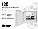
Program Switch - Used to select from the three different programs (A, B and C)
when setting program. It is also used to select which pre-set program (A, B or C) to run
for semi-automatic operation.
Function Switch - Used to stop a program’s watering cycle and any valves that are
currently running if positioned to OFF or STOP. In this mode, all programs are retained
and watering will not resume until the switch is returned to RUN or Manual. To set or
change the controller’s programs, position the Function Switch to Set Programs. Place
the switch into the Run or Manual position to operate manually or activate the controller’s
automatic watering cycles.
Semi-Auto Start Button - Used in conjunction with the Program Switch. When
depressed, it immediately starts the program selected at the Program Switch, (A, B or
C), regardless of its automatic start time.
Manual Start Button - Used
in conjunction with the Multi-
Function Dial and +/- Buttons.
When depressed, it operates the
selected valve indicated by the
Multi-Function Dial for the duration
entered by the user.
Multi-Function Dial - Used to
set, check or change program
information in conjunction with the
+/- Buttons. After using the dial,
always return it to the Current Time
position.
+/- Buttons - Used in
conjunction with Multi-Function
Dial to set or change program
information. It is usually used to
advance or decrease numbers or
toggle from ON or OFF selection.
Single finger taps to either button
will advance or reduce data one
character at a time. Holding either
button down will advance data at a
rate of 12 characters per seconds.
LCD Display - Shows the current
operation.
8
SEMI-AUTO
Start A, B, or C
OFF
or
STOP
RUN
or
Manual
MANUALSET PROGRAMS
S
T
A
R
T
T
I
M
E
S
S
C
H
E
D
U
L
E
V
A
L
V
E
R
U
N
T
I
M
E
S
CURRENT
TIME
Today
Sun
Mon
Tue
Wed
Thu
Fri
Sat
Skip Days
1
1
2
12
11
10
4
3
5
6
7
8
9
2
3
RD - 1200
Figure 5
Program Switch
LCD Display
+/- Buttons
Multi-Function
Dial
Manual Start Button
Function Switch
Semi-Auto
Start Button
Buttons and Switches Functions

“Valve Run Time”Settings - These settings control how long each valve will
water. The valve numbers on the Multi-Function Dial corresponds to the numbers on the
controller’s terminal module. The valves run sequentially one at a time. Each valve can be
set to run from 1 minute to 5.9 hours.
“Start Times” Settings - Up to three different start times (time of day) can be
selected for each program. Multiple start times are especially useful for newly seeded
lawns.
Note: If a running program overlaps to the next day, the timer will finish the current
program before continuing to the next day schedules. Programs postponed to run after
midnight will be ignored.
“Schedule” Day Settings - This setting designates the watering interval for your
program. You can choose to water at any particular day of the week (for example,
watering every monday and thursday), or use the pre-programmed Skip Days option (e.g.
water every 4 days, water every 3 days, etc.).
“Today”Settings - This setting is used to designate what day Today is. Scroll
through either MO–SU option or numerical option using the
+/- buttons, depending on
your Schedule setting.
The Rain Dial control module can be easily removed for complete programming or service
in a more convenient location. The module’s battery power will keep the program stored
until the module is re-electrified.
Step 1 - To remove the module, swing open
the control module by flexing the
release tab to the right.
Step 2 - Grasp the ribbon cable assembly
closest to the connector and pull it
out from the socket. See Figure 6.
Step 3 - Carefully unsnap the module from
the two hinge post.
Step 4 - After programming or servicing,
reinstall the control module by
reversing the steps above.
9
“Anywhere” Programming
How the Multi-Function Dial Works
Figure 6

Information Displayed When Programming
The LCD will display the following data with the Function Switch in the
SET PROGRAMS position, in conjunction with the following dial settings.
Valve Run Times - Shows minutes (e.g. 15 MIN) or hour (e.g. 1.5
HOUR). Also displays OFF for unused valves.
Start Times - Displays time in AM, PM or OFF for unused start times.
Skip Days - Shows days numbered 1–15, or OFF. The words, ONCE
EVERY appear to the left.
Schedule - Displays ON or OFF. If Skip Days has been set, three
dashes (–) and the words SKIP MODE will be displayed for each of
the seven daily settings.
Today - Displays seven individual days for a weekly schedule, or
displays day interval numbers (1–15) for a Skip Days schedule.
Information Displayed During Operation
With the Function Switch in the RUN position and the dial set to
CURRENT TIME, the currently operating valve number will be
displayed.
Automatic Mode with No Program ON - With the Function Switch
in the RUN position, the current time with a flashing colon (:) is
displayed. If the entire display is flashing, the controller has just been
plugged in or there has been a power outage. If the colon is not
flashing, the controller is using battery power.
Automatic or Semi-Auto Mode With Program ON - Displays the
current time. Turn the dial to an active valve and the display will show
the valve number, the program (A, B or C) and the time remaining for
that valve to run. If you turn the dial to a valve that is not currently on,
the display shows OFF (even though that valve may have a
programmed run time).
Manual Mode - With the dial pointing to the appropriate valve, the
display shows the valve’s number, an M (for manual), and the time
remaining for the valve to run.
Short / Malfunction Detection - A flashing OFF indicates that the
dial is pointing to a valve that has a short or other electrical
malfunction.
Note: After a power outage or when the controller is energized, the display will flash
12:00 PM (or the current time if it was a short outage). Stop the flashing by pressing
either of the +/- Buttons.
10
What the LCD Display Indicate

Plants, soil and climatological conditions vary from region to region. Consult your local
nursery for the watering schedule best suited to your particular requirements. As a general
rule, the best time to water is early morning because evaporation, wind drift and
temperature are minimal. Evening watering may promote mildew and fungus growth.
Use the chart on this page to note your valve locations, their corresponding numbers and
their auto operation.
Documenting Your Automatic Operation
Watering Considerations
PROGRAMMING WATERING SCHEDULE
WATERING TIMES
Valve
Station
A
Program
B
Program
C
Program Valve / Station Description
Start Times
1st 2nd 3rd
Watering
Days
1
2
3
4
5
6
7
8
9
10
11
12
11

12
PROGRAMMING WATERING SCHEDULE
WATERING TIMES
Valve
Station
A
Program
B
Program
C
Program Valve / Station Description
Start Times
1st 2nd 3rd
Watering
Days
1
2
3
4
5
6
7
8
9
10
11
12
Watering Schedule Chart

If the battery fails during a power interruption, your program will be lost. When power is
restored, the Rain Dial controller will automatically default to its fail-safe mode. Upon
restoration of power, the fail-safe mode will default to Sunday, 12:00 p.m. and the clock
resumes from that point. Unless reprogrammed, the controller will energize each valve for
10 minutes, beginning at 7:00 a.m. (controller clock time) everyday. This feature is
designed to protect lawns and plants from dying out when a power outage occur while
you are away from home for a prolonged period of time.
Note: In freeze prone areas, disconnect the controller while you are away to prevent
activation of the fail-safe program.
Step 1 - Set the Multi-Function Dial to CURRENT TIME.
Step 2 - Position the Function Switch to SET PROGRAMS.
Step 3 - Use the +/- Buttons to set the current time.
Step 4 - Turn the Multi-Function Dial to TODAY.
Step 5 - Use the +/- Buttons to select the current day from the MO–SU options. If using
the Skip Days option, select a numerical number to designate what day today
should be according to your planned schedule. For example, if you want to
water every 8 days and you watered 4 days ago, you would enter the number 4
in the Today setting so that in 4 more days, watering cycle will begin.
Step 6 - Return the Multi-Function Dial to the CURRENT TIME position and the
Function Switch to the RUN position when finished.
Step 1 - Set Program Switch to A.
Step 2 - Move Function Switch to SET PROGRAMS.
Step 3 - Turn the Multi-Function Dial to valve number 1.
Step 4 - Use the +/- Buttons to enter how long the valve will water during program A.
Step 5 - Repeat Sept 3 for valve number 2, valve number 3 and so on. Set unused
valves to OFF.
Repeat the above steps if you wish to use programs B and C.
Step 1 - Set Program Switch to the desired program (A, B, or C).
Step 2 - Move Function Switch to SET PROGRAMS.
Step 3 - Turn the Multi-Function Dial to the START TIMES number 1.
Step 4 - Use the +/- Buttons to enter the time when you want the program to start.
Step 5 - If you want the selected program to water more than once a day, turn dial to
START TIME number 2 and repeat step 3. To turn off a start time, press
the + button until OFF is displayed. OFF is displayed after 11:59 PM.
Fail Safe Mode
Setting the Current Time and Day
Setting Valve Run Times
Setting Program Start Times
13

Before setting the schedule, decide whether you want to use the controller’s daily
schedule option or the interval SKIP DAYS option. The daily option gives you the option
of selecting particular days to water in no particular order (for example, water every
Monday, Wednesday and Saturday).
Daily Schedule Option
Step 1 - Position the Program Switch to A.
Step 2 - Move Function Switch to SET PROGRAMS.
Step 3 - Position the Multi-Function Dial to Sun.
Step 4 - Use the +/- button to select between ON or OFF.
Step 5 - Repeat this procedure to each succeeding day of the week.
Repeat the above steps if you wish to use programs B and C.
Note: When using this schedule option, make sure that the Skip Days is set to OFF.
Skip Days Schedule Option
Step 1 - Position the Program Switch to A.
Step 2 - Move Function Switch to SET PROGRAMS.
Step 3 - Position the Multi-Function Dial to Skip Days.
Step 4 - Use the +/- button to set the desired daily interval (for example, 3 for once every
third day.
Step 5 - Turn the Multi-Function Dial to Today and use the +/- Buttons to set which
day in the cycle today should be.
Repeat the above steps if you wish to use programs B and C.
Moving the Function Switch to the RUN setting will activate the program you have just
entered.
Step 1 - Move the Function Switch to OFF
Step 2 - Move the Program Switch to the program you wish to check
Step 3 - Turn the dial to any of the parameters you want to check.
Note: With the Function Switch in the OFF position, you can check, but you can not
change the parameters in the program.
14
Setting Program Schedule
Activating the Controller
How to Check Your Program
Note: While the Function Switch is in the RUN position, the Program Switch will
have no effect. The controller will run all three programs at their designated start times
even if the Program Switch is positioned at program A, B or C.

Semi-Auto operation runs an entire program (A, B or C) whenever you want a
supplemental watering.
Step 1 - Make sure the Function Switch is in the RUN position and the Multi-Function
Dial is pointing to the CURRENT TIME position.
Step 2 - Use the Program Switch to select the program (A, B or C) you want to run.
Step 3 - Press the SEMI-AUTO Start Button to start the cycle. The controller will
resume its regular schedule when the cycle is finished.
To cancel the SEMI-AUTO operation, move the function switch to OFF or
STOP, then back to RUN or MANUAL.
Manual Operation runs a single valve for the duration you designate.
Step 1 - Make sure the Function Switch is in the RUN position.
Step 2 - Position the dial to the valve number (1–12) you want to run.
Step 3 - Use the +/- Buttons to specify the amount of time you want the valve to water.
Step 4 - Press the Manual Start Button.
Step 5 - Return the Multi-Function Dial to CURRENT TIME position. Move the Function
Switch to OFF or STOP position to cancel manual operation.
Note: If the Multi-Function Dial is left at the valve number position, the display will show
an M (for manual), the valve number, and the time remaining for that valve to run. When
the manual cycle is complete, the controller will resume its regular schedule.
Step 1 - Make sure the Multi-Function Dial points to the CURRENT TIME position.
Step 2 - Move the Function Switch to OFF.
The scheduled watering cycles will resume when the Function Switch is returned to
RUN position.
Step 1 - Disconnect the power source to the controller.
Step 2 - Carefully remove the fuse from the fuse clips.
Step 3 - Install a new 2.0 amps Slo-Blo fuse, ensuring
that it is securely seated at both ends of the
fuse clip. See Figure 6.
Step 4 - Restore power to the controller.
Semi-Auto Operation
Manual Operation
Manual Shut-Off
Fuse Replacement
Figure 6
2 Amps
Slo-Blo Fuse
WARNING:The fuse protects the transformer from overload due to a short
circuit condition. For continued protection against risk of fire, replace only
with the same type and rating of fuse. Ensure power to the controller is off
prior to removing or installing fuse.
15

The Rain Dial controllers are uniquely able to detect and identify malfunctioning valves
caused by electrical shorts in the wiring. Use your controller to check any or all valves for
shorts.
Step 1 - Make sure the Function Switch is set to RUN.
Step 2 - Turn the Multi-Function Dial to the valve number you want to check.
Step 3 - Use the +/- Button to enter a run time.
Step 4 - Press the Manual Button.
If the display flashes OFF, that particular valve has an electrical short or other problem.
The solenoid and field wiring should be inspected.
CAUTION: Do not test valves by touching wire ends to the terminal screws. Serious
damage to the controller may result.
16
How to Check for Valve Shorts
Troubleshooting the System
Problem
Some valves do not
operate.
No valves operate.
Possible Cause
Defective solenoid
Loose wire connection.
Function Switch in OFF
or STOP position.
Solenoid defective.
Loose wire connection.
Day set to OFF.
Skip Days incorrectly set.
Start Times set to OFF.
Correction
Test and replace solenoid.
Secure wire connections.
Check for connection continuity.
Set switch to RUN or MANUAL
position.
Test and replace solenoid.
Secure wire connections.
Check for connection continuity.
Check current day in display.
Set dial to correct day and
check setting.
Check and reprogram Skip
Days schedule option.
Reprogram Start Times.

17
Troubleshooting the System
Problem
Watering at wrong
times.
Blank display.
Program won’t
display.
Incorrect display (after
a power outage or after
being unplugged).
Waters on wrong
days.
Current time is wrong
and flashing.
Display is flashing.
Valve won’t turn off
(function switch off).
Possible Cause
CURRENT TIME of day
incorrectly set.
No power.
Wrong function setting.
Controller is in watering
cycle.
Battery is weak or
missing.
Weekly or Skip Days
schedule are incorrectly
set.
Power outage occurred
with no battery or weak
battery in controller.
Excessive load.
Shorted solenoid or field
wiring.
Mechanical override
(Manual bleed is on).
Correction
Check and reset CURRENT
TIME.
Check circuit breaker panel.
Check wiring connections.
Check transformer.
Check controller terminal board
fuse.
Function Switch must be in
RUN or MANUAL setting.
Check or change program with
Function Switch in Set
Programs.
Remove AC power and battery
for 1 minute. Replace battery,
restore power and reprogram.
Reprogram Program Schedule
(Page 11).
Replace battery and reprogram
controller.
Check max. ratings. (See the
bottom note on page 5.)
Check solenoids and wiring.
Turn solenoid on top of valve
fully clockwise.

18
Notes

19
Domestic: This equipment has been tested and found to comply with the limits for a Class
B digital device, pursuant to Part 15 of the FCC Rules. These limits are designed to
provide reasonable protection against harmful interference in a residential installation. This
equipment generates, uses and can radiate radio frequency energy and, if not installed
and used in accordance with the instructions, may cause harmful interference to radio
communications. However, there is no guarantee that interference will not occur in a
particular installation. If this equipment does harmful interference to radio or television
reception, which can be determined by turning the equipment off and on, the user is
encouraged to try to correct the interference by one or more of the following measures:
1. Reorient or relocate the receiving antenna.
2. Increase the separation between the equipment and receiver.
3. Connect the equipment into an outlet on a circuit different from that to which the receiver
is connected.
4. Consult the dealer or an experienced radio/TV technician for help.
The user may find the following booklet prepared by the Federal Communications
Commission helpful:
“How To Identify and Resolve Radio-TV Interference Problems”. This booklet is available
from the U.S. Government Printing Office, Washington, DC 20402. Stock No. 004-000-
00345-4.
International: This is a CISPR 22 Class B product.
FCC Notice

Irritrol Systems offers complete lines of professional
irrigation products for commercial and
residential applications:
Controller and Controller Accessories
Valves and Valve Accessories
Sprinklers, Nozzles and Sprayheads
© 2001 Irritrol Systems Form No. 373-0151 Rev. A
U.S.A.:
P.O. Box 489
Riverside, California 92502
Tel: (909) 785-3623
(800) 634-8873
Europa:
Irritrol Systems Europe s.p.a.
Via dell’Artigianato, 1/3-Loc Prato della Corta
00065 Fiano Romano (Roma), Italia
Tel: (39) 0765 455201
Australia:
Irritrol Systems PTY Ltd.
53 Howards Road
Beverley SA 5009
Tel: (08) 8300 3633
/