PDX-8 (Snare)
Adjusting the head tension
1. Finger-tighten all of the tuning bolts in
the sequence shown in the illustration.
The appropriate amount of tension is one
that will provide approximately the same
striking response as on an acoustic drum.
2. Use the drum key to adjust the tension as
needed.
4 3
2 5
6 1
CY-8 component names
CY-5 (Hi-hat)
CY-5 component names
Pad face
Bow
Edge
OUTPUT jack
Pad face
Bow
Edge
OUTPUT jack
NOTE
Continuous playing may cause dis-coloration of the pad, but this will not aect the Pad’s function.
CY-8 (Crash/Ride cymbal)
Component names
PD-8A (Tom)
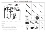
Fixing the cables (CY-8)
Secure the cable in
place with the cable tie
Leave some slack in
the cable
Be sure to make this
small plastic hook
visible from you.
Wind a cable tie around
the pipe and tighten it
in order to not to slip.
Wind a cable tie around
a cable.
Insert the small plastic hook to
a hole to secure the cable to the
cymbal arm.
Detailed explanation of each part
Anchor bolt
Arm
Control out jack
Pedal plate
NOTE
* The tips of the anchor bolts are sharp.
Handle with care.
* When using on hard-surfaced ooring, the
anchor bolts may damage the oor. Do not
attach the anchor bolts
* To adjust the travel of the pedal, loosen the
arm bolt.
FD-8 (Hi-hat control pedal)
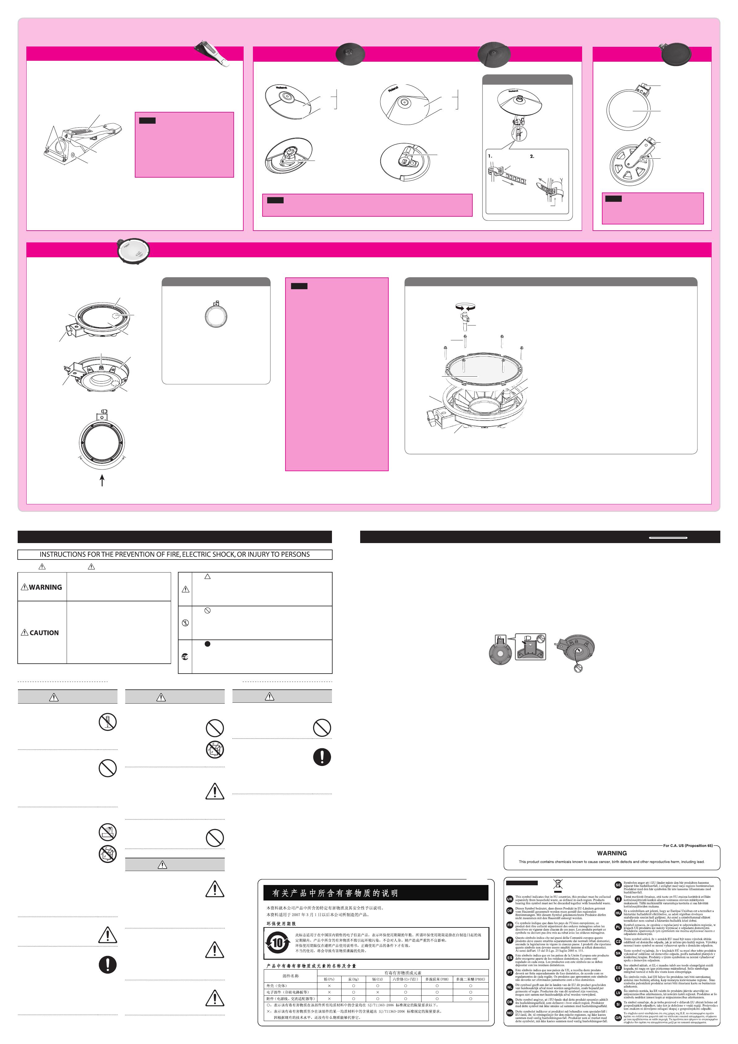
PDX-8 component names
Suitable position
for rim shots
Player
Head replacement procedure
NOTE
* Be sure to adjust the head tension of the
PDX-8 before use.
* Adjusting the head tension aects only the
head response, and does not change the pitch
of the sound as it would on an acoustic drum.
Pitch adjustments are made by editing the
sound in your drum sound module.
For details, refer to the owner’s manual of the
drum sound module you’re using.
* Striking the head when the head tension is
loose may damage the sensor and head.
* Do not apply excessive force to the sensor and
cushion located under the head. Doing so can
interfere with accurate detection, and may
damage it.
* Due to the nature of the materials used in
the sensor of the PDX-8, changes in room
temperature may aect the sensitivity of the
sensor.
* The performance of the head and/or rim
rubber will diminish with use over time.
If the head surface or the rim rubber becomes
torn, or if the head is still slack even after
you’ve adjusted its tension, or if a malfunction
occurs when you play a rim shot, please
replace the head or rim rubber.
For replacement heads or to have the rim
rubber replaced, please contact your dealer or
a Roland service center.
Wing bolt
Wing bolt
OUTPUT jack
Head
NOTE
The PD-8A is a new unit designed specically
for the TD-11K. It does not support the use of
the rim-shot technique.
WARNING
002b
Do not disassemble or modify by yourself
Do not open or perform any internal
modi cations on the unit. (The only
exception would be where this
manual provides speci c instructions
which should be followed in order to
put in place user-installable options.)
003
Do not repair or replace parts by yourself
Do not attempt to repair the unit,
or replace parts within it (except
when this manual provides speci c
instructions directing you to do so).
Refer all servicing to your retailer,
the nearest Roland Service Center, or
an authorized Roland distributor, as
listed on the “Information.”
004
Do not use or store in the following types of
locations
• Subject to temperature extremes
(e.g., direct sunlight in an enclosed
vehicle, near a heating duct, on top
of heat-generating equipment);
or are
• Damp (e.g., baths, washrooms, on
wet oors); or are
• Exposed to steam or smoke; or are
• Subject to salt exposure; or are
• Humid; or are
• Exposed to rain; or are
• Dusty or sandy; or are
• Subject to high levels of vibration
and shakiness.
005a
Use only stand (MDS series) that is recommended
This unit should be used only
with a stand (MDS series) that is
recommended by Roland.
006a
Do not place in an unstable location
When using the unit with a stand
(MDS series) recommended by
Roland, the stand must be carefully
placed so it is level and sure to
remain stable. If not using a stand,
you still need to make sure that any
location you choose for placing the
unit provides a level surface that will
properly support the unit, and keep
it from wobbling.
WARNING
011
Don’t allow foreign objects or liquids to enter unit;
never place containers with liquid on unit
Do not place containers containing
liquid on this product. Never allow
foreign objects (e.g., ammable
objects, coins, wires) or liquids
(e.g., water or juice) to enter this
product. Doing so may cause short
circuits, faulty operation, or other
malfunctions.
013
Adults must provide supervision in places where
children are present
When using the unit in locations
where children are present, be
careful so no mishandling of the
unit can take place. An adult should
always be on hand to provide
supervision and guidance.
014
Do not drop or subject to strong impact
Protect the unit from strong impact.
(Do not drop it!)
CAUTION
101c
Use only the speci ed stand (s)
This unit is designed to be used in
combination with speci c stands
(MDS series) manufactured by
Roland. If used in combination with
other stands, you risk sustaining
injuries as the result of this product
dropping down or toppling over due
to a lack of stability.
101f
Evaluate safety issues before using stands
Even if you observe the cautions
given in the owner’s manual and
setup guide, certain types of
handling may allow this product to
cause the stand to overturn.
Please be mindful of any safety issues
before using this product.
104
Manage cables for safety
Try to prevent cords and cables from
becoming entangled. Also, all cords
and cables should be placed so they
are out of the reach of children.
CAUTION
106
Avoid climbing on top of the unit, or placing heavy
objects on it
Never climb on top of, nor place
heavy objects on the unit.
118d
Keep small items out of the reach of children
To prevent accidental ingestion
of the parts listed below, always
keep them out of the reach of small
children.
• Removable Parts
nuts, washers, screws, anchor bolts,
springs
Used for instructions intended to alert the
user to the risk of injury or material
damage should the unit be used
improperly.
* Material damage refers to damage or
other adverse effects caused with
respect to the home and all its
furnishings, as well to domestic animals
or pets.
Used for instructions intended to alert the
user to the risk of death or severe injury
should the unit be used improperly.
The symbol alerts the user to things that must be
carried out. The specific thing that must be done is
indicated by the design contained within the circle. In the
case of the symbol at left, it means that the power-cord
plug must be unplugged from the outlet.
The symbol alerts the user to important instructions or
warnings.The specific meaning of the symbol is
determined by the design contained within the triangle. In
the case of the symbol at left, it is used for general
cautions, warnings, or alerts to danger.
The symbol alerts the user to items that must never be
carried out (are forbidden). The specific thing that must
not be done is indicated by the design contained within
the circle. In the case of the symbol at left, it means that
the unit must never be disassembled.
About WARNING and CAUTION Notices
About the Symbols
ALWAYS OBSERVE THE FOLLOWING
Placement
354a
• Do not expose the unit to direct sunlight, place it near
devices that radiate heat, leave it inside an enclosed vehicle,
or otherwise subject it to temperature extremes. Excessive
heat can deform or discolor the unit.
355b
• When moved from one location to another where the
temperature and/or humidity is very di erent, water
droplets (condensation) may form inside the unit. Damage
or malfunction may result if you attempt to use the unit in
this condition. Therefore, before using the unit, you must
allow it to stand for several hours, until the condensation
has completely evaporated.
356
• Do not allow rubber, vinyl, or similar materials to remain on
this unit for long periods of time. Such objects can discolor
or otherwise harmfully a ect the nish.
361
• Do not put anything that contains water on this unit. Also,
avoid the use of insecticides, perfumes, alcohol, nail polish,
spray cans, etc., near the unit. Swiftly wipe away any liquid
that spills on the unit using a dry, soft cloth.
Maintenance
401a
• For everyday cleaning wipe the unit with a soft, dry cloth or
one that has been slightly dampened with water. To remove
stubborn dirt, use a cloth impregnated with a mild, non-
abrasive detergent. Afterwards, be sure to wipe the unit
thoroughly with a soft, dry cloth.
(KD-9)
As routine maintenance, you should wipe the striking
surface using a dry, soft cloth.
402
• Never use benzine, thinners, alcohol or solvents of any kind,
to avoid the possibility of discoloration and/or deformation.
Additional Precautions
• The rubber portion of the striking surface is treated with a
preservative to maintain its performance. With the passage
of time, this preservative may appear on the surface as
a white stain, or reveal how the pads were struck during
product testing. This does not a ect the performance or
functionality of the product, and you may continue using it
with con dence.
• Continuous playing may cause dis-coloration of the pad, but
this will not a ect the Pad’s function.
• Do not insert hands or ngers into the locations indicated
with arrows in the illustrations. Otherwise, you risk getting
injured or causing damage to the product.
553
• Use a reasonable amount of care when using the unit’s
buttons, sliders, or other controls; and when using its jacks
and connectors. Rough handling can lead to malfunctions.
556
• When disconnecting all cables, grasp the connector itself—
never pull on the cable. This way you will avoid causing
shorts, or damage to the cable’s internal elements.
559a
• When you need to transport the unit, package it in the box
(including padding) that it came in, if possible. Otherwise,
you will need to use equivalent packaging materials.
926a
• When connection cables with resistors are used, the volume
level of equipment connected to the inputs (MIX IN jack)
may be low. If this happens, use connection cables that do
not contain resistors.
962a
• In the interest of product improvement, the speci cations
and/or appearance of this unit are subject to change
without prior notice.
Copyrights/Licences/Trademarks
C-01-1
• It is forbidden by law to make an audio recording, video
recording, copy or revision of a third party’s copyrighted
work (musical work, video work, broadcast, live
performance, or other work), whether in whole or in part,
and distribute, sell, lease, perform, or broadcast it without
the permission of the copyright owner.
C-01-2
• Do not use this product for purposes that could infringe
on a copyright held by a third party. We assume no
responsibility whatsoever with regard to any infringements
of third-party copyrights arising through your use of this
product.
C-03-4
• The copyright of content in this product (the sound
waveform data, style data, accompaniment patterns, phrase
data, audio loops and image data) is reserved by Roland
Corporation.
C-03-5
• Purchasers of this product are permitted to utilize said
content for the creating, performing, recording and
distributing original musical works.
C-03-6
• Purchasers of this product are NOT permitted to extract
said content in original or modi ed form, for the purpose
of distributing recorded medium of said content or making
them available on a computer network.
2a
• MMP (Moore Microprocessor Portfolio) refers to a patent
portfolio concerned with microprocessor architecture,
which was developed by Technology Properties Limited
(TPL). Roland has licensed this technology from the TPL
Group.
• MPEG Layer-3 audio compression technology is licensed
from Fraunhofer IIS Corporation and THOMSON Multimedia
Corporation.
• ASIO is a trademark of Steinberg Media Technologies GmbH.
3a
• Roland, SuperNATURAL, V-Drums, V-COMPACT are either
registered trademarks or trademarks of Roland Corporation
in the United States and/or other countries.
T-01
• Company names and product names appearing in this
document are registered trademarks or trademarks of their
respective owners.
For EU Countries
For China
IMPORTANT NOTESUSING THE UNIT SAFELY
Component names
1. Remove all tuning bolts and washers.
* Do not apply excessive force to the sensor and
cushion located under the head. Doing so can
interfere with accurate detection, and may damage
it.
2. Remove the old head.
3. Place the new head on the shell.
4. Attach the tuning bolts to the head and shell.
5. Adjust the head tension.
For details, refer to the explanation on “Adjust-
ing the head tension”.
Loosen Tighten
Tuning bolts
Head
Rim rubber
Shell
Head sensor
Rim sensor
Drum key
Wing nut
Head
Tuning bolts
OUTPUT jack
Rim rubber
Head
sensor
Shell
Rim sensor
Holder