Page is loading ...

user manual
Cyclo Directional IP65

150
230
135
93
121
230
Height
incl.
mounting
bracket
242
1257
Dimensions
Measurements are in millimeters
©2007 Martin Professional A/S, Denmark. All rights reserved. No part of this manual may be
reproduced, in any form or by any means, without permission in writing from Martin Professional
A/S, Denmark. Information subject to change without notice. Martin Professional A/S and all
affiliated companies disclaim liability for any injury, damage, direct or indirect loss,
consequential or economic loss or any other loss occasioned by the use of, inability to use or
reliance on the information contained in this manual.
P/N 35000191, Rev. A

Safety information 3
Safety information
The following symbols are used to identify important safety information:
DANGER! This product is not for household use. It presents risks of
injury due to electric shock, fire, burns and falls if safety precautions
are not followed.
Read this manual before installing, powering, operating or servicing
the luminaire. Follow the safety precautions listed below, and observe
all warnings in this manual and on the luminaire. Use the luminaire
only as described in this manual and in accordance with local laws
and regulations. Refer any operation not described in this manual to a
qualified technician.
If you have any questions about how to operate this luminaire safely, contact
your Martin Architectural supplier or call the Martin 24-hour service hotline
on +45 70 200 201.
Protection from electric shock
• Do not use the luminaire if any cable, seal, cover, housing or other
component is cracked, deformed or damaged in any way.
• Isolate the luminaire from power and lock out power before removing or
installing a tube, fuses or any part
WARNING!
Read the safety precautions in this
section before installing, powering,
operating or servicing this product.
Danger! Safety
hazard. Risk of
personal injury or
death.
Danger! Hazardous
voltage. Contact
will cause electric
shock.
Danger! Fire
hazard.
Warning! Burn
hazard. Hot
surface. Do not
touch.

4 Cyclo IP65 Directional user manual
• Always ground (earth) the luminaire electrically.
• Use only a source of AC power that complies with local building and
electrical codes and has both overload and ground (earth) fault protection.
• Ensure that the AC power distribution system includes a means of
isolating all installed devices from power and locking out power during
service.
• Ensure that all components in the AC power distribution circuits (cables,
junction boxes, etc.) are protected from water and airborne particles to
IP67 or higher, are suitably dimensioned for the current and power
requirements of the devices installed, and are of suitable type for the
location (including water, pollution, temperature and UV resistance).
• Do not expose the luminaire to a high-pressure water jet.
• Do not immerse the luminaire in water or install it in a location where
flooding may occur.
• Refer all service not described in this manual to a Martin service
technician.
Protection from burns and fire
• Do not operate the luminaire if the ambient temperature (T
a
) exceeds 40°
C (104° F).
• Keep flammable materials well away from the luminaire.
• Allow the luminaire to cool for 15 minutes before servicing.
• Do not attempt to bypass thermostatic switches or fuses. Replace
defective fuses with ones of the specified type and rating only.
• Do not modify the luminaire. Install only genuine Martin parts and
approved fluorescent tubes of the type and wattage specified for the
armature.
• Provide a minimum clearance of 25 mm (1 inch) and unobstructed airflow
around the luminaire.
• Do not mask or modify light output with filters or other materials.
Protection from injury due to falls
• Block access below the work area and work from a stable platform
whenever installing, servicing or removing the luminaire.
• Ensure that all supporting structures, surfaces, fasteners and lifting
equipment can bear the weight of all the devices they are intended to
support plus an adequate safety margin, and that they conform to local
building and safety regulations.
• Use fasteners that have sufficient corrosion resistance, dimensions and
strength to mount the luminaire safely. Any nuts used must be self-
locking.
• Ensure that all components and installation fittings are securely fastened.

Contents
Safety information . . . . . . . . . . . . . . . . . . . . . . . . . . . . . . . . . . . . . 3
Product overview. . . . . . . . . . . . . . . . . . . . . . . . . . . . . . . . . . . . . . . 6
Introduction . . . . . . . . . . . . . . . . . . . . . . . . . . . . . . . . . . . . . . . . . . . . 7
Installation . . . . . . . . . . . . . . . . . . . . . . . . . . . . . . . . . . . . . . . . . . . . . 8
Included items. . . . . . . . . . . . . . . . . . . . . . . . . . . . . . . . . . . . . . . . . . . 8
Access to tube module . . . . . . . . . . . . . . . . . . . . . . . . . . . . . . . . . . . . 9
Access to connections compartment . . . . . . . . . . . . . . . . . . . . . . . . 10
Mounting . . . . . . . . . . . . . . . . . . . . . . . . . . . . . . . . . . . . . . . . . . . . . . 11
Orientation and adjustment. . . . . . . . . . . . . . . . . . . . . . . . . . . . . . . . 12
Cable entry . . . . . . . . . . . . . . . . . . . . . . . . . . . . . . . . . . . . . . . . . . . . 15
AC power . . . . . . . . . . . . . . . . . . . . . . . . . . . . . . . . . . . . . . . . . . . . . 18
Linking luminaires for DMX and synchronized operation . . . . . . . . . 21
Operation: general . . . . . . . . . . . . . . . . . . . . . . . . . . . . . . . . . . . . 27
Fluorescent tube lifetimes and performance. . . . . . . . . . . . . . . . . . . 27
Avoiding condensation and humidity. . . . . . . . . . . . . . . . . . . . . . . . . 27
Operation in extreme ambient temperatures. . . . . . . . . . . . . . . . . . . 28
Stand-alone operation. . . . . . . . . . . . . . . . . . . . . . . . . . . . . . . . . 29
Stand-alone operation settings . . . . . . . . . . . . . . . . . . . . . . . . . . . . . 30
Single stand-alone operation . . . . . . . . . . . . . . . . . . . . . . . . . . . . . . 31
Master/slave stand-alone operation . . . . . . . . . . . . . . . . . . . . . . . . . 31
DMX-controlled operation. . . . . . . . . . . . . . . . . . . . . . . . . . . . . 35
DMX control functions. . . . . . . . . . . . . . . . . . . . . . . . . . . . . . . . . . . . 35
Service . . . . . . . . . . . . . . . . . . . . . . . . . . . . . . . . . . . . . . . . . . . . . . . . 36
Cleaning . . . . . . . . . . . . . . . . . . . . . . . . . . . . . . . . . . . . . . . . . . . . . . 36
Tube replacement. . . . . . . . . . . . . . . . . . . . . . . . . . . . . . . . . . . . . . . 36
Main fuse replacement . . . . . . . . . . . . . . . . . . . . . . . . . . . . . . . . . . . 39
Voltage setting . . . . . . . . . . . . . . . . . . . . . . . . . . . . . . . . . . . . . . . . . 40
Troubleshooting . . . . . . . . . . . . . . . . . . . . . . . . . . . . . . . . . . . . . . . 41
DMX protocols. . . . . . . . . . . . . . . . . . . . . . . . . . . . . . . . . . . . . . . . 42
Cyclo IP65 Directional specifications . . . . . . . . . . . . . . . . . 43

6 Cyclo IP65 Directional user manual
A
B
D
C
Product overview
A – Tube module
B – Base module
C – Front cover
D – Metal cable glands (if used)

Introduction 7
Introduction
Thank you for selecting a luminaire from the Martin Architectural
®
Cyclo
IP65 Directional series. Cyclo IP65 Directional luminaires are fluorescent
tube-based dynamic color-changing luminaires designed for illumination of
walls and surfaces. Dimmable 54 watt T5 fluorescent tubes combine high
efficiency, bright color and long lamp life. Luminaires are designed for
surface mounting, and adjustable arms allow tilting through a wide range of
angles.
Cyclo IP65 Directional luminaires offer independent 0-100% control of tube
intensity using a standard DMX controller. They can also be programmed to
run stand-alone light shows alone or in synchronized groups.
Two models are available. The 03 has red, green and blue tubes, allowing
RGB additive color mixing. The 04 has red, green and blue tubes plus a cool
daylight white tube, allowing RGBW color mixing. The color temperature of
the white tube’s output can be controlled using the colored tubes.
Luminaires are dustproof and protected from water projections and low-
pressure water jets to IP65. A self-purging humidity valve eliminates
condensation. Luminaires can start and operate with tubes dimmed to 1%
light output in ambient temperatures as low as -20° C (-4° F).
Versions are available to suit the following voltage ranges:
• 120 V models accept 100-130 V nominal AC power at 50/60 Hz.
• 230 V models accept 200-240 V nominal AC power at 50/60 Hz.
Martin Architectural can offer expert assistance with planning an installation,
if desired.
Installation, on-site service and maintenance can be provided worldwide by
the Martin
®
Global Service organization and its authorized agents.
Choosing a Martin service contract gives owners access to Martin’s
expertise and product knowledge in a partnership that will ensure the
highest level of performance throughout the product’s lifetime.
The most recent version of this user manual is available from the Support
area of http://www.martin-architectural.com

8 Cyclo IP65 Directional user manual
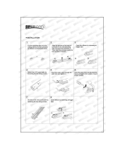
Installation
DANGER! Read “Safety information” on page 3 before attempting to
install this product.
The safety and suitability of lifting equipment, installation location,
anchoring method, mounting hardware and electrical circuits are the
responsibility of the installer. All local safety regulations and legal
requirements must be observed when installing and connecting the
Cyclo IP65 Directional. Installation must be carried out by qualified
professionals only.
This section describes how to install the luminaire, including how to connect
it to power and control data cables, and how to set it up for DMX control or
stand-alone operation.
We recommend that you read the Installation section of this manual and
familiarize yourself with the procedures involved before starting to install
luminaires. If you are not familiar with DMX, pay particular attention to the
section on setting DMX addresses.
Included items
Cyclo IP65 Directional luminaires are supplied with the following items:
• Osram T5 fluorescent tubes (installed)
• Surface-mounting bracket.
• Two TET 5-7 Thorsman rubber membrane cable glands (installed) for
data cable entry: cable diameter 5-7 mm (0.20-0.28 in.)
• Two TET 10-14 Thorsman rubber membrane cable glands (installed) for
power cable entry: cable diameter 10-14 mm (0.40-0.55 in.)
• Two M25 metal blanking plugs (installed) for unused power cable entry
holes.
• Two M16 metal blanking plugs (installed) for unused data cable entry
holes.
• Two M25 metal IP68 cable glands (supplied loose) for AC power cable
entry: cable diameter 7 - 15 mm (0.28 - 0.6 in.).
• Two M16 metal IP68 cable glands (supplied loose) for data cable entry:
cable diameter 5 - 12 mm (0.2 - 0.45 in.).

Installation 9
Access to tube module
Various operations described in this manual require access to the inside of
the module that contains the tubes. To access the inside of the tube module:
1. Isolate the luminaire from power and ensure that power cannot be
reconnected.
2. See Figure 1. Loosen the three front cover release screws in the hinged
front cover release flap until they turn freely.
3. See Figure 2. Lift
the release flap (A)
and then lift the
hinged front cover
(B). If you need to
lever the release
flap up, use a
plastic or wooden
object, as a metal
object may
damage the glass.
Avoid damaging
seals while you are
working.
4. To close the front
cover, first close
the cover (B), then
close the release
flap (A) so that it clips down over the cover. The seals on the inside faces
of covers must be in perfect condition to maintain their waterproof
qualities. Avoid damaging them. Any seal that is not in perfect condition
must be replaced by a Martin service agent.
.
Figure 1: Front cover release screws
A
B
Figure 2: Opening the front cover

10 Cyclo IP65 Directional user manual
Access to connections compartment
Various operations described in the is manual require access to the
connections compartment in the base module. To access the connections
compartment:
1. See Figure 3. Remove the two screws from the ends of the connections
compartment cover.
2. Open the hinged release flap (A) and then open the hinged cover (B).
Avoid damaging the seal on the inside of the cover.
3. To close the connections compartment, first close the hinged cover (B),
then close the release flap (A) so that it clips down over the cover. The
seals on the inside faces of covers must be in perfect condition to
maintain their waterproof qualities. Avoid damaging them. Any seal that
is not in perfect condition must be replaced by a Martin service agent.
4. Tighten the two screws at either end of the cover before applying power.
A
B
Figure 3: Opening the connections compartment cover

Installation 11
Mounting
DANGER! It is the installer’s responsibility to ensure that the
installation is safe and that all local safety regulations and legal
requirements are observed when mounting the Cyclo IP65 Directional.
The Cyclo IP65 Directional can be surface-mounted on a floor, wall or
ceiling. To surface-mount the Cyclo IP65 Directional:
1. Ensure that the mounting surface is flat and can support the weight of all
the devices to be installed on it. Allow 25 mm (1 inch) of free space
around each luminaire.
2. Using the mounting bracket as a guide, mark up and drill holes in the
mounting surface to take mounting fasteners.
3. Fasten the mounting bracket to the surface with at least two fasteners
that have sufficient corrosion resistance and strength to mount the
luminaire safely. Choice of mounting hardware will depend on the
installation, but use high-quality corrosion-resistant fasteners with
recommended minimum properties grade A4-70 (ISO 3506), or grade 8.8
(ISO 898-1). Any nuts used must be self-locking.
4. Check that the bracket is not distorted and is securely attached to the
mounting surface.
5. See Figure 4. To install the luminaire on the mounting bracket, hook the
raised T-section (A) on the lower side of the luminaire base into the
channel (B) on the mounting bracket, then swing the luminaire up so that
1
A B
5mm
2
C E D
Figure 4: Installing on the mounting bracket

12 Cyclo IP65 Directional user manual
the T-section (C) on the upper side of the base passes behind the
retaining rail (D).
6. Tighten the retaining screws (E) so that the retaining rail (D) grips the T-
section (C) tightly. Check that the luminaire is held securely.
Orientation and adjustment
Important! The Cyclo IP65 Directional support arms must both
be fixed at the same angle. Do not twist the luminaire in the
support arms, or you may deform the product and make it
impossible to obtain a waterproof seal.
The Cyclo IP65 Directional can be installed in any orientation.
See Figure 5. The angle of the support arms can be adjusted in the base
module, and the tube module can be rotated in the support arms, allowing a
wide range of tilt angles.
90°
0°
15°
30°
45°
15°
30°
45°
120°
0°
60°
= 60°
= 60°
60°
45°
= 105°
= 105°
Figure 5: Tilt angle adjustment

Installation 13
Adjusting the support arm angle
To adjust the angle of the support arms in the base module:
1. Ensure that the luminaire is securely mounted and isolated from power.
2. Open the connections compartment as described in “Access to
connections compartment” on page 10.
3. See Figure 6. Support the weight of the tube module. Loosen the arm
adjustment screws at both ends of the base module with a long Allen key,
tilt the arms to the desired angle and retighten slowly, rocking the tube
module up and down slightly while you tighten so that the adjustment
screws engage correctly in the cutouts in the arm.
4. Reinstall the connections compartment cover as described in “Access to
connections compartment” on page 10.
3mm
Figure 6: Arm-to-base adjustment screws

14 Cyclo IP65 Directional user manual
Adjusting the tube module tilt angle
To rotate the tube module in the support arms:
1. Ensure that the luminaire is securely mounted and isolated from power.
1. Open the front cover as described in “Access to tube module” on page 9.
2. See Figure 7. Loosen both the tilt adjustment screws with a long Allen
key, rotate the tube module to the desired angle, and retighten.
3. Reinstall the front cover as described in “Access to tube module” on page
9.
3mm
3mm
Figure 7: Tube module tilt adjustment screws

Installation 15
Cable entry
Two types of seal can be
used for cable entry:
Thorsman rubber
membrane cable glands
(see Figure 9) installed in
the base module and
metal cable glands (see
Figure 10) packed loose
with the product. If the
metal glands are used,
blanking plugs must be
removed and replaced
with metal glands.
Use the larger glands for
power cable entry and the
smaller glands for DMX
data cable entry.
Cable glands may need to
be replaced in the
following situations:
• If power or data cable is
used that is not within the diameters specified under “Included items” on
page 8, new cable glands that match cable diameter must be obtained
from Martin or an electrical supplier.
• Rubber and metal glands must be replaced with new items if cable in an
existing installation is replaced with cable of a different diameter.
• Used rubber membrane glands must be replaced with new unpierced
items or replaced with blanking plugs if they are no longer used for cable
entry.
• If metal cable glands are installed, they must be replaced with blanking
plugs if no longer used for cable entry.
Replacement rubber membrane glands must have the following
characteristics:
Temperature range . . . . . . . . . . . . . . . . . . . . -20° to +70°C or better
Ingress protection rating. . . . . . . . . . . . . . . . . . . . . . . . IP67 or IP68
Installation plate thickness . . . . . . . . . . . . 0.5-4.0 mm (0.02-0.17 in.)
Power cable gland installation hole diameter . . . . . .23 mm (0.91 in.)
Data cable gland installation hole diameter . . . . . . .16 mm (0.63 in.)
Figure 8: Cable gland options

16 Cyclo IP65 Directional user manual
Replacement metal glands must have the following characteristics:
Temperature range: . . . . . . . . . . . . . . . . . . . -20° to +70°C or better
Ingress protection rating: . . . . . . . . . . . . . . . . . . . . . . . IP67 or IP68
Power cable gland thread size: . . . . . . . . . . . . . . . . . . . . . . . . . M25
Data cable gland thread size: . . . . . . . . . . . . . . . . . . . . . . . . . . M16
Minimum entry thread length: . . . . . . . . . . . . . . . . . 10 mm (0.4 in.)
Installing cable using rubber membrane glands
DANGER! Using a rubber membrane
gland involves making a hole in the
membrane. A used gland is therefore
only waterproof with cable installed. If
the cable is removed, the hole in the
housing must be sealed with a
blanking plug or new gland.
To install cable using a rubber gland:
1. Push a round spiked object through
the center of the membrane from the
outside of the housing just enough to pierce it. Do not enlarge the hole or
remove rubber from the membrane.
2. Push cable through the gland from the outside of the housing.
Installing cable using metal cable glands
Two sizes of metal cable gland are supplied loose with the product. Use the
larger glands for power cable entry and the smaller glands for DMX data
cable entry.
To install cable using a metal cable gland:
1. Remove a blanking plug that matches the cable gland size from the base
module housing.
Figure 9: Thorsman rubber
membrane cable glands

Installation 17
2. See Figure 10. Dismantle the cable gland.
3. Ensure that there is a rubber O-ring A on the housing end of the cable
entry B, and screw this end into the threaded hole in the housing. Tighten
until the O-ring A makes a water-resistant seal against the outer surface
of the housing. Do not over-tighten, as this may damage the seal or
housing.
4. Thread the cable through the compression nut E, washer D, gland C, and
cable entry B into the housing.
5. Allow approx. 20 cm (8 in.) of cable slack inside the housing. Prevent the
cable entry from turning and tighten the compression nut sufficiently to
make a water-resistant seal. Do not over-tighten, as this may damage the
gland. Check that the cable is firmly gripped in the rubber gland.
Figure 10: Metal cable gland
A
B
C
D
E
A – O-ring seal
B – Cable entry
C – Gland
D – Washer
E – Compression nut

18 Cyclo IP65 Directional user manual
AC power
DANGER! It is the installer’s responsibility to ensure that all power
cable and equipment is adequately dimensioned and of appropriate
type for the installation, and that all local safety regulations and legal
requirements are observed when installing and connecting the Cyclo
IP65 Directional.
Current and power data are given in the Specifications section on page 43.
Inrush currents and electronic circuit-breakers
When fluorescent tubes with ECG (electronic control gear) systems are
switched on at the AC wave peak, a larger current surge occurs than with
conventional ballasts. If a large number of luminaires are switched on
simultaneously, this inrush current can trip electronic circuit breakers. To
avoid this in large installations, either switch on luminaires at intervals or
limit the number of luminaires per 16 A electronic circuit breaker to
approximately ten luminaires.
RCDs and common neutral conductors
Many fixed installations use common neutral conductors in branch circuit
distribution boxes. To avoid unintentional tripping of the RCD (residual
current device, or ground fault/earth leakage circuit breaker), ensure that
each luminaire’s neutral conductor is connected to AC power via the same
RCD as the live conductor.
Leakage to ground and RCDs
Each ECG “leaks” a total current of maximum 0.5 mA to ground (earth).
Luminaires must be correctly connected to ground so that this “leakage”
current can be absorbed.
Allow for the “leakage” current from ECGs when connecting luminaires to a
circuit that has an RCD for ground fault protection, otherwise the RCD may
trip unintentionally. Bear in mind that RCDs are rated at their maximum trip
current, and that some RCDs rated 30 mA may trip when leakage to ground
is as low as 20 mA.
RCDs can also be tripped by the inrush current when tubes are switched on.
To avoid unintentional tripping of RCDs:
1. Distribute power using 3 phases and install 3-phase RCDs.
2. If it is both safe and legal, use RCDs with a trip current rating higher than
30 mA. When considering this option, the installer must ensure that all
local building and electrical regulations are respected. Maximum legally

Installation 19
permitted RCD trip current ratings are normally stated in national
electrical and building codes.
3. Install surge current-resistant RCDs.
Connecting to power
A screw clamp is provided for connecting the luminaire to the power cable’s
earth conductor, and a block of spring-loaded clamp terminals are provided
for connecting the luminaire to the power cable’s live and neutral power
conductors.Some common color-coding systems for power wiring are given
below:
To connect to AC power:
1. Ensure that power cannot be applied to the cable during installation.
2. Open the connections compartment as described in “Access to
connections compartment” on page 10.
3. Pass the power input cable through a cable gland as described in “Cable
entry” on page 15 so that approximately 20 cm (8 in.) of cable is free
inside the luminaire, and prepare the end of the cable for connection.
4. See Figure 11. Four spring-loaded terminals marked L1, L2, L3 and N
and one screw clamp marked are provided for power cable
connection. The terminals marked L2 and L3 are not used to supply
power to the luminaire and are provided only to allow phase conductors
to be connected if power is supplied from a 3-phase system (see
“Connecting to a 3-phase system” on page 20).
Wire (EU) Wire (US) Pin Marking on luminaire
brown black live L1
blue white neutral N
yellow/green green ground
Table 1: Power cable color-coding systems

20 Cyclo IP65 Directional user manual
5. Connect the
conductors in the
power input cable as
follows:
• Connect the
ground (earth) wire
to the screw
terminal marked
close to the
power terminals.
• Connect the
neutral wire to the
spring-loaded
power terminal
marked N
• Connect the live
wire to the spring-
loaded power
terminal marked
L1.
6. If power is to continue to another luminaire, pass power output cable
through a cable gland as described in “Cable entry” on page 15 and
prepare the end of the cable for connection. Each spring-loaded terminal
has two holes. One hole now contains a conductor from the input cable
and one is available for a conductor from the output cable. Using the
spare holes, connect the conductors in the power output cable as
described under point 5. above.
Connecting to a 3-phase system
If you are supplying luminaires with power from a 3-phase system, the live
conductor in the power input cable that you connect to terminal L1 will be
one of the phases. Connect one of the remaining phases to terminal L2 and
the last remaining phase to terminal L3.
To distribute the load evenly over the 3 phases, connect phase 1 to terminal
L1 on one-third of the luminaires in the installation, phase 2 to terminal L1
on one-third of the luminaires, and phase 3 to terminal L1 on the remaining
one-third of the luminaires. Terminals L2 and L3 do not supply power to the
luminaire and are provided simply to allow phase conductors in separate
lengths of power cable to be joined.
To avoid confusion, each time you install a power output cable to take power
to the next luminaire, connect each phase conductor in the power output
cable to the terminal used for that phase conductor in the power input cable.
N
N
L1
L1
L2
L2
L3
L3
Shield
Shield
Figure 11: Power and DMX connections
DMX terminalsPower terminals
/