01
Drum sound module/Pads/Others
02
Stand
03 04
Connection procedure
05
Setup Guide
© 2018 Roland Corporation
Before using this unit, carefully read “USING THE UNIT SAFELY” and “IMPORTANT NOTES” (the leaet “USING THE UNIT SAFELY,” “TD-1 Owner’s Manual,” and the Setup Guide). After reading, keep the document(s)
where it will be available for immediate reference.
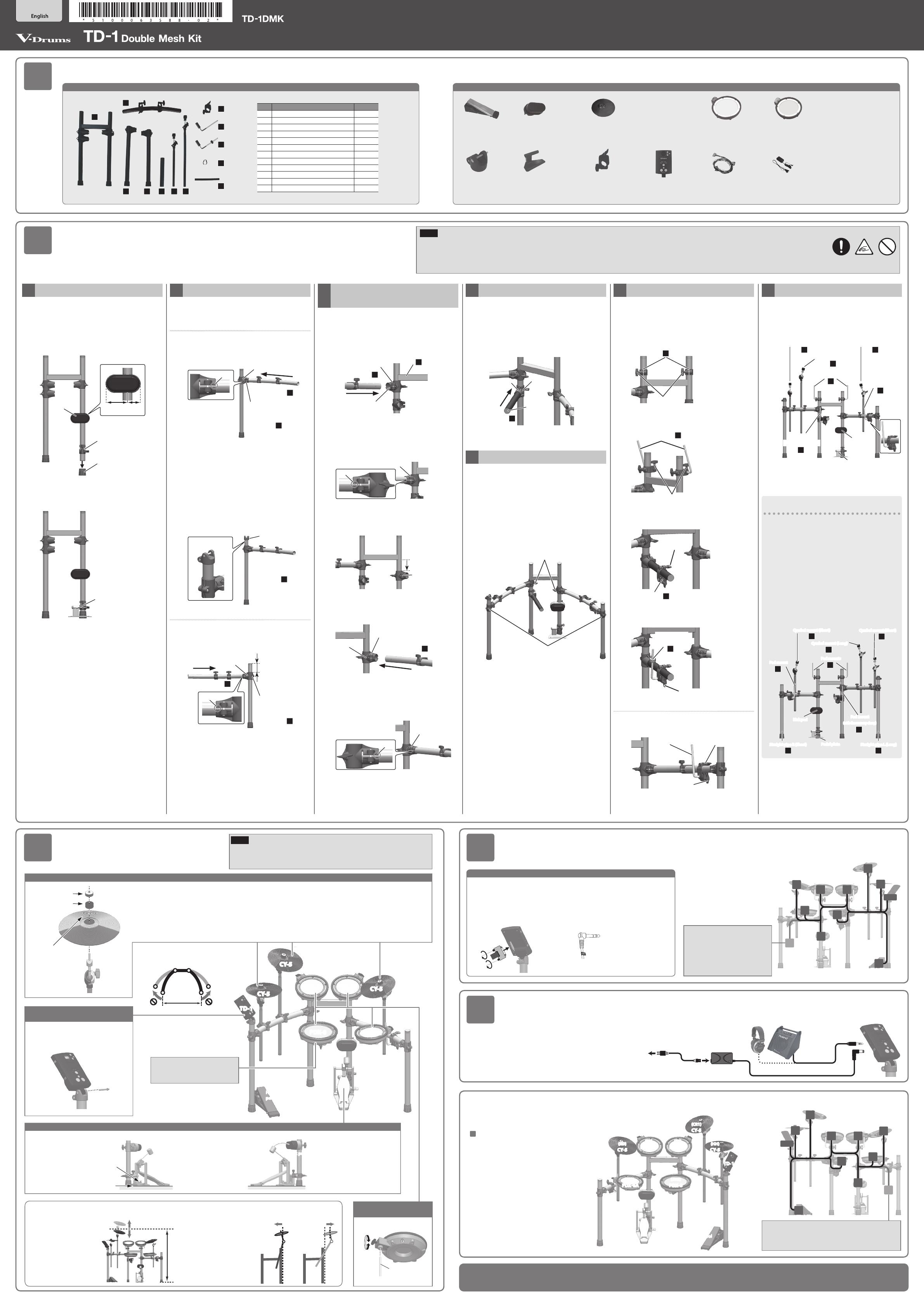
Check the included items
As soon as you open the package, check to see that all items are included. If anything is missing, please contact your dealer.
* This package does not include a kick pedal. Use with a commercially available kick pedal.
Assemble the drum stand
* If you will be using this drum stand for an extended period of time in the same location, we recommend that you use a
drum mat (TDM series) made by Roland to prevent the rubber feet from soiling the surface on which they are placed.
Attach the parts
* Do not spread the stand wider than
1.2 meters (48 inches).
Connect the pads to the drum sound module (TD-1)
* Insert the plug rmly,
making sure it’s all the
way in.
1. Connect the cable to TD-1 as
shown in the illustration.
Insert the connector all the way,
then turn the knobs to fasten it
securely.
2. Labels indicating the pad to be
connected are attached to the
cable. Connect the cable to the
OUTPUT jack of each pad as shown
in the illustration.
Connect the AC adaptor and speakers
Connect the AC adaptor, speakers, or headphones as described in
the TD-1 Owner’s Manual.
* To prevent malfunction and equipment failure,
always turn down the volume, and turn o all the
units before making any connections.
For a left-handed setup
Assemble the drum stand as described
in “For a left-handed setup” of section
“
02
Assembe the drum stand”; then
attach the parts and connect the cables
as shown in the illustration at right.
9 When you’ve nished making connections, turn on the power as described in
the TD-1 Owner’s Manual, and verify that you can hear sound.
This completes assembly and connections.
CY-5
CY-5
PDX-6A PDX-6A
CY-5
TD-1
PDX-8
PDX-6A
Hi-hat control
pedal
8 Hi-hat control
pedal
8 Cymbal pad for hi-hat/crash/ride
(CY-5 x 3)
8 Connection
cable
8 AC adaptor
8 V-Pad for tom
(PDX-6A x 3)
8 Setup Guide (this document)
8 Owner’s manual set
8 Drum key
8 Kick pad 8 V-Pad for snare
(PDX-8)
8 Drum sound
module (TD-1)
1.
Attaching the parts for the kick
1–1. Remove the cap that is attached to the stand’s
right pipe (with one holder).
1–2. Insert the kick pad and mount holder (for the
pedal plate), and provisionally fasten them in
the orientation shown in the illustration.
Kick pad
Mount holder
(for the pedal plate)
Cap
Wide Narrow
1–3. Replace the cap.
1–4. Attach the pedal plate to the mount holder.
Pedal plate
2.
Assembling the left and right arm sections
Lay the left and right arm sections on the oor while
assembling them.
Left arm section
2–1. Using a drum key, loosen the bolt on the
holder of straight pipe “L” (long), then insert
curved pipe.
Curved pipe
2
Straight pipe L
(Long)
3
Holder
Bolt
Guide hole
As a general rule, insert curved pipe until the
guide hole on the pipe can be seen through the
gap in the holder.
After rmly inserting it all the way, use the
drum key to rmly tighten bolt.
2–2. Use the drum key to loosen the bolt of the
drum sound module holder, then attach the
drum sound module holder to straight pipe
“L” (long) and tighten the bolt.
Straight pipe L
(Long)
3
Bolt
Drum sound module
holder
Right arm section
2–3. Using a drum key, loosen the bolt on the
holder of straight pipe “R” (short) then insert
curved pipe.
Curved pipe
2
Straight pipe R
(Short)
4
7 cm
Holder
Bolt
Guide hole
As a general rule, insert curved pipe until the
guide hole on the pipe can be seen through the
gap in the holder.
After rmly inserting it all the way, use the
drum key to rmly tighten bolt.
2–4. Position straight pipe “R” (short) so that its tip
protrudes by about 7 cm (3 inches), and then
tighten the holder.
3.
Attach the left and right arm sections to
the main unit
3–1. Use a drum key to loosen bolt of the holder
“A” (attached to the left-side pipe (with two
holders) of the stand), and insert left arm
(of the assembly you created in step 2) into
holder “A” of the stand.
Holder A
Bolt
Curved pipe
2
Stand
1
Left arm
As a general rule, insert curved pipe until the
guide hole on the pipe can be seen through the
gap in the holder.
After rmly inserting it all the way, use the
drum key to rmly tighten bolt.
Bolt
Guide hole
3–2. Lower the holder “B” attached to the stand’s
right pipe, moving it down to the position
shown in the illustration.
Holder B
7 cm
3–3. Use the drum key to loosen bolt of the holder
“B,” and insert right arm (of the assembly you
created in step 2) into holder “B” of the stand.
Holder B
Bolt
Curved pipe
2
Right arm
As a general rule, insert curved pipe until the
guide hole on the pipe can be seen through the
gap in the holder.
After rmly inserting it all the way, use the
drum key to rmly tighten bolt.
Bolt
Guide hole
4.
Attaching the snare pipe
4–1. Use the drum key to loosen bolt of the holder
“C,” and insert the snare pipe into holder “C”
of the stand. After rmly inserting it all the
way, use the drum key to rmly tighten bolt.
Insert the end of the snare pipe that doesn’t
have a cap on it into holder “C.”
Snare pipe
5
Holder C
Cap
Bolt
5.
Adjusting the vertical pipes
5–1. Place the stand upright, then loosen the hand
knobs of holders “A” and “B” (two places).
Next, spread open the pipes at left and right.
5–2. Verify that the four vertical pipes are truly
vertical.
If the stand wobbles, loosen the bolts on the
holders of straight pipes “L” (long) and “R” (short)
and adjust the height. After adjusting the
height, tighten the bolts on the holders.
Hand knobs
Hand knobs
6.
Attaching the pad mounts
The tips of the mounts are sharp. Handle them with
care.
6–1. Attach mount holders to the top of the stand
and tighten the respective hand knobs.
Mount holders
6
Hand knobs
6–2. Attach the pad mounts to mount holder, and
rmly tighten the respective hand knobs.
Pad mounts
7
Hand knobs
6–3. Attach mount holder to the snare pipe, and
tighten the hand knob.
Mount holder
6
Hand knob
6–4. Attach pad mount (with memory clamp) to
the snare pipe, and tighten the hand knob.
(with the memory clamp)
8
Hand knob
Pad mount
Right arm
6–5. Attach pad mount to the snare pipe, and
tighten the hand knob.
Mount holder
Hand knob
Pad mount
7.
Attaching the cymbal mounts
7–1. Insert the two cymbal mounts and the hi-hat
mount into the holders of the curved pipes,
and adjust all the holders as shown in the
illustration to complete setup.
9
Cymbal mount (Short)
9
Cymbal mount (Short)
10
Cymbal mount (Long)
7
Pad mounts
8
Pad mount
7
Pad mount
Kick pad
Pedal plate
(with memory
clamp)
For a left-handed setup
If you want to use a left-handed setup, assemble the
stand as follows.
5 Reattach the holders attached to the stand’s pipes so that
there are two holders on the right and one on the left.
5 Attach the kick pedal and the pedal plate to the left side
of the stand.
5 Assemble the left and right arm sections so that straight
pipe “R” (short) is at the left and straight pipe “L” (long)
and the drum sound module holder are at the right, and
attach them to the stand.
5 Attach the snare pipe to the right side of the stand.
5 Attach the pad mounts and cymbal mounts as shown in
the illustration.
9
Cymbal mount (Short)
9
Cymbal mount (Short)
10
Cymbal mount (Long)
7
Pad mounts
Kick pad
Pedal plate
4
Straight pipe R (Short)
7
Pad mount
3
Straight pipe L (Long)
8
Pad mount
(with the memory clamp)
NOTE
5 When setting-up or adjusting the stand, take care not to pinch your ngers between movable parts and the main unit. If using this in a location where children are present, be sure
to provide adult supervision or guidance.
5 Prepare an area in which you can perform the assembly safely.
5 Do not use a power tool (e.g., an electric screwdriver) to assemble the stand. You risk damaging or stripping the screws.
No. Name Quantity
1 Stand 1
2 Curved pipe 2
3 Straight pipe L (Long) 1
4 Straight pipe R (Short) 1
5 Snare pipe 1
6 Mount holder 3
7 Pad mount 3
8 Pad mount (with the memory clamp) 1
9 Cymbal mount (Short) 2
10 Cymbal mount (Long) 1
11 Cable clip 4
12 Cable tie 2
Adjust the rod height so
that no part of any cymbal
is higher than 1.2 meters
(48 inches) above the oor.
Attach the cymbals in
such a way that the
center of the cymbal
does not extend beyond
the rear pipes of the
stand.
Adjusting the position of the cymbal
Attach the kick pedal
1. Mount the kick pedal to the
pedal plate.
2. Adjust the position of
the kick pad and the kick
pedal so that the beater
strikes the center of the
kick pad when you step
on the kick pedal.
3. Once the kick pad and kick
pedal are in the desired
playing position, tighten
the hand knobs.
Verify that the plate and pedal rmly
contact the oor without any gap
Install the kick pedal
securely.
1.2 m
* Fasten the cables so that they will
not obstruct your playing; use
cable clips and cable ties.
Make sure to wrap the cable ties
around the pipes.
Beater
Kick pad
8 Drum sound
module holder
8 Pedal plate 8 Mount holder
(for the pedal plate)
Attach the snare (PDX-8)
and toms (PDX-6A)
Power cord
to AC outlet
AC adaptor
Headphones
Amplied speaker
etc.
Attach the drum sound module
(TD-1)
Use the bolt of the drum sound module
holder to attach it as shown in the
illustration.
PDX-6A
TD-1
Hi-hat control
pedal
(T1)
PDX-6A
(T2)
PDX-6A
(T3)
PDX-8
(SNR)
CY-5
(HH)
CY-5
(RD)
CY-5
(CR1)
Attach the hi-hat / crash cymbal / ride cymbal (CY-5)
“Roland” logo on the
farther side
Cymbal nut
Felt washer
1. Use the cymbal nut and felt washer
that are included with the drum stand.
2. (Hi-hat):
Tighten the cymbal nut enough to prevent the pad from wobbling
when you strike it.
(Crash/Ride cymbal):
Tighten the cymbal nut enough to allow an appropriate amount
of sway.
NOTE
When handling the hi-hat control pedal, kick pedal, or symbal pads, take care not to
pinch your ngers between movable parts and the main unit. If using this in a location
where children are present, be sure to provide adult supervision or guidance.
As seen from the back
CR1
T2 T1
T3
HH
SNR
TD-1
HHC
KIK
RD
CR2
As seen from the back
CR1
T2T1
T3
HH
SNR
TD-1
KIK
HHC
RD
CR2
1
2
3 4 5 10
6
7
11
8
9
12
Attach the snare (PDX-8)
and toms (PDX-6A)
Loosen
Tighten
Rod
* When attaching the PDX-8 (snare),
refer to “About the memory clamp”
on the other side.
* Connect if you use the separately
sold CY-5 and MDY-12 to add a
cymbal. If you’re not adding a
cymbal, “CR2” is not used. Leave
the cap in place, and fasten the
cable so that it will not hinder your
performance.
* Connect if you use the separately sold CY-5 and MDY-12
to add a cymbal. If you’re not adding a cymbal, “CR2” is
not used. Leave the cap in place, and fasten the cable so
that it will not hinder your performance.
* The PDX-6A is a new unit designed
specically for the TD-1DMK.
It does not support the use of the
rim-shot technique.
1.2 m
Incorrect
Correct
Correct Incorrect