ESAB ESABFeed 30L-4i User manual
- Category
- Welding System
- Type
- User manual
This manual is also suitable for
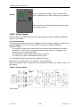
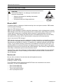
ESAB ESABFeed 30L-4i is a reliable wire feeder designed for professional welding applications. With its robust construction and advanced features, it offers precise wire feeding control and consistent arc performance. It handles a wide range of wire types and diameters, making it suitable for various welding tasks. The user-friendly control panel enables easy setting adjustments, enhancing productivity and ensuring optimal welding results.
ESAB ESABFeed 30L-4i is a reliable wire feeder designed for professional welding applications. With its robust construction and advanced features, it offers precise wire feeding control and consistent arc performance. It handles a wide range of wire types and diameters, making it suitable for various welding tasks. The user-friendly control panel enables easy setting adjustments, enhancing productivity and ensuring optimal welding results.


-
 1
1
-
 2
2
-
 3
3
-
 4
4
-
 5
5
-
 6
6
-
 7
7
-
 8
8
-
 9
9
-
 10
10
-
 11
11
-
 12
12
-
 13
13
-
 14
14
-
 15
15
-
 16
16
-
 17
17
-
 18
18
-
 19
19
-
 20
20
-
 21
21
-
 22
22
-
 23
23
-
 24
24
-
 25
25
-
 26
26
-
 27
27
-
 28
28
-
 29
29
-
 30
30
-
 31
31
-
 32
32
-
 33
33
-
 34
34


ESAB ESABFeed 30L-4i User manual
- Category
- Welding System
- Type
- User manual
- This manual is also suitable for
ESAB ESABFeed 30L-4i is a reliable wire feeder designed for professional welding applications. With its robust construction and advanced features, it offers precise wire feeding control and consistent arc performance. It handles a wide range of wire types and diameters, making it suitable for various welding tasks. The user-friendly control panel enables easy setting adjustments, enhancing productivity and ensuring optimal welding results.
Ask a question and I''ll find the answer in the document
Finding information in a document is now easier with AI
Related papers
-
ESAB AristoFeed 30/48 Troubleshooting instruction
-
-
ESAB YardFeed 2000 User manual
-
ESAB ESAB YardFeed 200 User manual
-
ESAB Powercut 700 User manual
-
-
-
-
ESAB ESABMig 300i User manual
-
ESAB MA23 User manual