Comtech EF Data SLM-7650 Specification
- Category
- Networking
- Type
- Specification

Part Number MN/SLM7650.IOM
Revision 4
SL
M
-
765
0
Satellite Modem
Installation and O
p
eration Manual


Copyright © Comtech EF Data, 2000, 2001, 2002, 2003. All rights reserved. Printed in the USA.
Comtech EF Data, 2114 West 7th Street, Tempe, Arizona 85281 USA, (480) 333-2200, FAX: (480) 333-2161.
SLM-7650
Satellite Modem
Installation and Operation Manual
Part Number MN/SLM7650.IOM
Revision 4
September 10, 2005
Comtech EF Data is an ISO 9001
Registered Company.

SLM-7650 Satellite Modem Revision 4
Preface MN/SLM7650.IOM
ii
Customer Support
Contact the Comtech EF Data Customer Support Department for:
• Product support or training
• Information on upgrading or returning a product
• Reporting comments or suggestions concerning manuals
A Customer Support representative may be reached at:
Comtech EF Data
Attention: Customer Support Department
2114 West 7th Street
Tempe, Arizona 85281 USA
(480) 333-2200 (Main Comtech EF Data Number)
(480) 333-4357 (Customer Support Desk)
(480) 333-2161 FAX
or, E-Mail can be sent to the Customer Support Department at:
service@comtechEF Data.com
Contact us via the web at www.comtechEF Data.com
.
1. To return a Comtech EF Data product (in-warranty and out-of-warranty) for
repair or replacement:
2. Request a Return Material Authorization (RMA) number from the Comtech EF
Data Customer Support Department.
3. Be prepared to supply the Customer Support representative with the model
number, serial number, and a description of the problem.
4. To ensure that the product is not damaged during shipping, pack the product in
its original shipping carton/packaging.
5. Ship the product back to Comtech EF Data. (Shipping charges should be
prepaid.)
For more information regarding the warranty policies referred to the Warranty Policy at
the end of this chapter.

iii
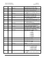
Table of Contents
CHAPTER 1. INTRODUCTION................................................................................ 1–1
1.1 Overview......................................................................................................................................................1–1
1.2 Description ..................................................................................................................................................1–2
1.2.1 Definition of Modulator Functions ..........................................................................................................1–3
1.2.2 Definition of Demodulator Functions ......................................................................................................1–3
1.2.3 Definition of Interface/M&C Functions...................................................................................................1–4
1.2.4 Additional Features ..................................................................................................................................1–4
1.3 Operating Modes ........................................................................................................................................1–5
1.4 Options ........................................................................................................................................................1–5
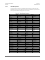
1.5 System Specifications Summary................................................................................................................1–6
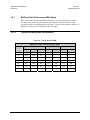
1.5.1
Bit Error Rate Performance with Noise ...................................................................................................1–8
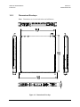
1.5.2 Dimensional Envelope ...........................................................................................................................1–10
CHAPTER 2. INSTALLATION ................................................................................. 2–1
2.1 Unpacking ...................................................................................................................................................2–1
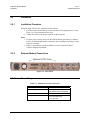
2.2 Installation ..................................................................................................................................................2–2
2.2.1 Installation Procedure...............................................................................................................................2–2
2.2.2 External Modem Connections..................................................................................................................2–2

SLM-7650 Satellite Modem Revision 4
Preface MN/SLM7650.IOM
iv
CHAPTER 3. OPERATION ....................................................................................... 3-1
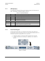
3.1 Front Panel.................................................................................................................................................. 3-1
3.1.1 LED Indicators......................................................................................................................................... 3-2
3.1.2 Front Panel Keypad.................................................................................................................................. 3-2
3.2 Front Panel Operation ............................................................................................................................... 3-3
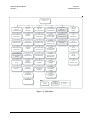
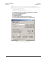
3.2.1 Front Panel Menu Operation.................................................................................................................... 3-3
3.2.2 Configuration ........................................................................................................................................... 3-5
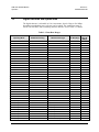
3.3
Digital Data Rate and Symbol Rate .......................................................................................................... 3-6
3.4
Menus .......................................................................................................................................................... 3-8
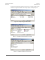
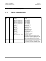
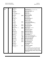
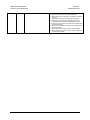
3.4.1 Configuration Menu................................................................................................................................. 3-8
3.4.1.1 Modulator Menu .............................................................................................................................. 3-20
3.4.1.2 Demodulator Menu .......................................................................................................................... 3-21
3.4.1.3 Interface Menu................................................................................................................................. 3-25
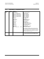
3.4.1.4 Local AUPC Menu .......................................................................................................................... 3-26
3.4.1.5 Save Menu ....................................................................................................................................... 3-20
3.4.1.6 Recall Menu..................................................................................................................................... 3-21
3.4.2 Monitor Menu ........................................................................................................................................ 3-20
3.4.3 Faults/Alarms Menu............................................................................................................................... 3-21
3.4.3.1 Modulator Faults.............................................................................................................................. 3-22
3.4.3.2 Demodulator Faults.......................................................................................................................... 3-22
3.4.3.3 Transmit Interface Faults ................................................................................................................. 3-23
3.4.3.4 Receive Interface Faults................................................................................................................... 3-23
3.4.3.5 Common Equipment Faults ............................................................................................................. 3-24
3.4.3.6 IDR Backward Faults....................................................................................................................... 3-24
3.4.4 Stored Faults/Alarms Menu ................................................................................................................... 3-25
3.4.5 Remote AUPC Menu ............................................................................................................................. 3-26
3.4.5.1 Remote AUPC Configuration .......................................................................................................... 3-26
3.4.5.2 Remote AUPC Monitor ................................................................................................................... 3-26
3.4.6 Utility Menu........................................................................................................................................... 3-27
3.4.6.1 Utility Modulator Menu................................................................................................................... 3-28
3.4.6.2 Utility Demodulator Menu............................................................................................................... 3-29
3.4.6.3 Utility Interface Menu...................................................................................................................... 3-30
3.4.6.4 Utility System Menu ........................................................................................................................ 3-31
3.4.6.5 Utility Modem Type Menu .............................................................................................................. 3-33
3.5 Modes of Operation.................................................................................................................................. 3-34
3.5.1 7650-00 Operation ................................................................................................................................. 3-34
3.5.2 7650-02 Operation ................................................................................................................................. 3-35
3.5.3 IDR Operation........................................................................................................................................ 3-37
3.5.4 IBS Operation ........................................................................................................................................ 3-39
3.5.5 VSAT-IBS Operation............................................................................................................................. 3-41
3.5.6 IBS-309 Operation ................................................................................................................................. 3-43
3.5.7 ASYNC/AUPC Operation ..................................................................................................................... 3-45
3.5.8 EFD Operation ....................................................................................................................................... 3-47
3.5.9 Custom Operation .................................................................................................................................. 3-49

SLM-7650 Satellite Modem Revision 4
Preface MN/SLM7650.IOM
v
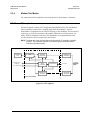
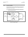
CHAPTER 4. THEORY OF OPERATION ................................................................ 4–1
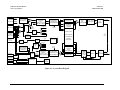
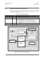
4.1 Overview......................................................................................................................................................4–1
4.2 Built in Test.................................................................................................................................................4–1
4.3 Definitions ...................................................................................................................................................4–3
4.3.1 Differential Encoding/Decoding ..............................................................................................................4–3
4.3.2 Scrambler/Descrambler............................................................................................................................4–3
4.3.2.1 Self-Synchronizing Scrambler/Descrambler...................................................................................... 4-3
4.3.2.2 Synchronous Scrambler/Descrambler................................................................................................ 4-4
4.3.3 Encoding/Decoding..................................................................................................................................4–4
4.3.3.1 Convolutional/Viterbi (CEVD).......................................................................................................... 4-4
4.3.3.2 Reed-Solomon.................................................................................................................................... 4-5
4.3.3.3 Trellis Coding .................................................................................................................................... 4-6
4.3.3.4 Turbo Products Codec (Hardware Option) ........................................................................................ 4-7
4.3.3.5 Uncoded Operation (No FEC) ........................................................................................................... 4-9
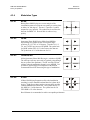
4.3.4 Modulation Types ..................................................................................................................................4–10
4.3.4.1 BPSK ............................................................................................................................................... 4-10
4.3.4.2 QPSK ............................................................................................................................................... 4-10
4.3.4.3 Offset QPSK .................................................................................................................................... 4-10
4.3.4.4 8-PSK............................................................................................................................................... 4-10
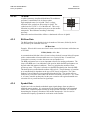
4.3.4.5 16-QAM........................................................................................................................................... 4-11
4.3.5 Bit Error Rate.........................................................................................................................................4–11
4.3.6 Symbol Rate...........................................................................................................................................4–11
4.3.7 Symbol Rate Calculations......................................................................................................................4–12
4.4 Theory of Operation.................................................................................................................................4–13
4.4.1 Modulator...............................................................................................................................................4–13
4.4.2 Demodulator...........................................................................................................................................4–14
4.4.3 Baseband Interface.................................................................................................................................4–17
4.4.3.1 Monitor and Control ........................................................................................................................ 4-17
4.4.3.2 Transmit and Receive Baseband ...................................................................................................... 4-17
4.4.3.3 Reference and Clock Distribution.................................................................................................... 4-24
CHAPTER 5. MAINTENANCE................................................................................. 5–1
5.1 Modem Firmware Upgrade .......................................................................................................................5–1
5.2 Fault Isolation .............................................................................................................................................5–4
5.2.1 Fan............................................................................................................................................................5–4
5.2.2 M & C Battery..........................................................................................................................................5–4
5.2.3 Faults/Alarms...........................................................................................................................................5–4
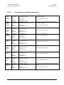
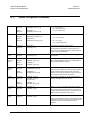
5.2.4 Fault/Alarm Display and Description.......................................................................................................5–8
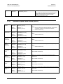
5.2.5 Fault/Alarm Analysis ...............................................................................................................................5–9
5.2.5.1 Modulator Faults................................................................................................................................ 5-9
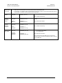
5.2.5.2 Demodulator Faults.......................................................................................................................... 5-10
5.2.5.3 Transmit Interface Faults ................................................................................................................. 5-10
5.2.5.4 Receive Interface Faults................................................................................................................... 5-12
5.2.5.5 Common Equipment Faults ............................................................................................................. 5-13

SLM-7650 Satellite Modem Revision 4
Preface MN/SLM7650.IOM
vi
5.3 Modem Performance Verification Tests.................................................................................................5–14
5.3.1 Modulator Tests .....................................................................................................................................5–15
5.3.1.1 Spectral Shape of the IF Output....................................................................................................... 5-15
5.3.1.2 Carrier Null ...................................................................................................................................... 5-15
5.3.1.3 Spurious using a Spectrum Analyzer ............................................................................................... 5-16
5.3.1.4 Output Frequency............................................................................................................................. 5-16
5.3.1.5 Power Level ..................................................................................................................................... 5-16
5.3.2 Demodulator Tests .................................................................................................................................5–18
5.3.2.1 Dynamic Range................................................................................................................................ 5-18
5.3.2.2 Acquisition Range............................................................................................................................ 5-18
5.3.3 System BER Test ...................................................................................................................................5–18
5.3.4
Modem Test Modes................................................................................................................................5–19
5.3.4.1 IF Loopback..................................................................................................................................... 5-19
5.3.4.2 Base Band Loopback ....................................................................................................................... 5-20
5.3.4.3 Carrier Modes .................................................................................................................................. 5-21
5.3.4.4 Reed-Solomon Correction OFF ....................................................................................................... 5-22
5.3.4.5 2047 and MIL-188 Test Patterns...................................................................................................... 5-22
APPENDIX A. REMOTE CONTROL OPERATION..................................................B–1
GLOSSARY .................................................................................................................g-1

SLM-7650 Satellite Modem Revision 4
Preface MN/SLM7650.IOM
vii
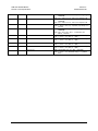
Figures
Figure 1-1. SLM-7650 Satellite Modem...................................................................................................................1–1
Figure 1-2. Dimensional Envelope...........................................................................................................................1–8
Figure 2-1. Rear Panel ..............................................................................................................................................2–2
Figure 3-1. SLM-7650 Front Panel........................................................................................................................... 3-1
Figure 3-2. Keypad................................................................................................................................................... 3-2
Figure 3-3. Main Menu............................................................................................................................................. 3-4
Figure 4-1. System Block Diagram ..........................................................................................................................4–2
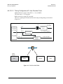
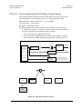
Figure 4-2. User Provides Clock ............................................................................................................................4–25
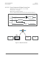
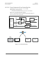
Figure 4-3. Modem Provides Clock........................................................................................................................4–26
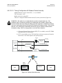
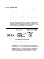
Figure 4-4. Modem Clocks Internally.....................................................................................................................4–27
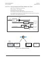
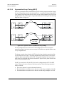
Figure 4-5. Slave Modem-Loop Timed ..................................................................................................................4–28
Figure 4-6. EXT Master Clock as Source...............................................................................................................4–29
Figure 4-7. User Provides Data Only......................................................................................................................4–30
Figure 4-8. Internal SCT Clock Selection ..............................................................................................................4–31
Figure 4-9. Separate Links vs Asymmetrical Loop Timing....................................................................................4–32
Figure 5-1. Reflash Program Window......................................................................................................................5–2
Figure 5-2. Example of Upgrade File Location........................................................................................................5–3
Figure 5-3. Example of Reflash Program File Location...........................................................................................5–3
Figure 5-4. Example of USB Drivers File Location .................................................................................................5–3
Figure 5-5. Modem Verification Test Setup...........................................................................................................5–14
Figure 5-6. DUAL Test Mode ................................................................................................................................5–15
Figure 5-7. OFFSET Test Mode.............................................................................................................................5–16
Figure 5-8. CENTER Test Mode............................................................................................................................5–17
Figure 5-9. IF Loopback.........................................................................................................................................5–19
Figure 5-10. Baseband Loopback...........................................................................................................................5–20

SLM-7650 Satellite Modem Revision 4
Preface MN/SLM7650.IOM
viii
Tables
Table 1-1 Operating Modes......................................................................................................................................1–5
Table 1-2 SLM-7650 Options...................................................................................................................................1–5
Table 1-3. System Specifications Summary ..............................................................................................................1–6
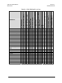
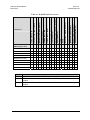
Table 1-4. Viterbi Decoder BER ..............................................................................................................................1–8
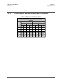
Table 1-5. High Order Modulation Options .............................................................................................................1–9
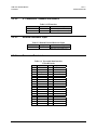
Table 2-1. Modem Rear Panel Connectors...............................................................................................................2–2
Table 2-2. IF Interface...............................................................................................................................................2–3
Table 2-3. Modem External Reference Input ...........................................................................................................2–3
Table 2-4. Terrestrial Data Interface 37-Pin D Female ............................................................................................2–3
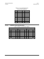
Table 2-5. Terrestrial Data Interface 25-Pin D Female (Optional)...........................................................................2–4
Table 2-6. Remote Control Interface (M&C) ...........................................................................................................2–4
Table-2-7. Asynchronous Data Interface..................................................................................................................2–5
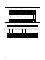
Table 2-8. Fault/Alarm Status Interface ...................................................................................................................2–5
Table 2-9. 50 Pin Sub-D Female Interface Connector..............................................................................................2–6
Table 2-10. 15-Pin Sub-D Female (G.703 Balanced)...............................................................................................2–7
Table 2-11. 75Ω BNC Connectors (G.703 Unbalanced) ..........................................................................................2–7
Table 3-1. Front Panel Indicators ............................................................................................................................. 3-2
Table 3-2. Keypad Functions.................................................................................................................................... 3-3
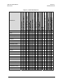
Table 3-3. Data Rate Ranges .................................................................................................................................... 3-6
Table 3-4. 7650-00 Default Parameters.................................................................................................................. 3-35
Table 3-5. 7650-02 Default Parameters.................................................................................................................. 3-36
Table 3-6. IDR Default Parameters ........................................................................................................................ 3-38
Table 3-7. IBS Default Parameters......................................................................................................................... 3-40
Table 3-8. VSAT-IBS Default Parameters ............................................................................................................. 3-42
Table 3-9. IBS-309 Default Parameters.................................................................................................................. 3-44
Table 3-10. ASYNC/AUPC Default Parameters .................................................................................................... 3-46
Table 3-11. EFD Default Parameters...................................................................................................................... 3-48
Table 4-1. Viterbi Decoding Summary.....................................................................................................................4–5
Table 4-2. Concatenated RS Coding Summary ........................................................................................................4–6
Table 4-3. 8PSK/TCM Coding Summary.................................................................................................................4–7
Table 4-4. Available TPC Modes ..............................................................................................................................4–8
Table 4-5. Turbo Product Coding processing delay comparison...............................................................................4–8
Table 4-6. Reed-Solomon Factor............................................................................................................................4–12
Table 4-7. Delay Variations for Inclined Orbit Satellites .......................................................................................4–34
Table 4-8. Recommended Buffer Size....................................................................................................................4–34
Table 5-1. SLM-7650 Fault Tree..............................................................................................................................5–5
Table 5-2. Modulator Fault Information...................................................................................................................5–9
Table 5-3. Demodulator Fault Information.............................................................................................................5–10
Table 5-4. Transmit Interface Fault Information ....................................................................................................5–11
Table 5-5. Receive Interface Fault Information......................................................................................................5–12
Table 5-6. Common Equipment Fault Information ................................................................................................5–13
Table 5-7. Test Equipment Required......................................................................................................................5–14
Table 5-8. Conversion to S/N and E
b
/N
0
Chart .....................................................................................................5–23
Table 5-9. Reed-Solomon Overhead Correction Factor .........................................................................................5–23

SLM-7650 Satellite Modem Revision 4
Preface MN/SLM7650.IOM
ix
About this Manual
This manual describes the installation and operation for the Comtech EF Data SLM-7650
Satellite Modem. This is a technical document intended for earth station engineers,
technicians, and operators responsible for the operation and maintenance of the SLM-
7650.
Related Documents
Standards (Military)
MIL-STD-188-165
Interoperability and Performance Standards for SHF Communications PSK Modems (FDMA
Operation)
MIL-STD-810F
Environmental Test Method and Engineering Guidelines
MIL-STD-1686C
Electrostatic Discharge Control Program for Protection of Electrical and Electronic Parts,
Assemblies and Equipment (Excluding Electrically Initiates Explosive Devices) Metric
Standards (Federal)
FED-STD-313
Material Safety Data, Transportation Data and Disposal Data for Hazardous Materials
Furnished to Government Activities
Standards (General)
EIA-422
Electrical Characteristics of Balanced Voltage Digital Interface Circuits
EIA-485
Standard for Electrical Characteristics of Generators and Receivers for use in Balanced
Digital Multi-point Systems
EIA/TIA-530
High Speed 24-Position Interface for Data Terminal Equipment and Data Circuit-
Terminating Equipment
IESS-308
Performance Characteristics for Intermediate Data Rate (IDR) Digital Carriers
IESS-309
QPSK/FDMA Performance Characteristics for Intelsat Business Service (IBS)
IESS-310
Performance Characteristics for Intermediate Data Rate using 8PSK 2/3
(Standard A, B, C, E and F Earth Stations)
ANSI/J-STD-001A
Joint Industry Standard Requirements for Soldered Electrical and Electronic Assemblies
ANSI/VITA, 3-1995
American National Standard for Board Level Live Insertion for VME.
ISO 9001
Quality System

SLM-7650 Satellite Modem Revision 4
Preface MN/SLM7650.IOM
x
Comtech EF Data Specifications
SP/9710
SP/9710-1
Comtech EF Data Specification, SLM-7650 Satellite Modem
Comtech EF Data Specification, SLM-7650 Remote Control Protocol Specification
Conventions and References
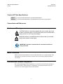
Cautions and Warnings
CAUTION
CAUTION indicates a hazardous situation that, if not avoided, may result
in minor or moderate injury. CAUTION may also be used to indicate other
unsafe practices or risks of property damage.
WARNING
WARNING indicates a potentially hazardous situation that, if not avoided,
could result in death or serious injury.
IMPORTANT
IMPORTANT indicates a statement that is associated with the task
being performed.
Metric Conversion
Metric conversion information is located on the inside back cover of this manual. This
information is provided to assist the operator in cross-referencing English to Metric
conversions.
Recommended Standard Designations
Recommended Standard (RS) Designations are equivalent to the Electronic Industries
Association (EIA). Either reference is satisfactory, except manuafacturer only will
reference one of the designators thru-out the manual.

SLM-7650 Satellite Modem Revision 4
Preface MN/SLM7650.IOM
xi
Trademarks
Product names mentioned in this manual may be trademarks or registered trademarks of
their respective companies and are hereby acknowledged.
Reporting Comments or Suggestions Concerning this Manual
Comments and suggestions regarding the content and design of this manual will be
appreciated. To submit comments, please contact the Comtech EF Data Customer
Support Department.
European EMC Directive
In order to meet the European Electro-Magnetic Compatibility (EMC) Directive
(EN55022, EN50082-1), properly shielded cables for DATA I/O are required. More
specifically, these cables must be shielded from end-to-end, ensuring a continuous
ground shield.
The following information is applicable for the European Low Voltage Directive
(EN60950):
<HAR> Type of power cord required for use in the European Community.
!
CAUTION: Double-pole/Neutral Fusing
ACHTUNG: Zweipolige bzw. Neutralleiter-Sicherung
International Symbols:
Alternating Current.
Fuse.
Safety Ground.
Chassis Ground.
NOTE: For additional symbols, refer to “Cautions and Warnings” listed earlier in this
preface.

SLM-7650 Satellite Modem Revision 4
Preface MN/SLM7650.IOM
xii
Warranty Policy
This Comtech EF Data product is warranted against defects in material and workmanship
for a period of one year from the date of shipment. During the warranty period, Comtech
EF Data will, at its option, repair or replace products that prove to be defective.
For equipment under warranty, the customer is responsible for freight to Comtech EF
Data and all related custom, taxes, tariffs, insurance, etc. Comtech EF Data is responsible
for the freight charges only for return of the equipment from the factory to the customer.
Comtech EF Data will return the equipment by the same method (i.e., Air, Express,
Surface) as the equipment was sent to Comtech EF Data.
Limitations of Warranty
The foregoing warranty shall not apply to defects resulting from improper installation or
maintenance, abuse, unauthorized modification, or operation outside of environmental
specifications for the product, or, for damages that occur due to improper repackaging of
equipment for return to Comtech EF Data.
No other warranty is expressed or implied. Comtech EF Data specifically disclaims the
implied warranties of merchantability and fitness for particular purpose.
Exclusive Remedies
The remedies provided herein are the buyer's sole and exclusive remedies. Comtech EF
Data shall not be liable for any direct, indirect, special, incidental, or consequential
damages, whether based on contract, tort, or any other legal theory.
Disclaimer
Comtech EF Data has reviewed this manual thoroughly in order that it will be an easy-to-
use guide to your equipment. All statements, technical information, and
recommendations in this manual and in any guides or related documents are believed
reliable, but the accuracy and completeness thereof are not guaranteed or warranted, and
they are not intended to be, nor should they be understood to be, representations or
warranties concerning the products described. Further, Comtech EF Data reserves the
right to make changes in the specifications of the products described in this manual at any
time without notice and without obligation to notify any person of such changes.
If there are any questions regarding your equipment or the information in this manual,
please contact the Comtech EF Data Customer Support Department.

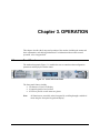
1–1
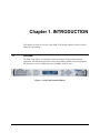
Chapter 1. INTRODUCTION
This chapter provides an overview of the SLM-7650 satellite modem, referred to in this
manual as “the modem.”
1.1 Overview
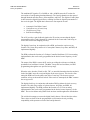
The SLM-7650 (Figure 1-1) interfaces between terrestrial fixed-rate data terminal
equipment, with data rates between 9.6 kbps and 20 Mbps, and RF converter equipment
that interfaces at 50 to 90 MHz and 100 to 180 MHz on the IF ports.
Figure 1-1. SLM-7650 Satellite Modem

SLM-7650 Satellite Modem Revision 4
Introduction MN/SLM7650.IOM
1–2
1.2 Description
The modem is a high performance, full-duplex, digital-vector, modulator/demodulator
that meets the requirements of most systems encountered in the commercial and
government Satellite Communications industry including:
• Government/Defense
• DSCS II
• DSCS III
• NATO III
• Commercial
• INTELSAT
• EUTELSAT
• PANAMSAT
• NEW SKIES
• SES Americom
• Others
The modem is ideal for tri-band terminals requiring both commercial and government
access methods. Additionally, the modem can be used for virtually any closed network
satellite communication system. The modem is compliant with MIL-STD-188-165 over
the data rate range specified within this specification. The modem is also compliant to the
INTELSAT Earth Station Standards (IESS) -308, -309, and –310 specifications for the
following:
• Intermediate Data Rate (IDR)
• INTELSAT Business Services (IBS)
The modem is compatible with the following modems within the operating parameters
defined in this manual:
• OM-73(V)
• MD-1340
• MD-1352(P)/U (BEM-7650)
• SLM-8650
• SLM-3650
• SLM-6650
• SLM-4650
• LM-46/4046
• MD-945 (OM-73 interoperability mode only; orderwire not supported)

SLM-7650 Satellite Modem Revision 4
Introduction MN/SLM7650.IOM
1–3
1.2.1 Definition of Modulator Functions
The modulator section accepts data and clock from a digital signal source and after
appropriate processing modulates the information on an IF carrier. The modulator
provides the following functions:
1. Interface that receives digital signals, including data, clock, frequency reference, and
control from a digital signal source.
2. A function that scrambles the data.
3. A differential encoder.
4. Forward Error Correction (FEC) encoding.
5. Perform BPSK, QPSK, OQPSK, 8-PSK, and 16-QAM modulation.
6. An output IF signal.
7. Setup, control, monitoring, and upgrade of the modulator.
8. Built-in Test (BIT) function that detects fault conditions and allows faults to be
isolated to the modulator. This includes provision for an IF loopback and a transmit
interface test data pattern.
1.2.2 Definition of Demodulator Functions
The demodulator section accepts a signal from an Intermediate Frequency (IF) carrier,
demodulate the IF carrier, and after appropriate processing, outputs the data and clock to
the user. The demodulator provides the following functions:
1. An input for the IF signal.
2. Acquisition functions and a function to demodulate BPSK, QPSK, OQPSK, 8-PSK,
and 16-QAM carriers.
3. Forward Error Correction (FEC) decoding.
4. A differential decoder.
5. Descrambles the received data.
6. Digital interface to output digital signals, including data, and associated clock.
7. Setup, control, monitoring, and upgrade of the demodulator.
8. Built-in Test (BIT) function that detects fault conditions and allow faults to be
isolated to the demodulator. This includes provision for an IF loopback and a way to
measure the error using a test data pattern.

SLM-7650 Satellite Modem Revision 4
Introduction MN/SLM7650.IOM
1–4
1.2.3 Definition of Interface/M&C Functions
The interface/M&C section consists of a device having the following identifiable
functions:
1. Terrestrial Interface, defined by EIA-422 (balanced circuits) [MIL-STD-188-114A
Type II and III compatible].
2. Multiplex/Demultiplex an asynchronous data channel onto the primary data channel.
3. Provide Intelsat compatible Overhead Framing for Open Network interoperability.
4. Provide a buffer that can be clocked by the Tx, terrestrial source, an external
reference, internal clock, or from the recovered clock from the satellite link.
5. Monitor the modem status without interrupting service
6. Provide an interface for control of the modem parameters via the front panel or serial
remote control interface
1.2.4 Additional Features
The modem contains the following additional features:
• Fully Accessible System Topology (FAST)
• Built-in self test (BIST)
• Asymmetrical loop timing (ASLT)
• Selectable near or far end, baseband loopback with ASYNC overhead option enabled
• Intelsat compliant Reed-Solomon Codec
• ASYNChronous Channel Unit Overhead (ASYNC)
• Automatic Uplink Power Control (AUPC)
• Turbo Product Code (TPC) Forward Error Correction (FEC) (Hardware Option)
• G.703 Optional Interface with Overhead Card (AS/10175), 50-pin interface and
access to IESS ESC

SLM-7650 Satellite Modem Revision 4
Introduction MN/SLM7650.IOM
1–5
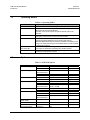
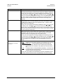
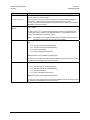
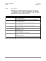
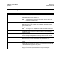
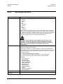
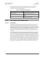
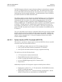
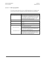
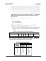
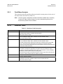
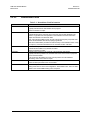
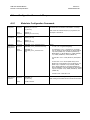
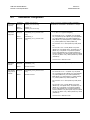
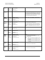
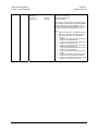
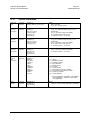
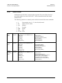
1.3 Operating Modes
Table 1-1 Operating Modes
Modes Description
7650-00 This is the basic OM-73 compatibility mode.
7650-02 This mode is compatible with the SLM8650-02 modem up to the 8.448
Mbps data rate limit of the SLM-8650.
Operation in this mode requires the optional ASYNC option to be
activated.
EFD This is the basic closed network non-OM73 operating mode compatible
with legacy-closed network Comtech EF Data modems.
ASYNC This mode allows for an asynchronous overhead channel to be
multiplexed and demultiplexed onto the primary data channel.
Automatic Uplink Power Control (AUPC) is available to maintain the link
margin of a duplex link during the normal fades that occur with a satellite
communication network.
IDR, IBS, IBS-309,
and VSAT-IBS
These modes of operation are typical open network operating modes
used within the INTELSAT and EUTELSAT satellite networks.
Custom This mode of operation enables the programming of the modem for
emulating most proprietary modems.
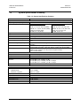
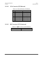
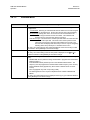
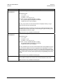
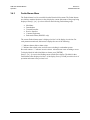
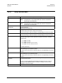
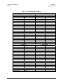
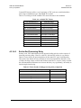
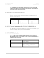
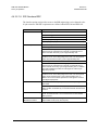
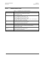
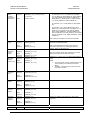
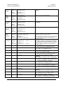
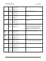
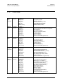
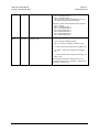
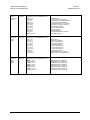
1.4 Options
Table 1-2 SLM-7650 Options
Option Part No. Description Remarks
PL/9709-1 90 – 264 VAC TNC Standard Chassis Configuration
PL/9709-2 90 – 264 VAC BNC Option
SS/SLM7650-0009
SS/SLM7650-0010
Tx and Rx Standard
SS/SLM7650-0010 Rx Only Option
System Configuration
SS/SLM7650-0009 Tx Only Option
PL/9685-1 37-pin EIA-449 Standard Baseband Interface
PL/9685-2 25-pin EIA-530 Option
BPSK, QPSK, OQPSK Standard
SS/SLM7650-0004 BPSK, QPSK, OQPSK, 8-PSK Option
Modulation Type
SS/SLM7650-0004
SS/SLM7650-0005
BPSK, QPSK, OQPSK,
8-PSK, 16-QAM
Option
9.6 kbps to 10 Mbps Standard Variable Data Rate
SS/SLM7650-0003 9.6 kbps to 20 Mbps Option
SS/SLM7650-0006 IDR/IBS Option
SS/SLM7650-0007 ASYNC/AUPC Option
Overhead Framing
SS/SLM7650-0006
SS/SLM7650-0007
IDR/IBS/ASYNC/AUPC Option
Reed-Solomon
(IESS Fixed)
SS/SLM7650-0008 Tx and Rx Option
Turbo FEC PL/9652-1 Tx and Rx Option
G.703 Option
Overhead Interface
PL/10175-1
PL/10175-2
G.703, 50 pin, access to IESS
ESC
Option

SLM-7650 Satellite Modem Revision 4
Introduction MN/SLM7650.IOM
1–6
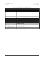
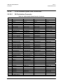
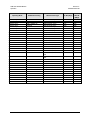
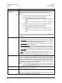
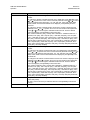
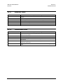
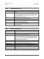
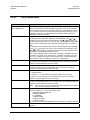
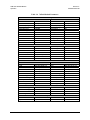
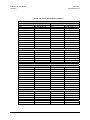
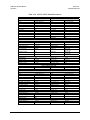
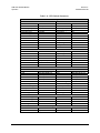
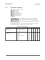
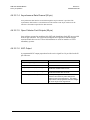
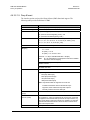
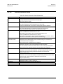
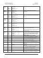
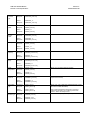
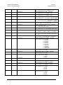
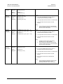
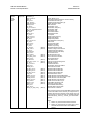
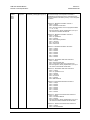
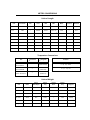
1.5 System Specifications Summary
Table 1-3. System Specifications Summary
Characteristic Specification
System
Operating Frequency Range 50 to 90, 100 to 180 MHz, in 1 Hz steps
Modulation Types Non-Turbo Modulation Types
BPSK: 1/1 and 1/2 (CEVD)
QPSK: 1/1, 1/2, 3/4, and 7/8 (CEVD)
OQPSK: 1/1, 1/2, 3/4, and 7/8 (CEVD)
8-PSK: 2/3 and 5/6 (TCM)
16-QAM: 3/4, 7/8 (CEVD)
Turbo Modulation Types
BPSK: 5/16 and 21/44
QPSK: 3/4, 7/8, 17/18, and 21/44
OQPSK: 3/4, 7/8, 17/18, and 21/44
8-PSK: 3/4, 7/8, and 17/18
16-QAM: 3/4 and 7/8
Digital Data Rate 9.6 kbps to 20.0 Mbps, in 1 bps steps
Symbol Rate 9.6 ks/s to 10 Ms/s
External Reference In 1, 5, 10, or 20 MHz, selectable
Internal Reference Stability
± 2 x 10
-7
Scrambling V.35 scrambler variations to meet MIL-STD-188-165 and IESS-308, -309,
-310.
IDR/IBS Framing Compatibility Support for IDR and IBS framing. Allows basic IDR/IBS open network
operation.
Built-in Test (BIT) Fault and status reporting, BER performance monitoring, IF loopback,
programmable test modes, Tx/Rx 2047 pattern provides and estimated BER.
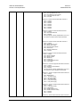
Summary Faults Reported via 15-pin D sub,
FORM C relay contacts for Tx, Rx, Common equipment faults,
and Tx and Rx Alarms.
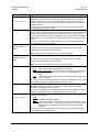
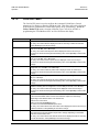
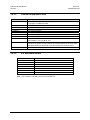
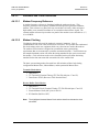
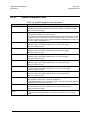
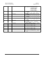
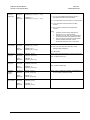
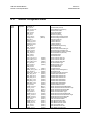
Modulation
Output Power +5 to –30 dBm, adjustable in 0.1 dB steps
Output Return Loss 17 dB
Output Impedance
50Ω
Spurious 0 to 500 MHz (-5 to –30 dBm) –5 dBc
0 to 500 MHz (+5 tp –20 dBm) –50 dBc > 64 kbps
o to 500 MHz (+5 to –20 dBm) _45 dBc < 64 kbps
Tx Clock Source INT, Tx Terrestrial, and Data Source Sync
Output Connector TNC
Demodulation
Input Power:
Desired Carrier
Maximum Composite
-15 to –55 dBm
0 dBm or +40 dBc
Input Impedance
50Ω
Input Connector TNC
Carrier Acquisition Range
± 35 kHz, selectable
Input Return Loss 17 dB minimum
Buffer Clock INT, EXTERNAL, Tx Terrestrial, Rx Satellite
Elastic Buffer 32 to 1,048,576 bits selectable
Page is loading ...
Page is loading ...
Page is loading ...
Page is loading ...
Page is loading ...
Page is loading ...
Page is loading ...
Page is loading ...
Page is loading ...
Page is loading ...
Page is loading ...
Page is loading ...
Page is loading ...
Page is loading ...
Page is loading ...
Page is loading ...
Page is loading ...
Page is loading ...
Page is loading ...
Page is loading ...
Page is loading ...
Page is loading ...
Page is loading ...
Page is loading ...
Page is loading ...
Page is loading ...
Page is loading ...
Page is loading ...
Page is loading ...
Page is loading ...
Page is loading ...
Page is loading ...
Page is loading ...
Page is loading ...
Page is loading ...
Page is loading ...
Page is loading ...
Page is loading ...
Page is loading ...
Page is loading ...
Page is loading ...
Page is loading ...
Page is loading ...
Page is loading ...
Page is loading ...
Page is loading ...
Page is loading ...
Page is loading ...
Page is loading ...
Page is loading ...
Page is loading ...
Page is loading ...
Page is loading ...
Page is loading ...
Page is loading ...
Page is loading ...
Page is loading ...
Page is loading ...
Page is loading ...
Page is loading ...
Page is loading ...
Page is loading ...
Page is loading ...
Page is loading ...
Page is loading ...
Page is loading ...
Page is loading ...
Page is loading ...
Page is loading ...
Page is loading ...
Page is loading ...
Page is loading ...
Page is loading ...
Page is loading ...
Page is loading ...
Page is loading ...
Page is loading ...
Page is loading ...
Page is loading ...
Page is loading ...
Page is loading ...
Page is loading ...
Page is loading ...
Page is loading ...
Page is loading ...
Page is loading ...
Page is loading ...
Page is loading ...
Page is loading ...
Page is loading ...
Page is loading ...
Page is loading ...
Page is loading ...
Page is loading ...
Page is loading ...
Page is loading ...
Page is loading ...
Page is loading ...
Page is loading ...
Page is loading ...
Page is loading ...
Page is loading ...
Page is loading ...
Page is loading ...
Page is loading ...
Page is loading ...
Page is loading ...
Page is loading ...
Page is loading ...
Page is loading ...
Page is loading ...
Page is loading ...
Page is loading ...
Page is loading ...
Page is loading ...
Page is loading ...
Page is loading ...
Page is loading ...
Page is loading ...
Page is loading ...
Page is loading ...
Page is loading ...
Page is loading ...
Page is loading ...
Page is loading ...
Page is loading ...
Page is loading ...
Page is loading ...
Page is loading ...
Page is loading ...
Page is loading ...
Page is loading ...
Page is loading ...
Page is loading ...
Page is loading ...
Page is loading ...
Page is loading ...
Page is loading ...
Page is loading ...
Page is loading ...
Page is loading ...
Page is loading ...
Page is loading ...
Page is loading ...
Page is loading ...
Page is loading ...
Page is loading ...
Page is loading ...
Page is loading ...
Page is loading ...
Page is loading ...
Page is loading ...
Page is loading ...
Page is loading ...
Page is loading ...
Page is loading ...
Page is loading ...
Page is loading ...
Page is loading ...
Page is loading ...
Page is loading ...
Page is loading ...
Page is loading ...
Page is loading ...
Page is loading ...
Page is loading ...
Page is loading ...
Page is loading ...
Page is loading ...
Page is loading ...
Page is loading ...
Page is loading ...
Page is loading ...
Page is loading ...
-
 1
1
-
 2
2
-
 3
3
-
 4
4
-
 5
5
-
 6
6
-
 7
7
-
 8
8
-
 9
9
-
 10
10
-
 11
11
-
 12
12
-
 13
13
-
 14
14
-
 15
15
-
 16
16
-
 17
17
-
 18
18
-
 19
19
-
 20
20
-
 21
21
-
 22
22
-
 23
23
-
 24
24
-
 25
25
-
 26
26
-
 27
27
-
 28
28
-
 29
29
-
 30
30
-
 31
31
-
 32
32
-
 33
33
-
 34
34
-
 35
35
-
 36
36
-
 37
37
-
 38
38
-
 39
39
-
 40
40
-
 41
41
-
 42
42
-
 43
43
-
 44
44
-
 45
45
-
 46
46
-
 47
47
-
 48
48
-
 49
49
-
 50
50
-
 51
51
-
 52
52
-
 53
53
-
 54
54
-
 55
55
-
 56
56
-
 57
57
-
 58
58
-
 59
59
-
 60
60
-
 61
61
-
 62
62
-
 63
63
-
 64
64
-
 65
65
-
 66
66
-
 67
67
-
 68
68
-
 69
69
-
 70
70
-
 71
71
-
 72
72
-
 73
73
-
 74
74
-
 75
75
-
 76
76
-
 77
77
-
 78
78
-
 79
79
-
 80
80
-
 81
81
-
 82
82
-
 83
83
-
 84
84
-
 85
85
-
 86
86
-
 87
87
-
 88
88
-
 89
89
-
 90
90
-
 91
91
-
 92
92
-
 93
93
-
 94
94
-
 95
95
-
 96
96
-
 97
97
-
 98
98
-
 99
99
-
 100
100
-
 101
101
-
 102
102
-
 103
103
-
 104
104
-
 105
105
-
 106
106
-
 107
107
-
 108
108
-
 109
109
-
 110
110
-
 111
111
-
 112
112
-
 113
113
-
 114
114
-
 115
115
-
 116
116
-
 117
117
-
 118
118
-
 119
119
-
 120
120
-
 121
121
-
 122
122
-
 123
123
-
 124
124
-
 125
125
-
 126
126
-
 127
127
-
 128
128
-
 129
129
-
 130
130
-
 131
131
-
 132
132
-
 133
133
-
 134
134
-
 135
135
-
 136
136
-
 137
137
-
 138
138
-
 139
139
-
 140
140
-
 141
141
-
 142
142
-
 143
143
-
 144
144
-
 145
145
-
 146
146
-
 147
147
-
 148
148
-
 149
149
-
 150
150
-
 151
151
-
 152
152
-
 153
153
-
 154
154
-
 155
155
-
 156
156
-
 157
157
-
 158
158
-
 159
159
-
 160
160
-
 161
161
-
 162
162
-
 163
163
-
 164
164
-
 165
165
-
 166
166
-
 167
167
-
 168
168
-
 169
169
-
 170
170
-
 171
171
-
 172
172
-
 173
173
-
 174
174
-
 175
175
-
 176
176
-
 177
177
-
 178
178
-
 179
179
-
 180
180
-
 181
181
-
 182
182
-
 183
183
-
 184
184
-
 185
185
-
 186
186
-
 187
187
-
 188
188
-
 189
189
-
 190
190
-
 191
191
-
 192
192
-
 193
193
-
 194
194


Comtech EF Data SLM-7650 Specification
- Category
- Networking
- Type
- Specification
Ask a question and I''ll find the answer in the document
Finding information in a document is now easier with AI
Related papers
-
 Mocomtech SLM-5650 User manual
-
Comtech EF Data SDM-300A Operating instructions
-
-
Premier Mounts CDM-600 User manual
-
-
-
-
-
-

Other documents
-
 Paradise Datacom P300-IDR Installation & Operating Handbook
-
Audiovox MCS Owner's manual
-
Allen-Heath AP4530 User manual
-
ALLEN & HEATH iDR-in User manual
-
 Paradise P300 User manual
-
E-Mon SUB Series Interval Data Recorders 62-0342-01 User manual
-
-
 Paradise P300 User manual
-
 Ikusu SPI-300 Setup Manual
-
 Mocomtech CiM-25/600L User manual


