Page is loading ...

Table of Contents Page
Section 1 Important Questions to Answer . . . . . . . . . . . . . . .2
– Are you capable of installing this access ladder? . . . . . . . . . . .2
– Does this access ladder meet your needs? . . . . . . . . . . . . . . .
2
– Is your ceiling and joist structure suitable? . . . . . . . . . . . . . . .2
– Do these instructions meet your needs? . . . . . . . . . . . . . .2
Section 2 Checking the Access Ladder Condition . . . . . . . . .3
Section 3 Persons,Tools and Materials Needed . . . . . . . . . . .3
Section 4 Finding a Suitable Location . . . . . . . . . . . . . . . . . .5
Section 5 Cutting a Hole in the Ceiling . . . . . . . . . . . . . . . . . .6
Section 6 Cutting the Ceiling Joists . . . . . . . . . . . . . . . . . . . .7
Section 7 Framing the Rough Opening . . . . . . . . . . . . . . . . . .8
– Installing Headers . . . . . . . . . . . . . . . . . . . . . . . . . . . . . . . . . .
9
– Installing Stringers . . . . . . . . . . . . . . . . . . . . . . . . . . .11
Section 8 Installing Temporary Support Boards . . . . . . . . .12
Section 9 Positioning the Access Ladder . . . . . . . . . . . . . . .12
Section 10 Shimming, Squaring and Nailing
the Access Ladder in Place . . . . . . . . . . . . . . . . . .13
Section 11 Trimming the Access Ladder Legs . . . . . . . . . . . .14
SpaceMaster
®
TURNS EMPTY SPACE INTO STORAGE SPACE!
®
Wood Overhead
Access Ladder
Installation Instructions
FAILURE TO COMPLY WITH ALL INSTRUCTIONS MAY RESULT IN SERIOUS INJURY

Section 1
IMPORTANT QUESTIONS TO ANSWER
2
Read instr
uctions completely before beginning. This is necessary to ensure that you have a suitable location
for the access ladder and the ability to safely and properly install it.
Are you capable of installing this access ladder?
To install this access ladder you should have sawing, squaring, and aligning skills similar to those required to
install a window or a door frame. If you do not have these skills you should hire a professional carpenter to
install this unit (see the Yellow Pages under “Building Contractors, Carpenters, Home Builders, Home
Improvements, or Contractors-General”).
Does this access ladder meet your needs?
This access ladder is for residential use only. Installing this access ladder in commercial buildings and apartments
may violate building codes that require
fire-rated ceilings and prohibit storing materials in the overhead space! Check with your local fire marshal or
building department before installing the access ladder.
The capacity of the access ladder (person plus materials being carried) is 250 pounds for Models W2208,
W2210, W2508 and W2510 and 300 pounds for Models WH2208, WH2210, WH2508 WH2510, WH3008,
and WH3010.
This access ladder is made for the range of ceiling heights shown on the box. Do not install the access ladder
in a ceiling that has a height outside of this range. Altering the access ladder to accommodate other heights
is unsafe.
Figure 1. Conventional roof frame.
Ceiling Joist
Rafter
Conventional Roof Frame
This access ladder can be installed in structures with
conventional wood roof frames (see Figure 1). If a
ceiling is present, you must have an access hole in
the ceiling that allows you to enter the overhead
space for a pre-installation inspection.
Roof support structures that have braces connected
to the ceiling joists or which use trusses (see Figure 2)
cannot be cut without destroying the load-bearing
capacity of that section of the roof. Do not cut joists
that are part of a braced conventional frame or
truss without first consulting an architect or
structural engineer (see the Yellow Pages under
“Architects or Structural Engineers”).
The access ladder should not be installed in a ceiling that has any of the following:
– components of heating/cooling systems
embedded in the ceiling
– joists made of materials other than wood
– metal reinforced plaster
– suspended ceilings.
If your ceiling contains any of the above, do not attempt to install the access ladder. Contact a professional
for assistance with your specific needs (see the Yellow Pages under “Heating and Cooling Contractors,
Building Contractors, Carpenters, Home Builders, Home Improvements, or Contractors-General”).
Do these instructions meet your needs?
These instructions describe how to install the
access ladder parallel or perpendicular to the ceiling joists. Contact a professional if you want the access
ladder installed in some other direction relative to the joists.
Is your ceiling and joist structure suitable for this installation?

(Continued) Section 1
IMPORTANT QUESTIONS TO ANSWER
3
Is your ceiling and joist structure suitable for this installation?
WARNING: DO NOT CUT THESE TYPES OF STRUCTURES
WITHOUT CONSULTING AN ARCHITECT
OR STRUCTURAL ENGINEER.
Ceiling Joist
Rafter
Truss Roof Frame
Figure 2. Truss roof frame and conventional roof frame with braces connected to ceiling joists.
Section 2
CHECKING THE ACCESS LADDER CONDITION
You should have the following items in the access ladder box:
– 1 Access Ladder completely assembled and ready for installation. Do not disassemble to install.
– 1 Pull Cord and Handle if your have: W2200, W2500, W2200-48 or W2500-48 Series Access Ladder.
– 1 Push/Pull Down Rod and Hook Assembly if you have: WH2200, WH2500, or WH3000 Series Access
Ladder.
To save time and prevent accidents, inspect the access ladder for shipping damage before beginning
the installation.
– Check the wooden frame side rails, steps and door panel for splits in the wood.
– Check all metal parts for damage such as bends and cracks.
– Check that all rivets are tight.
If any items are missing or damaged, contact the place of purchase or Werner Ladder Co. at 1-724-588-8600.
Ceiling Joist
Rafter
Conventional Roof Frame with Braces
Connected to Ceiling Joists
Braces
People Required
– 2 people (one of whom is capable of lifting the 70 pound access ladder
into the overhead space)
Materials
– several pieces of joist-sized lumber (the amount depends on the specific installation)
– 2 boards, 1" x 4" x 36", to serve as temporary support boards
– boards to lay across joists to make a working platform in the overhead space
– wood shim stock
– 16d sinker nails (24-60 depending on the specific installation)
– 20d sinker nails are needed for installations where joists are cut
Section 3
PERSONS, TOOLS AND MATERIALS NEEDED

Stepladder
– You need a stepladder that is tall enough so that you can get into the overhead space without
stepping above the working height of the stepladder. The working height of the stepladder is two
steps down from the top.
– Your stepladder must also have a Duty Rating that is greater than the sum of your weight plus
the 70 pound weight of the access ladder.
CAUTION: Be careful when using a stepladder to climb into and out of the overhead space. Have
the second person hold the stepladder so that it does not tip over.
Tools
– flashlight or extension light to provide light in the overhead space
– claw hammer
– pencil
– handsaw
– tape measure
– framing square
– drill
– 1/8" drill bit
– tools to cut a hole in the existing ceiling
Safety Equipment
– gloves
– safety goggles
– dust mask
Before Proceeding: You must have: a) a suitable ceiling and joist structure and b) the persons,
tools and materials needed c) the appropriate ladder for your ceiling height (See Figure 3 and
Table 1 below), and d) a level and flat location in the ceiling.
Goal: To find a location free of hazards and obstructions that will provide room for the installation and use of
the access ladder.
STEP 1. Pick a potential location for installation.
Check for the size of rough opening
shown on the box or in Table 2 on
page 6.
If you are installing the access ladder in
a garage, don’t forget to consider
where cars will be parked.
STEP 2. Check that you have the swing clearance
(SC) needed (see Figure 3 and Table 1).
STEP 3. Check that you have the landing space
(LS) needed to let both legs rest flat on
the floor (see Figure 3 and Table 1).
Section 3
PERSONS, TOOLS AND MATERIALS NEEDED
4
FC
FF
LS
2’
SC
Figure 3
Description
FF Floor to Floor
Height
FC Floor to Ceiling
Height
SC Swing Clearance
LS Landing Space
Dust Mask
Goggles

Section 4
FINDING A SUITABLE LOCATION
5
STEP 4. If there is no ceiling and the access
ladder will fit between the joists so that
no joists need to be cut
, go to
Section 7 “FRAMING THE ROUGH
OPENING” on page 8–9.
If there is no ceiling, but one or more
joists need to be cut
, go to Section 6
“CUTTING THE CEILING JOISTS” on
page 7.
If there is a ceiling at this location, you
will need to inspect the access area
above this location as described in steps
5 and 6.
STEP 5. Go into the overhead space and find the
area above your chosen location. This
area may be located by:
1) listening for tapping from
below, or
2) measuring distances from walls or
other objects common to the
overhead space and the
room below.
WARNING: Do not drive metal nails or other
conductive objects into the ceiling unless you are
sure they will not contact electric wires. Contact
with an electric wire can be deadly.
STEP 6. At this location in the overhead space:
a. Check that there is enough space for you to safely move around
during installation.
b. Check the overhead space for storage space adjacent to the chosen location. If walking
or crawling in the overhead space is desired, make sure that there is enough room to do so.
c. Check above your chosen location for hazards and obstructions such as:
– electric wires
– pipes
– heating and cooling ducts
– furnaces
– hot water heaters or other
obstructions
Note: To check for hazards, you will need to move insulation away from your chosen location.
Wear a dust mask, safety goggles, and gloves and keep your body covered to prevent fine cuts
from fiberglass. Gently push aside insulation to avoid stirring up dust that may be harmful to your
eyes and lungs.
STEP 7. If any hazards or obstructions are present at your chosen location, look for another location or have
the hazards or obstructions moved by professionals (see the Yellow Pages under “Electrical Contractors,
Heating and Cooling Contractors, and Plumbing Contractors”).
WARNING
For your safety, watch out for overhead hazards.
Do not stand or sit on the ceiling or insulation
covering the ceiling — the ceiling is not made
to support your weight. You can fall through
the ceiling even though it looks solid! Only
the joists can support weight.
Watch out for sharp nails sticking through
the roof.
Table 1
SC LS FC FF
W2208
W2508 7'
min. 7' 4"
min.
WH2208 5' 2" 6' 5" to to
WH2508 8' 5"
max. 8' 9" max.
WH3008
W2210
W2510 8' 5"
min. 8' 9"
min.
WH2210 6' 2" 7' 3" to to
WH2510 10' 3" max. 10' 6"
max.
WH3010
Access Ladder
Model
Number

Before Proceeding: You must have a location that:
a. is free of hazards and obstructions in the overhead space
b. is free of hazards in the ceiling
c. provides enough room for installation
d. provides enough room to use
the access ladder
Goal: To cut a hole, that is the correct size, in the
ceiling at the desired location.
Figure 5. Make a starter
hole near the
center of the
chosen location.
Figure 6. Enlarge the
hole until you
can see a joist.
Section 5
CUTTING A HOLE IN THE CEILING
6
WARNING
Do not saw, cut, or hammer into the ceiling
until you are sure that the location is free
of hazards and obstructions in the ceiling
and attic. Contact with an electric wire
can be deadly.
Figure 7. Draw a rectangle the size
of the rough opening.
Table 2. Rough Opening Size
Model Number Rough Opening Size
W 2208
W 2210
WH 2208
22-1/2" x 54"
WH 2210
W 2508
W 2510
WH 2508
25" x 54"
WH 2510
WH 3008
30-1/2" x 54"
WH3010
STEP 1. Prepare the room by moving furniture,
covering flooring with a drop cloth and
removing children and pets to a safe
distance away.
STEP 2. Put on safety goggles and a dust mask.
These will keep pieces of ceiling particles
and dust from falling into your eyes, mouth
or nose as you make a starter hole and cut
into the ceiling.
STEP 3. With a hammer and chisel, make a starter
hole near the center of the chosen location.
(See Figure 5)
STEP 4. Enlarge the opening with a saw until you
can see a joist (See Figure 6).
STEP 5. Draw a rectangle the size of the rough
opening on the ceiling,with one edge
parallel to a joist (See Figure 7). You may do
this by sawing until you reach a joist and use
it as a frame of reference. (The size of the
rough opening is shown on the box or in
Table 2).
Note: Locating at least one edge of the
opening along a ceiling joist will allow the
joist to be used as a side of the frame you
will build. This will simplify framing the
rough opening.
STEP 6. Cut out the rest of the ceiling within the
marked outline following these instructions:
a. Do not cut any joists at this
time. Cut through the ceiling only.
b. Remove the ceiling in small pieces
because ceiling material can be
very heavy.
STEP 7. If no joists span the hole in the ceiling, go
to Section 7 “FRAMING THE ROUGH
OPENING” on page 8–9.
If any joists span the hole, go to Section 6
“CUTTING THE CEILING JOISTS” on the
next page.

Section 6
CUTTING THE CEILING JOISTS
7
STEP 1. If the room has a ceiling and you have cut
the required hole, go to step 2.
If the room has no ceiling, you will need to
mark the joists according to (A) or
(B) below.
(A) If the chosen location is parallel to the
joists, mark the rough opening length on
top of the joists as shown in Figure 8.
Do not cut the joist at this mark.
(B) If the chosen location is perpendicular to
the joists, mark the rough opening width on
top of the joists as shown in Figure 9.
Do not cut the joist at this mark.
STEP 2. Cut 2 joist-sized boards long enough to
span 2 joists on each side of your chosen
location (Figure 10). These boards will
support the joists that will be cut and help
keep the ceiling from sagging or completely
collapsing while you are working in the
overhead space.
STEP 3. Place these boards approximately 24 inches
from the edge of your chosen location and
nail as shown in Figure 10.
Note: The 24 inch distance is needed to
give you room to hammer nails into the
frame that you will build in the next section.
Before Proceeding: You must have either: a) exposed joists, or b) a correctly sized hole at the desired
ceiling location.
Goal: To cut out any joists that are in the way of your chosen location. Before cutting the joists, you
must attach them to other joists in the overhead access to keep the ceiling from sagging or
completely collapsing.
Figure 8
Dotted Line Indicates Your Chosen
Location (Location Parallel to Joist).
Figure 9
Dotted Line Indicates Your Chosen Location
(Location Perpendicular to Joist).
Figure 10
Joist Support
Boards
Nail or Screw
Boards to Each Joist

(Continued) Section 6
CUTTING THE CEILING JOISTS
8
STEP 4. Next, determine where the joist(s) should
be cut. Figure 11 shows where to mark the
joist(s) that span your chosen location. Note
that the joist(s) should be marked back
from the edge of your location a distance of
2 times the joist thickness (usually three
inches). This leaves room for two joist-sized
headers to be placed against each end of
the cut joist(s) (see Figure 17 on page 10).
Note: In some homes, especially older
ones, the joists may be slightly thicker than
the lumber you can currently buy. If your
joists have a different thickness than the
lumber you will be using for the headers,
you will need to mark the joists back from
the edge of your location a distance of two
times the header thickness instead of the
joist thickness.
STEP 5. Saw through the joist(s) being careful not to
cut through the ceiling and making sure the
cut ends of the joist(s) are flat and vertical.
Figure 11
Dotted Line Indicates
Your Chosen Location
2 x Joist
Thickness
Cut
Here
Cut
Here
Section of Joist
to be Removed
2 x Joist
Thickness
Before Proceeding: You should have a space between the joists at least as large as the rough opening
shown on the box. Any cut joists must be attached to uncut joists.
Goal: To create a four-sided frame the size of the rough opening using joist-sized lumber. This frame will be
made of single or double thickness headers and stringers depending upon the particular installation. The
frame is necessary to support the access ladder and to reinforce the roof and ceiling structure.
WARNING:
For your safety, watch out for overhead hazards.
Do not stand or sit on the ceiling or insulation
covering the ceiling — the ceiling is not made to support your weight. You can fall through the ceiling even
though it looks solid! Only the joists can support weight. To avoid falling through the ceiling, you may want
to make a working platform by laying boards across the joist.
Watch out for sharp nails sticking through the roof.
Section 7
FRAMING THE ROUGH OPENING

(Continued) Section 7
FRAMING THE ROUGH OPENING
9
Installing Headers
If no joists have been cut, go to “Single Headers”
below.
If any joists have been cut, go to “Double Headers”
on page 10.
Single Headers
STEP 1. Measure the header length “H” between
the joists as shown in Figure 12.
STEP 2. Cut 2 headers this length. Use
joist-sized lumber.
STEP 3. Place one of these headers at one end of
your chosen location (Figure 13). The
header must fit snugly between the joists.
Hammer it into position if necessary; if it is
more than 1/16 inch too long, trim it. If it is
more than 1/16 inch too short, cut
another piece.
STEP 4. Square the header to one joist and drive
3 nails (16d) through the joist and into the
header. Check for squareness and drive
3 nails (16d) through the other joist and
into the header (Figure 13).
STEP 5. Position the second header 54 inches from
the first one and repeat Step 4 (Figure 14).
STEP 6. The frame for the rough opening requires
four sides. The headers make up two of
those sides. If your ceiling joists are spaced
so that they make up the other two sides of
the rough opening, check the opening for
squareness by measuring across the
diagonals. The measurements should be
within 1/8" to be considered square
(Figure 14).
When the frame is square, go on to
Section 8.“INSTALLING TEMPORARY
SUPPORT BOARDS” on page 12.
If your ceiling joists do not make up the
other two sides of the rough opening, you
need to install one or two additional pieces
of lumber to frame the other side(s) of the
rough opening, go to “Installing Stringers”
on page 11.
Figure 12
H
Figure 13
Drive 3 Nails (16d) into
each end of the Header
Nails
Header
Joists
Figure 14
Diagonal
Measurements
Header
Header
Nails
54"

(Continued) Section 7
FRAMING THE ROUGH OPENING
10
Double Headers
STEP 1. Measure the header length “H” between
the uncut
joists as shown in Figure 15.
STEP 2. Cut 4 headers this length. Use joist-sized
lumber.
STEP 3. Place one of these headers against the end
of the cut joist(s) as shown in Figure 16. It
must fit snugly between the uncut joists.
Hammer it into position if necessary; if it is
more than 1/16 inch too long, trim it. If it
is more than 1/16 inch too short, cut
another piece.
STEP 4. Square the header to the uncut joist and
nail the header to the end of the cut
joist(s) with 3 nails (16d) as shown in
Figure 16.
STEP 5. Check header for squareness then drive
3 nails (16d) through each joist into each
end of the header as shown in Figure 16.
STEP 6. Place a second header against the first
header and nail it to the first header with
3 nails (16d) between each joist as shown
in Figure 17.
STEP 7. Drive 3 nails (16d) through the joists into
each end of the second header as shown
in Figure 17.
STEP 8. Repeat steps 3-7 to install headers at the
opposite end of the opening.
STEP 9. To frame the other side(s) of the rough
opening, go to “Installing Stringers” on
the next page.
Cut Joist
First Header
Figure 16
Second Header
Nails
Figure 17
Nails
Figure 15
H
Uncut Joists

(Continued) Section 7
FRAMING THE ROUGH OPENING
11
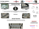
Installing Stringers
STEP 1. Measure the stringer length “S” between
the headers (Figure 18).
STEP 2. Cut a stringer to this length. Use
joist-sized lumber.
STEP 3. If the ceiling joist does not provide one side
of the frame, then cut a second stringer the
same length as the first one. Note that only
one stringer is needed in Figure 18 because
the ceiling joist provides one side of
the frame.
STEP 4. Position the stringer(s) along the unframed
side(s) of your location (Figure 19). Check
that the inside dimensions of the frame are
the same as the rough opening shown on
the box or in Table 2 on page 6.
STEP 5. To attach the stringer(s) to the headers, use
nails that are long enough to go through
both headers and into the stringer at least
one inch. In most cases, a 4 inch nail (20d)
will be long enough. Square the stringer(s)
to the headers at one end and drive 3 nails
through the headers and into the stringer.
Check for squareness, then nail the other
end. Check the rough opening for
squareness by measuring across the
diagonals. The two measurements should
be within 1/8" to be considered square
(Figure 19).
Figure 19
Figure 18
S
Headers
Stringer
Diagonal
Measurements
Headers
Nails

Section 8
INSTALLING TEMPORARY SUPPORT BOARDS
12
STEP 1. Using four nails, attach a 1" x 4" x 36"
board (temporary support board) at the
end of the rough opening where the
hinged end of the access ladder will be.
This temporary support board must form a
3/8" ledge across the rough opening
(Figure 20).
Note: Double-headed nails are
recommended as they are easily removed
when the temporary support boards are
no longer needed.
STEP 2. Using four nails, attach the second
temporary support board to the other end
of the rough opening so that the
temporary support boards are 52-1/2
inches apart (Figure 20).
WARNING: Make sure that the temporary support boards are 52-1/2 inches apart on both sides of
the opening. The access ladder is likely to fall from the ceiling if the temporary support boards are
not properly spaced.
Before Proceeding: You must have a frame of joist-sized lumber the size of the rough opening shown
on the box.
Goal: To install temporary support boards at both ends of the frame that provide ledges large enough to
support the access ladder while still leaving room to open the access ladder.
STEP 1. Insert the pull cord into the hole in the door panel. Tie a knot in the end of the cord to keep the
cord from slipping through the hole when the door is pulled open.If your access ladder box
contained a push/pull down rod and hook assembly instead of a pull cord, follow the supplemental
installation instructions.
STEP 2. One person must go into the overhead space while the other person stays below.
CAUTION: The access ladder cannot be used to climb into or out of the overhead space until it is
permanently nailed to the frame you built AND the access ladder legs have been properly trimmed.
This means that (in some installations) the person in the overhead space must remain there until the
installation is complete.
STEP 3. Make sure that people are kept far enough away from the work area that they will not be hit if the
access ladder is accidentally dropped while being lifted onto the temporary support boards.
STEP 4. Carefully lift the access ladder onto the temporary support boards from below making sure that the
hinged end is in the right place.
First
Temporary
Support
Board
Second
Temporary
Support
Board
Location of
Nails or
Screws
3/8" Ledge at Hinged End
52-1/2"
52-1/2"
Figure 20. View From Below
Section 9
POSITIONING THE ACCESS LADDER
Before Proceeding: You must have temporary support boards at both ends of the frame as shown in
Figure 20.
Goal: To position the access ladder on the temporary support boards in the right direction for use.

(Continued) Section 9
POSITIONING THE ACCESS LADDER
13
STEP 5. After predrilling using 1⁄8" drill bit, nail the hinged end to the header by driving two 16d nails
through the hole in each metal bracket on the headboard (location A at Figure 22).
STEP 6. Open the access ladder door by slowly pulling the cord straight down.
Pulling the cord at angles other than straight down may shift the access ladder off the temporary
support boards and cause it to fall.
Do not push the access ladder open from within the overhead space. The spring tension changes
suddenly—you are likely to lose your balance and fall.
Do not try to force the door open or adjust the temporary support boards while the access ladder is
on them. If the access ladder door is blocked by the temporary support boards, remove the access
ladder and adjust the temporary support boards as needed.
WARNING:
Do not unfold the access ladder legs at this time.
The access ladder is not yet safe to use. Do not
stand on the access ladder or leave it unattended until it is permanently nailed to the frame AND the legs
are properly trimmed. Using the access ladder before the legs are properly trimmed will damage the access
ladder and may cause it to break unexpectedly resulting in serious injury.
Section 10
SHIMMING, SQUARING AND NAILING THE
ACCESS LADDER IN PLACE
Before Proceeding: The access ladder should be positioned on the temporary support boards in the right
direction for use. The access ladder door should be open, but the legs should not be extended.
Goal: To shim the access ladder squarely into the frame you built and then nail it at the proper locations.
WARNING:
The access ladder is not yet safe to use. Do not stand on the access
ladder or leave it unattended until it is permanently nailed to the frame AND
the legs are properly trimmed. Using the access ladder before the legs are
properly trimmed will damage the access ladder and may cause it to break
unexpectedly resulting in serious injury.
STEP 1. Shim the access ladder with wood blocks or tapered
shim stock at the locations shown in Figure 21 until
the access ladder fits squarely in the frame you built.
Tapered shims should be inserted from above and
below (where possible).
NOTICE: Failure to properly square the ladder
frame may result in premature damage to the
closing mechanism.
Check the frame for squareness from above
by measuring across the diagonals (See Fig. 22).
The two measurements should be within 1/8"
to be considered square.
Typical Placement
of Shims
Joist
Frame
Shims
Shims
Stop
Block
Figure 21

(Continued) Section 10
SHIMMING, SQUARING AND NAILING THE
ACCESS LADDER IN PLACE
14
STEP 2. Pre drill all nail locations shown with arrows in
Figure 22 using a 1/8" drill bit. Do not drill into
the joists or headers. Nail the access ladder to the
frame following these instructions.
a. Drive ten 16d nails, checking squareness
and re-shimming as necessary, as shown in
Figure 22. Nails at locations marked “B” must
go through the hole in each of the metal
brackets. Push the ladder up from below until
the hole in the bracket is uncovered, then
drive the nail through the hole. Locations
marked “C” indicate that a nail should be
driven through each wooden “stop block”.
b. Be careful not to hit the springs with the
hammer.
STEP 3. Trim the portion of the shims that stick out above
and below the frame. Shims sticking
out above the frame are a tripping hazard
and must be removed.
A
B
C
Stop
Block
Nail
Location
Diagonal
Measurements
Hinge End
Figure 22
➨
Figure 23
Measure
Distance
D and E
Draw Trim
Line
Mark Distance
D and E
D
E
Note: D will be
shorter than E
D
E
Section 11
TRIMMING THE ACCESS LADDER LEGS
Before Proceeding: You should have the access ladder shimmed and nailed at the proper locations.
Goal: To trim the access ladder legs so that they fit flush with the floor and there are no gaps between the
hinged sections of the access ladder when it is fully extended. It is extremely important that you do not trim
the legs too short!
WARNING:
The access ladder is not yet safe to use. Do not stand on the access ladder or leave it unattended
until it is permanently nailed to the frame AND the legs are properly trimmed. Using the access ladder before
the legs are properly trimmed will damage the access ladder and may cause it to break unexpectedly resulting
in serious injury.
STEP 1. Pull the access ladder door down until it
locks open.
STEP 2. Fold the bottom section of the access ladder
under the middle section. (Figure 23)
STEP 3. With a straight edge, measure distances “D”
and “E” as shown in Figure 23 and record the
measurements in the spaces below. These
distances must be accurately measured to
avoid trimming the legs too short.
NOTE: Measure “D” and “E” from both
side rails of the access ladder—the
ceiling-to-floor height may not be the
same for both sides of the ladder!
Left Rail Right Rail
“D” ___________ ___________
“E” ___________ ___________

STEP 4. Measure down from the top of the lower
section and mark the measurements “D” and
“E” on each side rail. Draw a trim line
connecting the 2 marks (Figure 23). These
trim lines must be drawn accurately to avoid
trimming the legs too short.
STEP 5. If either of the trim lines pass through a metal
washer or any part of a step, remove the step
by unscrewing the metal support rod and
sliding the step out.
STEP 6. Place a support stool under the lower section
of the access ladder and saw off both access
ladder legs along the trim lines—DO NOT
TRIM THE LEGS TOO SHORT! If the access
ladder is used when the legs are too short, it
will be damaged and could break
unexpectedly resulting in serious injury.
STEP 7. Test the trim of the access ladder legs by fully
extending the access ladder for use.
The access ladder should look like Figure 24.
There should be no gaps between the metal
hinges and the feet should be flush with
the floor.
WARNlNG: Gaps between the metal hinges
mean that the feet are not properly trimmed
(Figures 25 and 26). Do not climb the access
ladder if there are gaps between the hinges—
it will be damaged and could break
unexpectedly resulting in serious injury.
If the access ladder looks like Figure 25, then
one or both of the legs are too long. Sand or
trim the feet until there are no gaps between
the hinges and they fit flush with the floor.
If the access ladder looks like Figure 26, then
both of the legs are too short. If there are no
gaps between the hinges but one of the legs is
too short, then the access ladder is not safe to
use. If you have trimmed the legs too short,
do not use the access ladder.
CALL: Werner Ladder Co.
1-724-588-8600
STEP 8. Remove the temporary support boards with a
pry bar or claw hammer.
CONGRATULATIONS!
Your Installation is complete!
(Continued) Section 11
TRIMMING THE ACCESS LADDER LEGS
15
No Gap
No Gap
Feet are flush with floor
Figure 24. Correct Setup
Figure 25. Legs too long
Gap
Feet are not
flush with floor
Gap
Figure 26. Legs too short
Feet are not
flush with floor

16
WERNER LADDER CO., 93 WERNER ROAD, GREENVILLE, PA 16125-9499
Phone: (724) 588-8600
www.wernerladder.com
P/N 52503-01 ©1990/2000 WERNER LADDER CO.
PRINTED IN U.S.A. JULY 1990 R3/00
ATTIC LADDER ACCESSORIES/OPTIONS/REPLACEMENT PARTS
ITEM KIT NO. FITS ON MODEL
PUSH/PULL DOWN ROD
AND HOOK ASSEMBLIES
10-1
10-2
W2208, W2508
W2210, W2510
ATTIC LADDER ASSIST SPRINGS
10-22
10-25
10-30
WH2210
WH2510
WH3010
TRIM KIT 11-1 All Wood Access Ladders
ADJUSTABLE
ALUMINUM RAIL SHOE
21-11
21-12
W2200, W2500
W2500, WH2500, WH300
STEP TRACTION TAPE 39 All Access Ladders
FIRE RETARDANT DOOR Suffix “F”
W2200, W2500, WH2200, WH2500,
WH3000
BIRCH DOOR Suffix “G”
W2200, W2500, WH2200, WH2500,
WH3000
COUNTER BALANCE
MECHANISM KIT
P/N53463 All Folding Access Ladders
SPRING
REPLACEMENT KIT
P/N53465-01
P/N53465-02
P/N53465-03
W2200, W2500, WH2200, WH2500
W2208-48, W2508-48
WH3000
TOTAL OVERHEAD ACCESS
LADDER ASSEMBLY
P/N53481-01
P/N53481-02
P/N53481-03
P/N53481-04
P/N53481-05
P/N53481-06
P/N53481-07
P/N53481-08
P/N53481-13
P/N53481-14
P/N53481-15
P/N53481-16
W2208
W2210
W2508
W2510
WH2208
WH2210
WH2508
WH2510
WH3008
WH3010
W2208-48
W2508-48
LADDER BOTTOM
SECTION ASSEMBLY
P/N53483-01
P/N53483-02
P/N53483-03
P/N53483-04
P/N53483-05
P/N53483-06
P/N53483-07
P/N53483-08
P/N53483-13
P/N53483-14
P/N53483-15
P/N53483-16
W2208
W2210
W2508
W2510
WH2208
WH2210
WH2508
WH2510
WH3008
WH3010
W2208-48
W2508-48
/