Page is loading ...

SL30 SL30W Instructions Rev01
LED LANTERN LIGHT
WITH PIR SENSOR
MODEL: SL30 SL30W
█ INTRODUCTION
The Lantern Light incorporates a PIR (Passive Infra Red) sensing
device which continuously scans a preset operating zone and
immediately switches the light on when it detects movement in that
area. This means that whenever movement is detected within the
range of the sensor the light will switch on automatically to illuminate
pathways, steps, patios, porches, or whatever area you have
selected to light for reasons of safety, convenience or security.
While there is movement within range of the unit the light will remain
on.
█ WHILE TO FIT YOUR SECURITY LIGHT
To achieve best results, we suggest you take into account the
following points:
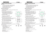
■ Ideally the Lantern Light should be mounted 1.8 to 2.5 meters (6
to 8ft) above the area to be scanned (refer Fig.1A).
■ To avoid damage to unit-do not aim the sensor towards the sun.
■ To avoid nuisance triggering, the sensor should be directed
away from heat sources such as barbecues, Air-conditioners,
other outside lighting, moving cars and flue vents.
■ To avoid nuisance triggering, keeping away from the area of
strong electromagnetic disturbance.
■ Do not aim towards reflective surfaces such as smooth white
walls, swimming pools, etc...
■ The Lantern light scanning specifications (approximately 8
meters at 90°-- round) may vary slightly depending on the
mounting height and location. The detection range of the unit
may also alter with temperature change. Before selecting a
place to install your lantern light you should note that movement
across the scan area is more effective than movement directly
toward or away from the sensor (refer Fig.1B). If movement is
made walking directly towards or away from the sensor and not
across, the apparent detection range will be substantially
reduced. (refer to Fig. 1C)
█ FITTING THE UNIT
Before commencing any electrical work, ensure mains supply
cables are isolated by switching off and removing the relevant
fuse.
1. Installation by a licensed electrician and according to IEC
wiring Regulation.
2. Switch power off at the meter box and ensure that there is
no power to the light.
3. IMPORTANT: DO NOT INVERT THE LANTERN.
4. Un-screw the Screw A and Screw B as the Fig.2(A)
5. Remove the Front Cover (with diffuser), please note: Open
Fig.1(A) Detection Range
2M
2.0 Meters
90¡ ã
8M5M
Fig.1(B) OK Fig.1(C) NOT GOOD
Fig.2(A)
Screw A
Screw B
Front Cover
(with Diffuser)
Mounting
Base
WiringTerminal
Power Cable
UP

SL30 SL30W Instructions Rev01
the Front Cover from the position of Screw A (showed as
Fig.2 (A)).
6. Use the Mounting Base to mark the position of Fixing Wall
Screw holes onto mounting surface. Then drill the wall to depth
of about 4 cm with a no.8 size bit.
7. Pierce the Wiring Rubber and bring Power Cable through.
8. Fit the Mounting Base onto the mounting wall with Fixing
Wall Screws and Plastic Rawl-plugs
9. Connect Power Cable to the Terminal Block
10.
Re-fit the Front Cover onto the Body again
█ TECHNICAL DETAILS :
Voltage: 220-240 V~ 50 Hz
Wattage: 18*0.5W LED
Detection range: 90º (round) and Max. 8 meters
Duration time: 4 ±1minute
Weatherproof: IP44
Detection circuitry: Passive Infra-Red
Due to our policy of continuous improvement we
reserve the right to change specification without prior
notice.
Errors and omissions excepted.
These instructions have been carefully checked prior to
publication. However, no responsibility can be
accepted by Challenger Security Products for any
misinterpretation of these instructions.
CHALLENGER SECURITY PRODUCTS
10 Sandersons Way, Marton,
Blackpool, FY4 4NB
Tel :01253 791888 Fax:01253 791887
Email: enquiries.challenge[email protected]
Website: www.challenger.co.uk
/