Page is loading ...

Y
SI MODEL 95
Y
SI MODEL 95
Y
SI MODEL 95
Y
SI MODEL 95
Handheld
HandheldHandheld
Handheld
Dissolved Oxygen
Dissolved OxygenDissolved Oxygen
Dissolved Oxygen
A
nd
A
nd
A
nd
A
nd
Temperature System
Temperature SystemTemperature System
Temperature System
Operations
Manual


i
CONTENTS
CONTENTSCONTENTS
CONTENTS
SECTION 1 INTRODUCTION .........................................................................................................................................1
SECTION 2 PREPARING THE METER ........................................................................................................................2
2.1 U
NPACKING.................................................................................................................................................................2
2.2 W
ARRANTY CARD ......................................................................................................................................................2
2.3 B
ATTERIES ..................................................................................................................................................................2
2.4 C
ALIBRATION/STORAGE CHAMBER ............................................................................................................................3
2.5 H
AND STRAP...............................................................................................................................................................3
2.6 T
HE METER CASE .......................................................................................................................................................3
SECTION 3 PREPARING THE PROBE.........................................................................................................................4
3.1 C
HOOSING THE RIGHT MEMBRANE CAP.....................................................................................................................4
3.2 M
EMBRANE CAP INSTALLATION.................................................................................................................................4
SECTION 4 OPERATION .................................................................................................................................................6
4.1 T
URNING THE INSTRUMENT ON .................................................................................................................................7
4.2 C
ALIBRATION..............................................................................................................................................................7
4.3 M
AKING MEASUREMENTS ..........................................................................................................................................8
4.4 S
TIRRING.....................................................................................................................................................................9
4.5 S
AVING DATA..............................................................................................................................................................9
4.6 R
ECALLING STORED DATA..........................................................................................................................................9
4.7 E
RASING STORED DATA............................................................................................................................................10
4.8 T
OGGLING BETWEEN %-AIR SATURATION AND MG/L...............................................................................................11
4.9 D
ISSOLVED OXYGEN FILTER.....................................................................................................................................11
4.10 D
ISPLAY BACKLIGHT ..............................................................................................................................................11
SECTION 5 PRINCIPLES OF OPERATION.............................................................................................................12
5.1 MEA C
LARK OXYGEN SENSOR................................................................................................................................12
5.2 DO R
EADINGS FROM THE CATHODE REDUCTION.....................................................................................................13
5.3 F
ORMATION OF AGCL AT THE ANODE ......................................................................................................................13
5.4 F
UNCTION OF THE ELECTROLYTE .............................................................................................................................13
SECTION 6 MAINTENANCE OF THE MEA SENSOR...........................................................................................14
6.1 A
NODE SERVICE........................................................................................................................................................14
6.2 C
ATHODE SERVICE....................................................................................................................................................14
6.3 D
ISSOLVED OXYGEN PROBE PRECAUTIONS .............................................................................................................15
6.4 P
ROBE STORAGE .......................................................................................................................................................15
SECTION 7 DISCUSSION OF MEASUREMENT ERRORS...................................................................................16
SECTION 8 TROUBLESHOOTING............................................................................................................................17
SECTION 9 WARRANTY AND REPAIR...................................................................................................................19
APPENDIX A - GENERAL SPECIFICATIONS..........................................................................................................24
APPENDIX B - REQUIRED NOTICE...........................................................................................................................26
APPENDIX C - ACCESSORIES AND REPLACEMENT PARTS ............................................................................27
APPENDIX D - UNIT CONVERSION...........................................................................................................................28
APPENDIX E - OXYGEN SOLUBILITY TABLE.......................................................................................................29
APPENDIX F - CALIBRATION VALUES TABLE.....................................................................................................31

ii

YSI Incorporated Model 95 1
SECTION 1
SECTION 1SECTION 1
SECTION 1 INTRODUCTION
INTRODUCTIONINTRODUCTION
INTRODUCTION
The YSI Model 95 Handheld Dissolved Oxygen and Temperature System is a rugged, micro-
processor based, digital meter with an attached YSI microelectrode array (MEA) dissolved oxygen
probe. The MEA sensor eliminates the need for stirring in most environmental applications
allowing measurement of DO in the field without an external stirring device. It also reduces
measurement errors caused by insufficient or inconsistent stirring.
The YSI Model 95 has the following features:
• Microprocessor control
• Minimal stirring dependence
• Low maintenance MEA DO probe
• Push-button calibration
• Cap membranes for easy membrane replacement
• Simultaneous display of temperature and DO in % air saturation or mg/L
• Automatic salinity compensation with manual entering of salinity value
• Automatic temperature compensation
• Data storage for 50 sets of readings with on screen recall
• Waterproof case (IP65)
The YSI Model 95 has a non-detachable, combination sensor available with cable lengths of 10, 25,
50 or 100 feet. The Model 95D has a detachable cable. The probe utilizes easy to install cap
membranes and the probe body has been manufactured with stainless steel to add rugged durability
and sinking weight. The silver anode of the MEA DO sensor requires no servicing for up to 10,000
hours (four years) of operation under normal operating conditions (no sulfite contamination).
The Model 95’s micro-processor allows the system to be easily calibrated with the press of a few
buttons. Additionally, the micro-processor performs a self-diagnostic routine each time the
instrument is turned on. The self-diagnostic routine provides useful information about the function
of the instrument and probe. For a list of these diagnostic codes, see Section 8, Troubleshooting.
A probe calibration/storage chamber is built into the instrument case. A small moist sponge in the
chamber provides a water-saturated air environment that is ideal for air calibration of the dissolved
oxygen probe. This chamber also provides a convenient place to store the probe when the system is
not in use. The Model 95 case is waterproof (rated to IP65) allowing operation in the rain without
damage to the instrument.
Six AA-sized alkaline batteries power the Model 95. A new set of alkaline batteries will provide
approximately 150 hours of continuous operation. When batteries need to be replaced, the LCD will
display a “LO BAT” message.
The YSI Model 95 is designed for use in environmental, aquaculture, and industrial applications
where accurate dissolved oxygen and temperature measurements are desired with minimal stirring.

YSI Incorporated Model 95 2
SECTION 2
SECTION 2SECTION 2
SECTION 2 PREPARING THE METER
PREPARING THE METERPREPARING THE METER
PREPARING THE METER
2.1
2.12.1
2.1 UNPACKING
UNPACKINGUNPACKING
UNPACKING
When you unpack your new YSI Model 95 Handheld Dissolved Oxygen and Temperature System
for the first time, compare the packing list with the contents of the shipping box. If there is anything
missing or damaged, call the dealer from whom you purchased the Model 95. If you do not know
which authorized dealers sold the system to you, call YSI Customer Service at 800-765-4974 or
937-767-7241, and we'll be happy to help you.
2.2
2.22.2
2.2 WARRANTY CARD
WARRANTY CARDWARRANTY CARD
WARRANTY CARD
Please complete the Warranty Card and return it to YSI. The warranty card allows the entry of your
purchase of this instrument in our computer system. Once your purchase is recorded, you will
receive prompt, efficient service if any part of your YSI Model 95 needs repair during the warranty
period.
2.3
2.32.3
2.3 BATTERIES
BATTERIESBATTERIES
BATTERIES
There are a few things you must do to prepare your YSI Model 95 for use. First, locate the six AA-
sized alkaline batteries that were included. Use a screwdriver or a small coin to remove the
thumbscrew on the bottom of the instrument (see figure below). This thumbscrew holds the battery-
chamber cover in place. The battery-chamber cover is marked with the words "OPEN" and
"CLOSE."
NOTE: On some models, the battery cover thumbscrew may be unscrewed by hand (a screwdriver
may not be required).
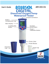
Hand strap
Polarity marking
Thumb screw
Battery chamber
cover
O-rings

Preparing the Meter Section 2
YSI Incorporated Model 95 3
There is a small molded insert inside each of the two battery-chamber sleeves. These labels
illustrate the correct way to install the batteries into each sleeve of the battery-chamber.
CAUTION: It is very important that the batteries be installed ONLY as illustrated. The instrument
will not function and may be damaged if the batteries are installed incorrectly.
Turn the instrument on by pressing and releasing the ON/OFF button on the front of the
instrument. The liquid crystal display (LCD) should come on. Allow a few seconds for the
instrument to complete its diagnostic routine. If the instrument does not operate, consult Section 8,
Troubleshooting.
You may also want to take the instrument into a dark room and with the instrument ON, hold down
the LIGHT button. The instrument back light should illuminate the LCD so that the display can be
easily read.
2.4
2.42.4
2.4 CALIBRATION/STORAGE CHAMBER
CALIBRATION/STORAGE CHAMBERCALIBRATION/STORAGE CHAMBER
CALIBRATION/STORAGE CHAMBER
The Model 95 has a convenient calibration/storage
chamber built into the instrument’s side. This chamber
provides an ideal storage area for the probe during
transport and extended non-use. If you look into the
chamber, you should notice a small round sponge in the
bottom. Carefully put about 10 drops of clean water into
the sponge. Turn the instrument over and allow any
excess water to drain out of the chamber. The wet
sponge creates a 100% water saturated air environment
for the probe that is ideal for dissolved oxygen
calibration.
2.5
2.52.5
2.5 HAND STRAP
HAND STRAPHAND STRAP
HAND STRAP
The hand strap (see figure on previous page) is designed to allow comfortable operation of the
Model 95 with minimum effort. If the hand strap is adjusted correctly, it is unlikely that the
instrument will be easily dropped or bumped from your hand.
To adjust the hand strap on the back of the meter, unsnap the vinyl cover and pull the two Velcro
strips apart. Place your hand between the meter and the strap and adjust the strap length so that your
hand is snugly held in place. Press the two Velcro strips back together and snap the vinyl cover
back into place.
2.6
2.62.6
2.6 METER CASE
METER CASEMETER CASE
METER CASE
The meter case is sealed at the factory and is not intended to be opened, except by authorized
service technicians. Do not attempt to separate the two halves of the meter case as this may
damage the instrument, break the water-proof seal, and may void the manufacturer's
warranty.
Figure 1

YSI Incorporated Model 95 4
SECTION 3
SECTION 3SECTION 3
SECTION 3 PREPARING THE PROBE
PREPARING THE PROBEPREPARING THE PROBE
PREPARING THE PROBE
The YSI Model 95 dissolved oxygen probe is shipped wet with a shipping membrane installed. This
protective membrane cap on the probe tip must be removed and replaced with a new membrane cap
filled with MEA probe solution before using the probe. Follow the instructions below to install the
new membrane cap.
3.1
3.13.1
3.1 CHOOSING THE CORRECT MEMBRANE CAP
CHOOSING THE CORRECT MEMBRANE CAPCHOOSING THE CORRECT MEMBRANE CAP
CHOOSING THE CORRECT MEMBRANE CAP
Two different membrane caps are available for the Model 95. The YSI Model 9501 Membrane Cap
Kit is supplied with the Model 95. This kit contains six 0.5 mil (.0005") membrane caps and a bottle
of MEA probe solution (KCl).
NOTE: YSI 9501 Membrane Caps offer the fastest response to changes in DO and are
recommended by YSI for most applications.
For conditions with low flow or stagnant water, a 1 mil (.001") membrane is available (YSI Model
9502 Membrane Cap Kit). This membrane requires less stirring than the 9501, but has a much
slower response. Use this membrane when minimal stirring (<2"/sec) is available.
3.2
3.23.2
3.2 MEMBRANE CAP INSTALLATION
MEMBRANE CAP INSTALLATIONMEMBRANE CAP INSTALLATION
MEMBRANE CAP INSTALLATION
WARNING: Use only YSI MEA probe solution in the membrane cap. Any other solution will
damage the MEA sensor.
To install a new membrane cap on your YSI Model 95 dissolved oxygen probe:
1. Unscrew and remove the probe sensor guard (see Figure 2 ).
2. Unscrew and remove the old membrane cap.
3. Thoroughly rinse the sensor tip with distilled water.
4. Hold the membrane cap and add 8 to 9 drops of MEA probe solution (about half full).
5. Tap the bottom of the cap with your finger a few times to remove any trapped air bubbles.
CAUTION: Do not touch the membrane surface.
6. Screw the membrane cap onto the probe tightly by hand (to prevent leakage of electrolyte). A
small amount of probe solution should overflow.
7. Shake off any excess probe solution and rinse the stainless steel thoroughly with distilled water
to prevent corrosion.

Preparing the Probe Section 3
YSI Incorporated Model 95 5
WARNING: Use only YSI MEA probe solution in the membrane cap. Any other solution will
damage the MEA sensor.
Figure 2
Unscrew cap
Unscrew guard
Fill new membrane
cap with 8-9 drops
of MEA probe
solution.
Tap cap with finger
to remove bubbles.
Screw guard on
tightly by hand
Screw cap on
tightly by hand

YSI Incorporated Model 95 6
SECTION 4
SECTION 4SECTION 4
SECTION 4 OPERATION
OPERATIONOPERATION
OPERATION
The following diagram is an overview of the operation of the Model 95. See the following sections
for details of operation.
Figure 3

Operation Section 4
YSI Incorporated Model 95 7
4.1
4.14.1
4.1 TURNING THE
TURNING THE TURNING THE
TURNING THE INSTRUMENT ON
INSTRUMENT ONINSTRUMENT ON
INSTRUMENT ON
With the batteries installed correctly, press the ON/OFF button. The instrument will activate all
segments of the display for a few seconds, which will be followed by a self test procedure which
will last for several more seconds. During this power on self test sequence, the instrument’s
microprocessor is verifying that the system is working properly. If the instrument were to detect a
problem, a continuous error message would be displayed. See the section entitled Troubleshooting
for a list of error messages.
NOTE: It is normal for an error to be displayed for a second or two when the system is first
turned on.
4.2
4.24.2
4.2 CALIBRATION
CALIBRATIONCALIBRATION
CALIBRATION
Dissolved oxygen calibration must be done in an environment with a known oxygen content. Since
the amount of oxygen in the atmosphere is known, it makes an excellent environment for calibration
(at 100% relative humidity). The calibration/storage chamber contains a moist sponge to create a
100% water saturated air environment.
Before calibrating the YSI Model 95, complete the procedures discussed in the Preparing the
Meter and Preparing the Probe sections of this manual.
To accurately calibrate the YSI Model 95 you will need to know the following information:
• The approximate altitude of the region in which you are located.
• The approximate salinity of the samples that you will be measuring. Fresh water has a salinity
of approximately zero. Sea water has a salinity of approximately 35 (parts per thousand, ppt). If
you are not certain what the salinity of the sample water is, use a YSI Model 30 Salinity-
Conductivity-Temperature system to determine it.
1. Ensure that the sponge inside the instrument's
calibration chamber is wet. Insert the probe into the
calibration chamber.
2. Turn the instrument on by pressing the ON/OFF
button. Wait for the dissolved oxygen and
temperature readings to stabilize (usually 15
minutes is required after turning the instrument on).
If the instrument was already on, press the MODE
button until dissolved oxygen is displayed in mg/L
or % air saturation. To enter the calibration menu,
use two fingers to press and release both the UP
ARROW and DOWN ARROW buttons at the
same time (DOWN ARROW slightly ahead).
Figure 4

Operation Section 4
YSI Incorporated Model 95 8
3. The LCD will prompt you to enter the local altitude in hundreds of feet. Use the arrow keys to
increase or decrease the altitude. When the proper altitude appears on the LCD, press the
ENTER button once.
EXAMPLE: Entering the number 12 here indicates 1200 feet.
4. The LCD will prompt you to enter the salinity of the sample(s) that you will be measuring. You
can enter any number from 0 to 80 (ppt). Use the arrow keys to increase or decrease the salinity
setting. When the proper salinity appears on the LCD (zero for fresh water), press the ENTER
button.
5. The Model 95 should now display CAL in the lower left of the display, the calibration value
should be displayed in the lower right of the display and the current DO reading (before
calibration) should be on the main display. Make sure that the DO reading (large display) is
stable, then press the ENTER button. The display should read SAVE then should return to the
Normal Operation Mode.
For best results:
• Each time the Model 95 is turned off, re-calibrate before taking measurements.
• Calibrate at a temperature within ±10°C of the sample temperature.
4.3
4.34.3
4.3 MAKING MEASURMENTS
MAKING MEASURMENTSMAKING MEASURMENTS
MAKING MEASURMENTS
The Model 95 has four modes:
Ø Dissolved Oxygen % -- A measurement of oxygen in percent of air saturation (partial
pressure).
Ø Dissolved Oxygen mg/L -- A measurement of oxygen solubility in mg/L.
Ø Recall -- Allows previously stored data to be displayed.
Ø Erase all -- Allows ALL previously stored data to be deleted.
Temperature is displayed in both dissolved oxygen modes.
NOTE: When you turn the Model 95 off, it will “remember” which DO mode you used last and
will return to that mode the next time the instrument is turned on.
To change between the Model 95 modes, simply press and release the MODE button. The Model
95 will cycle through the modes as follows:
Dissolved Oxygen
in % with°C
Dissolved Oxygen
in mg/L with °C
Recall Erase all

Operation Section 4
YSI Incorporated Model 95 9
4.4
4.44.4
4.4 STIRRING
STIRRINGSTIRRING
STIRRING
It is important to realize that even a small amount of stirring will improve the DO and temperature
response times in stagnant water, because the transfer process of heat and oxygen will be facilitated
by convection. Also, the MEA dissolved oxygen probe is not totally stirring independent due to the
consumption of oxygen at the sensor tip during measurement. When taking dissolved oxygen
measurements in totally stagnant samples, the probe must be moved through the sample at a rate of
2 inches per second to provide adequate stirring.
4.5
4.54.5
4.5 S
SS
SAVING DATA
AVING DATAAVING DATA
AVING DATA
The Model 95 is equipped with a non-volatile memory that is capable of storing up to 50 different
sets of readings. Non-volatile means that you do not need to worry that your data will be lost due to
a power failure or interruption, such as when the batteries are removed. Each set consists of
dissolved oxygen in percent, dissolved oxygen in mg/L and temperature. The Model 95 will also
assign a site identity number to each set of readings to allow easy review of the data. This feature is
useful in situations where transcribing data is difficult or not available.
While dissolved oxygen is displayed on the screen (in
% or mg/L), depress the ENTER button and hold it
for approximately 2 seconds. The meter will flash
SAVE on the display along with the current site
identity (1 through 50) being used.
When all 50 sites are full, the display will flash FULL
on the screen. This message will remain on the screen
(even after power down) until a button is pushed.
Once you have acknowledged the memory is full, any
subsequent saved data will begin overwriting existing
data starting with site #1. No additional warning will
be displayed.
4.6
4.64.6
4.6 RECALLING STORED DATA
RECALLING STORED DATARECALLING STORED DATA
RECALLING STORED DATA
1. To put the Model 95 into the RECALL mode,
depress the MODE button repeatedly until “rcl”
is displayed on the screen along with the site ID
number in the lower right corner.
2. Depress the ENTER button to review the last set
of data that was saved. The Model 95 will display
the dissolved oxygen in % air saturation and
temperature. Another press of the ENTER button
will display the dissolved oxygen in mg/L and the
temperature.
3. Depress the UP ARROW button to move up
SAVE
01
rcl
01

Operation Section 4
YSI Incorporated Model 95 10
through the saved sets of data.
4. Depress the DOWN ARROW button to move down through the saved sets of data.
5. When you have finished recalling data, press MODE two times to return to normal operation.
NOTE: The Model 95 will recall data as a list. When the UP ARROW is depressed the Model 95
will display the Site ID# for the previously recorded date. For example: If you are reviewing Site
ID# 5 and the UP ARROW is depressed the Model 95 will display Site ID#4. If you are reviewing
Site ID# 5 and Site ID# 5 was the last set of data stored the DOWN ARROW button will display
Site ID# 1.
Here is an example of the Model 95 memory.
Site ID #1
Site ID #2
Site ID #3 If the UP ARROW button was pressed the Model 95 would display Site ID #2
Site ID #4
Site ID #5
4.7
4.74.7
4.7 ERASING STORED DATA
ERASING STORED DATAERASING STORED DATA
ERASING STORED DATA
1. To erase the data that is stored in the Model 95’s
memory, depress the MODE button until the
Model 95 displays ErAS on the screen.
2. Depress and hold the DOWN ARROW and
ENTER buttons simultaneously for
approximately 5 seconds.
3. When the Model 95 has successfully erased data,
the display reads DONE for 1 to 2 seconds. The
instrument will automatically change to normal
operation after completion and the next saved
data will be stored in site ID# 1.
IMPORTANT: Using the erase function forever and completely erases data in all 50 site
ID’s. Do not use the erase function until all recorded data has been transcribed to an archive outside
the Model 95.
ErAS

Operation Section 4
YSI Incorporated Model 95 11
4.8
4.84.8
4.8 TOGGLING BETWEEN %-AIR SATURATION AND MG/L
TOGGLING BETWEEN %-AIR SATURATION AND MG/LTOGGLING BETWEEN %-AIR SATURATION AND MG/L
TOGGLING BETWEEN %-AIR SATURATION AND MG/L
The UP ARROW key allows quick and convenient switching between the two DO parameters
without going through the instrument’s four modes (using the MODE key). Press the UP ARROW
key to toggle the DO reading between %-air saturation and mg/L.
4.9
4.94.9
4.9 DISSOLVED OXYGEN FILTER
DISSOLVED OXYGEN FILTERDISSOLVED OXYGEN FILTER
DISSOLVED OXYGEN FILTER
The Model 95 is equipped with a DO filter to help filter out instability and high frequency noise.
This feature is useful when measuring dissolved oxygen in an unstable environment such as a fast
moving stream or an aeration tank. The default option for the filter is off. To activate the filter, enter
the filter option menu by pressing both the DOWN ARROW and MODE keys together (Ú key
slightly ahead). Operation procedures:
• Press both the DOWN ARROW and MODE keys
together (Ú
ÚÚ
Ú key slightly ahead). The current status
of the filter is displayed, On or OFF, with a smaller
“FIL” displayed in the bottom right corner of the
screen.
• Press the UP ARROW or DOWN ARROW key to
change the current status of the filter option.
• Press ENTER to confirm the change.
• To abort any changes and exit the filter menu, press
the MODE key (instead of ENTER).
4.10
4.104.10
4.10 DISPLAY BACKLIGHT
DISPLAY BACKLIGHTDISPLAY BACKLIGHT
DISPLAY BACKLIGHT
At times it may be necessary to take measurements with the Model 95 in dark or poorly lit areas. To
help in this situation, the Model 95 comes equipped with a backlight that will illuminate the display
so that it can be easily read. To activate the backlight, press and hold the LIGHT button. The
display will remain lit as long as the button is depressed. When you let it up, the light goes out to
preserve battery life.
On
FIL

YSI Incorporated Model 95 12
SECTION 5
SECTION 5SECTION 5
SECTION 5 PRINCIPLES OF O
PRINCIPLES OF OPRINCIPLES OF O
PRINCIPLES OF OPERATION
PERATIONPERATION
PERATION
5.1
5.15.1
5.1 MEA CLARK OXYGEN SENSOR
MEA CLARK OXYGEN SENSORMEA CLARK OXYGEN SENSOR
MEA CLARK OXYGEN SENSOR
The MEA (microelectrrode array) is a steady-state Clark type polarographic (voltammetric)
dissolved oxygen sensor. The sensor is made of a silver anode and a gold cathode (consisting of 100
very small electrodes, each measuring approximately 8 micrometers in diameter) and is separated
from the measured medium by a semi-permeable Teflon membrane. The small dimensions of each
individual micro surface consume a very small amount of oxygen. Large spacing between adjacent
microsurfaces allows for minimal overlap of diffusion layers from adjacent cathode surfaces. This
design produces the minimal stirring dependence of the MEA probe. The temperature sensing
element (thermistor assembly) is mounted next to the oxygen sensor vertically (see Figure 1),
providing temperature readings for the DO system.
The membrane selectively allows oxygen to permeate into the sensor, but prevents most interfering
molecules and fouling materials from entering. Upon permeating through the membrane, oxygen is
reduced at the gold cathode. The current resulting from this reduction is diffusion-limited and is
proportional to the partial pressure of oxygen in the sample. The counter reaction is the oxidation of
silver at the anode/reference electrode that completes the overall electrolytic reaction in the chloride
medium (KCl electrolyte) behind the membrane. These reactions, at the cathode and the anode, are
as follows:
Cathode reaction: O
2
+ 2H
2
O + 4e
-
==> 4OH
-
Anode reaction: Ag + Cl
-
==> AgCl + e
-
Figure 5
Temperature sensor
Anode (silver)
MEA Cathode (gold)

Principals of Operation Section 5
YSI Incorporated Model 95 13
5.2
5.25.2
5.2 DO READINGS FROM THE CATHODE REDUCTION
DO READINGS FROM THE CATHODE REDUCTIONDO READINGS FROM THE CATHODE REDUCTION
DO READINGS FROM THE CATHODE REDUCTION
The oxygen reduction current is sampled and processed, by the meter, and displayed as either %-air
saturation or mg/L. While the parameter of %-air (partial pressure) is independent of temperature
and salinity, mg/L (solubility of oxygen) is a function of temperature and salinity. The same %-air
reading (same partial pressure) would give a higher mg/L reading at a lower temperature than at a
higher temperature. The higher the salinity, the lower the solubility (mg/L) is for the same %-air
reading at the same temperature.
5.3
5.35.3
5.3 FORMATION OF AgCl AT THE ANODE
FORMATION OF AgCl AT THE ANODEFORMATION OF AgCl AT THE ANODE
FORMATION OF AgCl AT THE ANODE
While the oxygen reduction current passes through the internal circuit to be reported as the DO
reading, it also passes through the anode oxidizing the silver and forming a thin layer of silver
chloride. Furthermore, the oxidation of silver at the chloride medium provides a stable potential that
the cathode potential is referenced to (for instance, the polarization potential of the cathode is -1.0
V versus the potential of the Ag/AgCl redox couple at the silver anode). Since the current of the
MEA sensor is so small, there should not be any significant accumulation of AgCl at the anode for
3 to 4 years.
5.4
5.45.4
5.4 FUNCTION OF THE EL
FUNCTION OF THE ELFUNCTION OF THE EL
FUNCTION OF THE ELECTROLYTE
ECTROLYTEECTROLYTE
ECTROLYTE
There are two main functions for the electrolyte:
1. Supply the chloride (Cl
-
) to the anode/reference electrode for the counter reaction of the
oxygen reduction at the cathode.
2. Provide the ionic conduction of electricity inside the cell, especially in the thin layer
between the gold cathode and the membrane.
Under normal operating conditions, such as measuring oxygen around 100%-air saturation (8.27
mg/L) at 25°C, the electrolyte should last up to 500 hours. This translates into about 62.5 working
days at 8 hours per day operation. The actual electrolyte life, however, may be shorter since, in
most environmental applications, membrane fouling determines the life of the
electrolyte/membrane.

YSI Incorporated Model 95 14
SECTION 6
SECTION 6SECTION 6
SECTION 6 MAINTENANCE OF THE MEA SENSOR
MAINTENANCE OF THE MEA SENSORMAINTENANCE OF THE MEA SENSOR
MAINTENANCE OF THE MEA SENSOR
6.1
6.16.1
6.1 ANODE SERVICE
ANODE SERVICEANODE SERVICE
ANODE SERVICE
Warning: Under no circumstances should ammonium hydroxide be used to clean the silver
anode. Ammonium hydroxide will permanently damage the condition of the MEA surface.
The MEA oxygen sensor is, in principle, the same as the conventional Clark oxygen sensor in that
the sensor is made of a silver anode and a gold cathode, but the cathode is a microelectrode array.
Since the current of the MEA oxygen sensor is so much smaller (on average 100 times smaller) than
the current of YSI conventional oxygen sensors, consumption of the silver anode, due to the
formation of AgCl, is minimal during the lifetime of the probe. There should not be any significant
build-up of silver chloride at the surface of the anode for 3 to 4 years, therefore, the anode should
not require chemical cleaning. However, if the surface of the silver anode has become fouled, gently
wet sand it using 400 grit wet/dry sandpaper, rinse thoroughly with deionized or distilled water and
wipe with a wet paper towel until the dark layer is removed. The directions are as follows:
Anode Cleaning Procedures (See figure 6)
ü Rinse the sensor thoroughly after removing the membrane cap.
ü Use wet 400 grit sandpaper to sand away the top layer of the anode by wrapping the sandpaper
around the anode and gently rotating it until the dark layer is removed.
ü Rinse the anode thoroughly with deionized or distilled water and wipe with a wet paper towel.
ü Rinse the anode again with deionized or distilled water.
Cathode
Anode
Press lightly against
sensor surface
Wet
microcloth
Buffing Tool
Figure 6
6.2
6.26.2
6.2 CATHODE SERVICE
CATHODE SERVICECATHODE SERVICE
CATHODE SERVICE
Warning: Under no circumstances should the gold cathode surface (the MEA surface) be
sanded. Sanding will permanently damage the condition of the MEA surface.
If the MEA oxygen sensor exhibits erratic behavior, such as a current rise at a rate of 1%/hour or
very jumpy readings, it can be serviced by buffing. You can use a few light twists against the
surface with the wet microcloth mounted on the buffing tool provided in the 9503 reconditioning
kit.

Maintenance of the MEA Sensor Section 6
YSI Incorporated Model 95 15
Note: The MEA sensor does not require buffing (cleaning) every time the membrane cap is
changed. Under normal operating conditions, the MEA sensor should be buffed no more than two
times per year.
Cathode Cleaning Procedures
ü Remove the membrane cap and rinse the sensor thoroughly with deionized or distilled water.
ü Place the microcloth on the buffing tool (self-adhesive). Wet the microcloth thoroughly with
deionized or distilled water.
ü Twist the buffing tool back and forth three times in opposite directions while lightly pressing
the buffing tool against the sensor surface (see figure 6).
ü Rinse the sensor surface well with deionized or distilled water after buffing.
6.3
6.36.3
6.3 DISSOLVED OXYGEN PROBE PRECAUTIONS
DISSOLVED OXYGEN PROBE PRECAUTIONSDISSOLVED OXYGEN PROBE PRECAUTIONS
DISSOLVED OXYGEN PROBE PRECAUTIONS
Membrane life depends on usage. If the probe is properly maintained, one membrane cap should
last two to four weeks depending on how often the probe is used and the type of samples measured.
It is recommended that membrane caps not be re-used.
1. To keep the electrolyte from drying out, store the probe in a moist environment, such as the
calibration chamber with the wet sponge inside.
2. Erratic readings are a result of loose, wrinkled, damaged, or fouled membranes, or from large
(more than 1/4 of the circumference of the probe) bubbles in the electrolyte reservoir. If erratic
readings or evidence of membrane damage occurs, you should replace the membrane cap and
the KCl solution. The average replacement interval is two to four weeks.
3. If the membrane is coated with oxygen consuming (e.g. bacteria) or oxygen evolving organisms
(e.g. algae), erroneous readings may occur.
4. Chlorine, sulfur dioxide, nitric oxide, and nitrous oxide can affect readings by behaving like
oxygen at the probe. If you suspect erroneous readings, it may be necessary to determine if
these gases are the cause.
5. Avoid any environment that contains substances that may attack the probe materials. Some of
these substances are concentrated acids, caustics, and strong solvents. The probe materials that
come in contact with the sample include FEP Teflon, stainless steel, epoxy, polyetherimide and
the polyurethane cable covering.
6. Do not allow the probe to strike hard objects. The membrane or sensor inside may be damaged.
6.4
6.46.4
6.4 PROBE STORAGE
PROBE STORAGEPROBE STORAGE
PROBE STORAGE
For long term storage (4 weeks), remove the membrane cap, thoroughly rinse the MEA sensor with
deionized or distilled water and install a new membrane cap filled with MEA probe solution. Store
the sensor in a humid environment such as the calibration chamber with the wet sponge inside. Do
NOT store the probe dry.

YSI Incorporated Model 95 16
SECTION 7 DISCUSSION OF MEASUREMENT ERRORS
SECTION 7 DISCUSSION OF MEASUREMENT ERRORSSECTION 7 DISCUSSION OF MEASUREMENT ERRORS
SECTION 7 DISCUSSION OF MEASUREMENT ERRORS
There are three basic types of dissolved oxygen errors. Type 1 errors are related to limitations of
instrument design and tolerances of instrument components. These are primarily the meter linearity
and the resistor tolerances. Type 2 errors are due to basic probe accuracy tolerances, mainly
background signal, probe linearity, and variations in membrane temperature coefficient. Type 3
errors are related to the operator's ability to determine the conditions at the time of calibration. If
calibration is performed against more accurately known conditions, type 3 errors are appropriately
reduced.
Type 1 Errors
A. Meter linearity error: ±0.5% of full scale reading, or ±0.04 mg/l at 25°C whichever is greater.
B. Component and circuitry error: ±0.04 mg/l
Type 2 Errors
A. DO errors caused by temperature compensation for measurements at ±10°C from calibration
temperature: ±1% of 25° C (±0.08 mg/l)
B. DO errors caused by temperature measurement errors: A maximum ±0.2°C temperature error is
equal to ±0.5% (0.04mg/L at 25°C).
Type 3 Errors
A. Altitude: The maximum DO error caused by calibrating to altitude in increments of 100 feet:
±0.18% (< 0.015 mg/l at 25°C)
B. Humidity: Errors occur if calibration is performed at less than 100% humidity. The worst
possible case would be calibration at 0% humidity. The error varies with the calibration
temperature as follows:
Temperature Calibration Error at 0% humidity
0
o
C 0.09 mg/l
10
o
C 0.14 mg/l
20
o
C 0.21 mg/l
30
o
C 0.33 mg/l
40
o
C 0.50 mg/l
Approximating The Error
It is unlikely that the actual error in any measurement will be the maximum possible error. A better
error approximation is obtained using a root mean squared (r.m.s.) calculation:
r.m.s. error = ±[1a
2
+ 1b
2
+ 2a
2
+ 2b
2
+ 3a
2
+ 3b
2
]
½
mg/l
NOTE: This calculation is for a near extreme set of conditions.
If the probe is calibrated in water-saturated air, then type 3B errors (humidity), the largest error of
all types, is virtually eliminated and the maximum possible error is in the order of 0.1 mg/L for the
case of calibrating around 25°C.
/