Mitsubishi Electric EMU4-PX4/EMU4-AX4 User manual

Type
User manual
Energy Measuring Unit Extension Model for Pulse Input
Energy Measuring Unit Extension Model for Analog Input
MODEL
EMU4-PX4
EMU4-AX4
User’s Manual (Details)
Before operating the instrument, you should first read thoroughly this operation manual for
safe operation and optimized performance of the product.
Deliver this user’s manual to the end user.
1
Safety precautions
Thank you for purchasing the Energy Measuring Unit.
This manual describes setup and usage for the Energy Measuring Unit. Before using the product, please read this manual
carefully to ensure correct use. Especially, in the case of where this unit is to be installed, please read “1. Precautions for Use” to
ensure correct use.
Make sure that the end users read this manual and then keep the manual in a safe place for future reference.
Make sure to deliver this manual to the end-user.
If you are considering using this unit for special purpose such as nuclear power plants, aerospace, medical care or passenger
vehicles please refer to our sales representative.(For details, please see at the end of this manual.)
Notations in this manual
Use the following marks in this manual.
Mark
Meaning of the icons
Danger
Indicates that incorrect handling may result in death or severe injury, ignoring this marking.
Caution
Indicates that incorrect handling may result in injury or property damage, ignoring this marking.
Supplement
Indicates that precautions to avoid a malfunction and to work the unit properly.
Indicates that the pages described that related matters.
Checking package contents
This following items for this device and included in package. Check that no items are missing.
or
Energy Measuring Unit×1
Users Manual (Digest) x1
Related materials
Refer to the following documents as necessary. You can download them from the Mitsubishi FA Global site.
Title
Ref. No.
Energy Measuring Unit EcoMonitorLight/EcoMonitorPlus Series MODBUS I/F Specification
LSPY-9025
Energy Measuring Unit Programming Manual (CC-Link) For ver.1 remote device station
LEN160305
Energy Measuring Unit Programming Manual (CC-Link) For ver.2 remote device station
LEN160316
Energy Measuring Unit Programming Manual (CC-Link IE Field Network Basic) (SLMP)
LEN180123
Trademark
MODBUS is a trademark of Schneider Electric USA Inc.
Other company and product names herein are trademarks or registered trademarks of their respective owners.
In the text, trademark symbols such as "TM" and "®" may not be written.
Feature
(1) Pulse Input Unit
This unit is the option device of Energy Measuring Unit (EcoMonitorPlus.
Extension this unit is capable to measure maximum of four pulse/contact input.
When data exceeded the established upper limit value, indication of LEDs and contact outoput are performed.
(2) Analog Input Unit
This unit is the option device of Energy Measuring Unit (EcoMonitorPlus.
Extension this unit is capable to measure maximum of four analog inputs.
When data exceeded the set upper limit value, indication of LEDs and contact outoput are performed.
2
Table of Content
Safety precautions ........................................................................................................................................................ 1
Feature ............................................................................................................................................................................. 1
Table of Content ............................................................................................................................................................. 2
1. Precautions for Use .................................................................................................................................................. 3
1.1 Precautions for Operating Environment and Conditions ....................................................................................... 3
1.2 Matters concerning the precaution before use ....................................................................................................... 3
1.3 Installation and Wiring Precautions ......................................................................................................................... 3
1.4 Precautions for Use ................................................................................................................................................. 5
1.5 Maintenance Precautions ........................................................................................................................................ 5
1.6 Storage Precautions ................................................................................................................................................ 5
1.7 Disposal Precautions ............................................................................................................................................... 5
1.8 About packaging materials and this manual .......................................................................................................... 5
2. Disclaimer ................................................................................................................................................................. 6
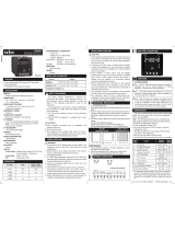
3. Name and function of each part ............................................................................................................................ 6
3.1 Name of each part ................................................................................................................................................... 6
3.2 Indication and function of LEDs .............................................................................................................................. 7
4. Attaching and removing the unit........................................................................................................................... 8
4.1 How extension to measure unit ............................................................................................................................ 8
4.2 Mounting on IEC rail .............................................................................................................................................. 8
4.3 Mounting on JIS agreement type attachment...................................................................................................... 8
5. Procedure for wiring ................................................................................................................................................ 9
5.1 Wiring for EMU4-PX4 ............................................................................................................................................ 9
5.2 Wiring for EMU4-AX4 .......................................................................................................................................... 10
5.3 Precautions for the connection wire ...................................................................................................................... 11
6. Setting ..................................................................................................................................................................... 12
6.1 Setting data ............................................................................................................................................................ 12
6.2 Initialization of related item by changing the setup ............................................................................................ 14
7. Operation ............................................................................................................................................................... 16
7.1 Measurement ......................................................................................................................................................... 16
7.2 Upper/lower limit monitoring function .................................................................................................................. 18
8. Device operation ...................................................................................................................................................... 21
8.1 Pulse Input Unit(EMU4-PX4) ................................................................................................................................ 21
8.2 Analog Input Unit(EMU4-AX4) .............................................................................................................................. 22
9. Reference ............................................................................................................................................................... 24
9.1 In case you think the unit is in failure .................................................................................................................... 24
9.2 After-sales service .................................................................................................................................................. 24
9.3 Q&A ........................................................................................................................................................................ 25
10. Requirement for the compliance with EMC Directives EMC ......................................................................... 26
11. Specifications ...................................................................................................................................................... 27
12. External dimensions .......................................................................................................................................... 28
13. Index ................................................................................................................................................................... 29
3
1. Precautions for Use
1.1 Precautions for Operating Environment and Conditions
This unit is premised on being used in pollution degree 2 (Note 1) environment. When used in higher pollution degree, protect
this unit from pollution on another device side to be incorporated.
This unit is used in combination energy measuring unit (EMU4-BM1-MB, EMU4-HM1-MB, EMU4-LG1-MB or EMU4-CNT-MB),
energy measuring unit expansion product for electric energy monitoring (EMU4-A2 or EMU4-VA2). Over voltage category of
measuring circuit in conbination unit is CAT III (Note 1).
Do not use this product in the places listed below. Failure to follow the instruction may cause malfunctions and a life decrease of
product.
Places the Ambient temperature exceeds the range -5 - +55°C.
Places the average daily temperature exceeds 35°C.
Places the Relative humidity exceeds the range 30-85% or places
with dewfall.
Vibration and impact exceed the specifications.
Dust, corrosive gas, saline and oil smoke exist.
Places exposed to direct sunlight.
Places exposed to rain or water drop.
Places in strong electromagnetic field or places large
amounts of external noise exist.
Places metal fragments or conductive substances are flying.
Altitude exceeds 2000m.
Note 1: For the definition of the pollution degree and the over voltage category, refer to EN61010-1/2010.
1.2 Matters concerning the precaution before use
Use the unit in the specified usage environment and conditions.
To set this unit, dedicated energy measuring unit (EMU4-BM1-MB, EMU4-HM1-MB, EMU4-LG1-MB or EMU4-CNT-MB)
is necessary. For the setting method, refer to Users manual (Details) of the energy measuring unit.
To set this unit, dedicated small-size display unit (EMU4-D65) is necessary. For the setting method, refer to User’s manual
(Details) of the display unit.
1.3 Installation and Wiring Precautions
Danger
Shut off the external power supply for the unit in all phases before installing or wiring. Failure to do
so may cause an electric shock or damage of this unit.
Work under the electric outage condition when installing and wiring. Failure to do so may cause
electric shock, a failure of the unit, a fire etc.
Caution
<Precautions for Electric work>
Any person who is involved in the installation and the wiring of this unit should be fully competent to do this work.
Keep the space around this product (all directions except the back) is 30 mm or more (100 mm or more for UL
standard compliance).
When tapping or wiring, take care not to entering any foreign objects such as chips and wire pieces into this unit.
Check the connection diagram when wiring. Wrong wiring may cause failure of the unit, a fire or electric shock.
For protection against noise, transmission lines and input/output lines shall not be placed close to or bound
together with the power lines and high-voltage lines.
The wires to be connected to this unit shall be placed in a duct or fixed together by cramping. If the electric wires are
not placed in the duct or cramped together, loosen wires or their movement or careless stretch may cause a breakage
of the unit or wire or a malfunction due to poor contact of electric wires.
If transmission lines and input/output lines are placed close to or bound together with the power lines and high-voltage
lines, keep distance as below between them.(Except for the input side of terminal block) If there is concern about the
influence of noise even if the distance is as follows, we recommend using a shielded cable.
Condition
Distance
Power line 600V or less
300mm or longer
Other power line
600mm or longer
4
<Connection of terminal block>
Strip the wires with proper length. Overlong stripping length may cause short to next wire. Shorter stripping length may
cause contact failure.
Take care not to short to next terminal by a filament. (Do not plate the wires with solder.)
Do not connect three or more wires to one terminal of a terminal block for preventing loose contact and wires dropout.
Use appropriate size of electric wires. If inappropriate size of electric wire is used, it may cause a fire due to generated
heat.
Tighten the screw within the specified torque. Under tightening can cause drop of the screw, short circuit or malfunction.
Over tightening can damage the screw and/or unit, resulting in drop, short circuit or malfunction.
After tightening the screws, be sure to check all the screws tightened. Loose screw may cause malfunction of the unit, a
fire or electric shock.
Be sure to attach the terminal cover to prevent electric shock.
Use the crimp-type terminal appropriated for the size of electric wires. If inappropriate crimp-type terminal is used, a wire
breakage or a contact failure may occur, which may cause a device malfunction, a failure, a burnout or a fire.
Frame GND terminal must be grounded according to the D-type ground (ground resistance is not exceed 100Ω).
Do not directly touch any conductive part of the unit. Doing so can cause electric shock, failure or malfunction of the unit.
Do not input voltage and current at NC terminals. Doing so can cause failure or malfunction of the unit.
<Connection with the current sensor>
When using this product, make sure to use it in combination with current sensor (EMU-CT**, EMU-CT**-A. EMU2-CT5
and EMU2-CT5-4W). This product cannot connect with the secondary side (5A) of current transformer. Please
not to exceed the rating of this product for input of current sensor. For further details, please refer to current sensor
manual to maintain the functionality and the accuracy of this product.
The dedicated current sensor (EMU-CT**, EMU-CT**-A) is used only for low voltage circuit. It cannot be used for a high
voltage circuit. EMU2-CT5 and CT5-4W should be used with the secondary side (5A) of transformer transfixed. If it is
connected with a high-voltage circuit by mistake, it may cause a burnout of the device and a fire. It is critically dangerous.
For the allowable maximum voltage of current sensor, refer to instruction manual (detail) of Energy Measuring Unit
(EMU-BM1-MB, EMU4-HM1-MB)
The dedicated current sensor has a polarity (directionality). Be careful about it when installing the unit.
If the wires connected to this unit are strongly pulled off, it may cause a malfunction or a breakage to the unit or the wire.
<Connection of frame GND terminal>
Do not exceed the specified voltage when doing an insulation resistance test and a commercial frequency withstand
voltage test.
Frame FG terminal must be grounded according to the D-type ground.
To prevent persons with little knowledge about electric equipment from electric shock, panel must be taken either following
measure.
Lock the panel so that only those who get an education about electric equipment and have sufficient knowledge can unlock,
or shut off power supply automatically by opening the panel.
Cover the dangerous part of this unit.
5
1.4 Precautions for Use
Before operating the product, check that active bare wire and so on does not exist around the product. If any bare wire
exists, stop the operation immediately, and take an appropriate action such as isolation protection.
In the event of a power outage during the setting by Display unit / Communication line, the Energy Measuring unit is not set
correctly. Please set again after power recovery.
When use Energy Measuring Unit Analog Input Model (ModelEMU4-AX4)/ Energy Measuring Unit Pulse Input Model
(ModelEMU4-PX4) with Option units(ModelEMU4-CM-C, EMU4-LM), number of connectable show in the tables below.
How to check the version Number of connectable
19R004
316 A 0066o
Version
non-connected EMU4-CM-C EMU4-LM
A
3 units 2 units 3 units
later B
3 units 3 units 3 units
Number of connectable
Version
Caution
Do not disassemble or modify this unit. It may cause failure, malfunction, injury or fire.
Use this unit within the ratings specified in this manual. If it is used outside the ratings, it may cause not only malfunction
or failure but also fire burnout.
1.5 Maintenance Precautions
Use a soft dry cloth to clean off dirt of the unit surface. Do not let a chemical cloth remain on the surface for an extended
period of time nor wipe the surface with thinner or benzene.
Check for the following items to use this unit properly for long time.
(1) Daily maintenance
(a) No damage on this unit
(b) No abnormality with LCD indicators
(c) No abnormal noise, smell or heat
(2) Periodical maintenance (Once every 6 months to 1 year)
- No looseness with installation and wire connection
Caution
Do periodical maintenance under the electric outage condition. Failure to do so may cause electric shock,
failure of the unit or a fire. Tighten the terminal regularly to prevent a fire.
1.6 Storage Precautions
To store this unit, turn off the power and remove wires, and put it in a plastic bag.
For long-time storage, avoid the following places. Failure to follow the instruction may cause a failure and reduced life of the
unit.
- Places the Ambient temperature exceeds the range -10 - +60°C.
- Places the average daily temperature exceeds 35°C.
- Places the Relative humidity exceeds the range 30-85% or places with dewfall.
- Vibration and impact exceed the specifications.
- Dust, corrosive gas, saline and oil smoke exist.
- Places metal fragments or conductive substances are flying.
- Places exposed to rain or water drop.
1.7 Disposal Precautions
When disposing of this unit, treat it as industrial waste.
1.8 About packaging materials and this manual
For reduction of environment load, packaging materials are produced with cardboard, and this manual is printed on recycled
paper.
6
2. Disclaimer
It is prohibited to reprint or copy all contents of this document in any form without our permission.
The contents of this document will be updated to follow revisions to software and hardware, however under unavoidable
circumstances it may not be synchronized.
3. Name and function of each part
3.1 Name of each part
(1)EMU4-PX4 (2)EMU4-AX4
(3)Back view and side view
Connector (female)
Connect to
extension units.
Connection stop
This is used to
connect the extension
unit.
Right side
IEC rail fixture
LED
Operation mode is
displayed.
(Please reference to 4.2
LED display and function)
External input terminals X1X4, COMX1COMX4
Connect to pulse / contact input.
External output terminals
Y1, COMY1
Connect to external output.
Connector (male)
Connect to the energy
measuring unit.
Analog input terminals AX1AX4, COMAX1COMAX4
Connect to analog input.
Frame GND
FG
Connect to ground (D type
ground)
External output terminals
Y1, COMY1
Connect to external output.
LED
Operation mode is
displayed.
(Please reference to 4.2
LED display and function)
Connector (male)
Connect to the energy
measuring unit.
Back view
7
3.2 Indication and function of LEDs
The names and operations of LEDs are as follows.
(1) EMU4-PX4
Name
Color
Function
Status
RUN LED
Red
Indicate operating status of this unit.
ON: Normal operation
OFF: Power off or hardware failure
*1
X1 LED
Red
Indicate measuring status of this circuit X1.
ON: Contact state is ON
Blink: In the middle of measuring the
pulse
OFF: Other
ALM X1 LED
Red
Indicate occurance status of upper limit alert of the
circuit X1.
ON: An error occurs
*1
Blink
*2
: Upper limit alert is issued
OFF: No alert
X2 LED
Red
Indicate measuring status of this circuit X2.
ON: Contact state is ON
Blink: In the middle of measuring the
pulse
OFF: Other
ALM X2 LED
Red
Indicate occurance status of upper limit alert of the
circuit X2.
ON: An error occurs
*1
Blink
*2
: Upper limit alert is issued
OFF: No alert
X3 LED
Red
Indicate measuring status of this circuit X3.
ON: Contact state is ON
Blink: In the middle of measuring the
pulse
OFF: Other
ALM X3 LED
Red
Indicate occurance status of upper limit alert of the
circuit X3.
ON: An error occurs
*1
Blink
*2
: Upper limit alert is issued
OFF: No alert
X4 LED
Red
Indicate measuring status of this circuit X4.
ON: Contact state is ON
Blink: In the middle of measuring the
pulse
OFF: Other
ALM X4 LED
Red
Indicate occurance status of upper limit alert of the
circuit X4.
ON: An error occurs
*1
Blink
*2
: Upper limit alert is issued
OFF: No alert
(2) EMU4-AX4
Name
Color
Function
Status
RUN LED
Red
Indicate operating status of this unit.
ON: Normal operation
OFF: Power off or hardware failure
*1
MEA. AX1 LED
Red
Indicate measuring status of this circuit AX1.
ON: In the middle of measuring
OFF: Other
ALM. AX1 LED
Red
Indicate occurance status of upper limit alert of the
circuit AX1.
ON: An error occurs
*1
Blink
*2
: Upper/lower limit alert is issued
OFF: No alert
MEA. AX2 LED
Red
Indicate measuring status of this circuit AX2.
ON: In the middle of measuring
OFF: Other
ALM. AX2 LED
Red
Indicate occurance status of upper limit alert of the
circuit AX2.
ON: An error occurs
*1
Blink
*2
: Upper/lower limit alert is issued
OFF: No alert
MEA. AX3 LED
Red
Indicate measuring status of this circuit AX3.
ON: In the middle of measuring
OFF: Other
ALM. AX3 LED
Red
Indicate occurance status of upper limit alert of the
circuit AX3.
ON: An error occurs
*1
Blink
*2
: Upper/lower limit alert is issued
OFF: No alert
MEA. AX4 LED
Red
Indicate measuring status of this circuit AX4.
ON: In the middle of measuring
OFF: Other
ALM. AX4 LED
Red
Indicate occurance status of upper limit alert of the
circuit AX4.
ON: An error occurs
*1
Blink
*2
: Upper/lower limit alert is issued
OFF: No alert
*1Reference to 9.1 In case you think the unit is in failure.
*2Repeat 500msec lighting and 500msec extinction.
8
4. Attaching and removing the unit
Caution
Any person who is involved in the installation and the wiring of this unit should be fully competent to do this work.
4.1 How extension to measure unit
EMU4-BM1-MB, EMU4-HM1-MB, EMU4-LG1-MB, EMU4-CNT-MB are the connectable unit.
The number of extension units that can be connected to one base unit depends on the connection the
product version and the CC-Link communication unit of the base unit.( 1.4 Precautions for Use)
Caution
Do not disassemble or modify this unit. It may cause failure, malfunction, injury or fire.
4.2 Mounting on IEC rail
4.3 Mounting on JIS agreement type attachment
Peel off the label pasted right part of
measure unit.
Rock the measure unit to slide consolidated
claws (groon).
Blank label
Plug connector (male) to connector (female)
of measure unit for brought into close
contact.
Applicable IEC rail
(35mm)
Mounting
Removing
(1) Pull IEC rail fixture downward
(2) Pull the unit
(1) Hold the unit and pull IEC
rail fixture downward
IEC rail
(4) Push the IEC rail
fixture upward
(3) Push in
(2) Catch
7.3 or more
Mounting
JIS agreement type
attachment
Removing
Spring fitting
Attachment
panel
Hook
(2) Hitch 3 chases at
upper part of the
module to the
hook on the
attachment plate.
(3) Push the module down and fit in the
spring fitting in chases at the lower
part of the module.
(1) Push the stopper of the IEC rail above.
(1) Push down the
spring fitting.
(2) Lift the lower part of
module slowly and
remove in reverse order
of Attaching.
9
5. Procedure for wiring
Follow the wiring example for external connections of this unit.
5.1 Wiring for EMU4-PX4
Structure
Unit
Model
Measure unit Energy Measuring High Performance Model EMU4-HM1-MB
Extension unit 1 Extension Model for Pulse Input EMU4-PX4
Extension unit 2 - -
Extension unit 3 - -
External output 1
External input 1
External output 1
External input 1
X1(+) COMX1(-)
Input the
measuring
circuit voltage
Fuse 0.5A
External input 2
X2(+) COMX2(-)
External input 3
X3(+) COMX3(-)
External input 4
X4(+) COMX4(-)
RS485 (MODBUS
RTU)
Input the
measuring
circuit current
(3P4W)
EMU4-PX4
EMU4-HM1-MB
10
5.2 Wiring for EMU4-AX4
Structure
Unit
Model
Measure unit Energy Measuring High Performance Model EMU4-BM1-MB
Extension unit 1 Extension Model for Same Voltage System EMU4-A2
Extension unit 2 Extension Model for Different Voltage System EMU4-VA2
Extension unit 3 Extension Model for Analog Input EMU4-AX4
EMU4-VA2
EMU4-A2
EMU4-BM1-MB
RS485(MODBUS RTU)
External
output 1
Analog input 1
AX1(+) COMAX1(-)
Input the
measuring
circuit voltage
Input the
measure circuit
current
(1P3W, 3P3W)
EMU4-AX4
Input the
measure
circuit current
(1P2W)
External
output 2
External
output 1
External
output 2
External
output 1
Fuse 0.5A
Analog input 2
AX2(+) COMAX2(-)
Analog input 3
AX3(+) COMAX3(-)
Analog input 4
AX4(+) COMAX4(-)
Input the
measure
circuit current
(1P2W)
Input the
measure
circuit current
11
5.3 Precautions for the connection wire
For MODBUS
communication wiring, recommended to have the extra length wires about 200mm (When extended to B /
NET transmission from MODBUS
communication, use of MODBUS
communication wiring is possible).
External input / Analog input terminals has polarity. Please do not mistake the connection. Xn/AXn terminals is anode, and
COMXn/COMAXn is cathode. (n = 1~4)
In unused channels, if the circuit between two terminals is kept open, an undefined digital value may be output.
To prevent this phenomenon, set the AD conversion enable or disable setting (AD CONV.) in the unused channel to disable.
The default of setting is enable. Refer to Users manual (Details)Chapter 6.1 Setting data”.
5.3.1 How to connect wire
<External input/output terminals>
Use appropriate crimp-type terminal. Applicable crimp-type terminal is shown in the tables below.
Use electric wires as below, and tighten the terminal screws by the torque as below.
EMU4-PX4/EMU4-AX4
Applicable wire
Tightening torque
Applicable crimp-type terminal
External input terminals
Stranded wire: AWG22-16
(0.3mm
2
1.3mm
2
)
Single wire: AWG22-16
(φ0.65mm -φ1.25mm)
0.5 - 0.6 N·m
For M3 screw of external
diameter below 6.1mm
Analog input terminals
Applicable wire
Tightening torque
Applicable crimp-type terminal
Contact output terminals
Stranded wire: AWG26-18
(0.12mm
2
- 0.8mm
2
)
Single wire: AWG26-18
(φ0.4mm -φ1.0mm)
0.5 - 0.6 N·m
For M3 screw of external
diameter below 6.1mm
FG terminals (EMU4-AX4 only)
5.3.2 Connection of external output
In case using external output, refer to the following.
External output: For the case of contact output
Wiring length of pulse input (Reference value)
The wire length for each wire diameter is below. Please refer to wiring.
Polyethylene insulating vinyl sheath cable FCPEV wire.
Wire diameter [mm]
Resistivity[Ω/km]
Wiring length[m]
0.5
94
300
0.65
56.8
400
0.9
29.2
750
1.2
16.5
1000
Cautions
For protection against noise, transmission lines and input/output lines shall not be placed close to or bound
together with the power lines and high-voltage lines. Keep distance as below between them. (except for the
terminal block)
If there is concern about the influence of noise even if the distance is as follows, we
recommend using a shielded cable.
Condition
Distance
High-voltage line 600V or less
300mm or more
Other high-voltage line
600mm or more
For the actual usage, connect the FG terminal to ground. (D-type ground: Type 3) Connect it directly to the
ground terminal.
Do not connect to FG terminal during the insulation resistance test and pressure test. Refer to “User’s
manual (Details)” Chapter 11 “Specifications” for the applying place.
No-voltage a-contact
DC 35V 75mA or,
AC 24V 75mA (power factor : 1)
リレー
Relay
12
6. Setting
6.1 Setting data
To set this unit, dedicated small-size display unit (EMU4-D65) is necessary.
For the setting method, refer to User’s manual (Details) of the display unit.
The data can be setup is shown below.
The underline means the default of setting.
Setting item Setting value Details
Correspondence of models
EMU4-PX4
EMU4-AX4
Input
Non, Contact, Pulse
Set the measurement type of external input.
It can be set for each CH.
-
CONV.Rate
0.001 ~ 10000 (1.000)
Set the conversion rate per pulse for conversion
from pulse to other units, when input setting
value is Pulse.
It can be set for each CH.
-
Unit
Non, Wh, kWh, MWh, J,
m
2
,m
3
, L, kL, sec, min,
hour, piece, set, g, kg, t,
¥, $
Set the unit of pulse conversion, when input
setting value is Pulse.
It can be set for each CH.
-
Input Reset
Mode
Auto, Hold
Set the reset method of contact state, when
input setting value is contact.
It can be set for each CH.
(For details, refer to 8.1.3 Contact state.)
-
O P. Ti me
Off, On
Set the enable or disable the measuring
operation time, when input setting value is
contact.
It can be set for each CH.
-
MEA.Mode
50ms SAMP. ,
1ms SAMP.
Set the measuring interval.
-
AD CONV.
Off,On
Set the enable or disable the AD conversion.
If AD converted is off, do not measuring AD
conversion value and scaling value.
It can be set for each CH.
-
Range
Current, Voltage
Set the analog input range to current input or
voltage input, when AD CONV. setting value is
on.
It can be set for each CH.
-
Moving average
001 ~ 100(1)
Set the number of times to perform the moving
average of AD conversion, when AD CONV.
setting value is on.
It can be set for each CH.
(For details, refer to 8.2.3 Number of times
exceeding the Limit.)
-
Scaling Upp.
-32767 ~ 32767
(04095)
Set the upper range of scaling value.
It can be set for each CH, when AD CONV.
setting value is on.
Example 1 In the case of Range=Current,
Analog input=20mA, Scaling Upp /
Low=4095/0
Scaling value=-4095
Example 2 In the case of Range=Current,
Analog Input=20mA, Scaling Upp /
Low=0/4095
Scaling value=0
-
Scaling Low.
-32767 ~ 32767 (0)
-
13
Setting item Setting value Details
Correspondence of models
EMU4-PX4
EMU4-AX4
Scaling Unit
Non, A, mA, kA, V, kV,
W, kW, MW, Hz, N, kN,
Pa, kPa, MPa, C, deg, %
Set the unit of scaling value, when AD CONV.
setting value is on.
It can be set for each CH.
-
Limit
Scaling Low. ~ Scaling
Upp. (Scaling Low.
*1
)
Set the any value to measuring the number of
times exceeding the limit.
Number of times exceeding the limit is
measuring the number of times scaling value
exceeding the any value.
(For details, refer to 8.2.3 Number of times
exceeding the Limit.)
-
Factor
x1, x10, x100, x1000
Set the monitoring factor for number of times
exceeding the limit.
It can be set for each CH.
Output
Non, Alarm, Contact
To set the output type of contact output
terminals.
AlarmContact is output when an alarm occurs.
Contact
It is possible to control the contact in
communications.
Alarm
EMU4-PX4:
Off, On
EMU4-AX4:
Non, Upp., Low.,
Upp. & Low.
Set the enable or disable the alarm.
If the unit is EMU4-PX4, monitoring type is only
upper limit.
It can be set for each CH.
(For details, refer to 7.2 Upper/lower limit
monitoring function.)
Alarm target CH
Non, CH1, CH2, CH3,
CH4
Set the CH to output the alarm state from
contact output terminals.
PLS.Upp.
0.001 ~ 999999000
(100000)
Set the upper limit alarm value of pulse
conversion.
It can be set for each CH.
-
Scaling alarm
value Upp.
Scaling Low. ~ Scaling
Upp. (Scaling Upp.
*2
)
Set the upper limit alarm value of scaling value.
It can be set for each CH.
Can not set a value less than Scaling alarm
value Low.
-
Scaling alarm
value Low.
Scaling Low. ~ Scaling
Upp. (Scaling Low.
*1
)
Set the lower limit alarm value of scaling value.
It can be set for each CH.
Can not set a value larger than Scaling alarm
value Upp.
-
Delay
0sec, 5sec, 10sec,
20sec, 30sec, 40sec,
50sec, 1min, 2min, 3min,
4min, 5min
Set the time to detect the alarm.
It can be set for each CH.
(For details, refer to 7.2 Upper/lower limit
monitoring function.)
-
Alarm Reset
Mode
Auto, Hold
Set the reset method of alarm state.
It can be set for each CH.
(For details, refer to 7.2 Upper/lower limit
monitoring function.)
-
*1If you set Scaling Upp. < Scaling Low., the default is Scaling Upp..
*2If you set Scaling Upp. < Scaling Low., the default is Scaling Low..
14
6.2 Initialization of related item by changing the setup
Setup value and measured data is initialized after change the setup value according to table 6.2.1, 6.2.2, 6.2.3 and 6.2.4.
Please setup again.
Table 6.2.1 List of initialization when changing setup value (setup data) (EMU4-PX4)
Unit
Alarm target CH
Setup items
Input
CONV.Rate
Input Reset Mode
Output
Ala rm
PLS.Upp
Alarm target CH
OP.Time
Setup value to be changed
Setup value(initialized)
Alarm
PLS.Upp
Input
Input Reset Mode
Output
OP.Time
CONV.Rate
Unit
Initializes the settings of CH that have vhanged the settings.
Table 6.2.2 List of initialization when changing setup value (Measured data and operating data) (EMU4-PX4)
Pulse count
Pulse convertion
Operating time
Alarm target CH
Setup items
Input
CONV.Rate
Unit
Input Reset Mode
Output
Alarm
PLS.Upp
OP.Time
Setup value to be changed
Measured value
(initialized)
Integral value
Initializes the settings of CH that have vhanged the settings.
15
Table 6.2.3 List of initialization when changing setup value (setup data) (EMU4-AX4)
Range
Delay
Factor
Scaling Low
Output
Ala rm
Scaling alarm value Upp
Limit D
Alarm Reset Mode
Alarm target CH
Setup items
Scaling Low
Output
MEA.Mod e
AD CONV.
Moving average
MEA.Mode
AD CONV.
Scaling alarm value Low
Scaling Upp
Limit A
Limit B
Range
Moving average
Scaling Upp
Limit C
Alarm
Scaling alarm value Upp
Scaling alarm value Low
Delay
Alarm Reset Mode
Alarm target CH
Limit A
Limit B
Limit C
Limit D
Factor
Setup value(initialized)
Setup value to be changed
Scaling Unit
Scaling Unit
Initializes the settings of CH that have vhanged the settings.
Table 6.2.4 List of initialization when changing setup value
(Measured data and number of times exceeding the limit data) (EMU4-AX4)
AD conversion level
Scaling level
AD conversion level
Scaling level
Limit A
Limit B
Limit C
Limit D
Limit C
Limit D
Factor
Scaling Upp
Scaling Low
Output
Alarm
Scaling alarm value Upp
Scaling alarm value Low
AD CONV.
Range
Max
Min
Number of
times
exceeding
the Limit
Measured value(initialized)
Setup value to be changed
Scaling Unit
Moving average
Delay
Alarm Reset Mode
Alarm target CH
Limit A
Limit B
Setup items
MEA.Mode
Initializes the settings of CH that have vhanged the settings.
16
7. Operation
7.1 Measurement
Measurement elements are showed below table in each unit.
Please setting below for measurement.
… Measured elements
Measuring elements
Setup items
EMU4-PX4
EMU4-AX4
Pulse count
Input
-
Pulse conversion
Input, CONV.Rate
-
Contact state
Input, Input Reset Mode
-
Operating time
Input, OP.Time
-
AD conversion value
*1
AD CONV., Range
-
Scaling value
AD CONV., Range, Scaling Upp,
Scaling Low
-
Number of times
exceeding the Limit
Limit
*2
-
*1Can not be displayed in display unitcan get in communication.
*2Please set only the items necessary in LevelALevelD.
The measurement elements that can be monitored by the display unit, some communication and logging units are shown below.
In the case displaying in Display unit.
Displayed items
EMU4-PX4 EMU4-AX4
Pulse count
Present
Pulase converted
Present
Operating time
Present
Contact input state
Present
AD coverted value
Present
Max, Min
Scaling value
Present
Max, Min
Number of times exceeding the Limit
Present
Time
Present
1
1
Error
Measured data
Not measured data
17
In the case monitoring with various communications
The supported communications are as follows.
• CC-Link communication
• CC-Link IE Field Basic communication
• SLMP communication
• MODBUS communication
Monitored items
EMU4-PX4 EMU4-AX4
Pulse count
Present
Pulase converted
Present
Operating time
Present
Contact input state
Present
AD coverted value
Present
Max, Min
Scaling value
Present
Max, Min
Number of times exceeding the Limit
Present
Time
Present
Error
Monitorable data
Monitorable data only MODBUS
Not monitorable data
In the case logging using EMU4-LM
Monitored items
EMU4-PX4 EMU4-AX4
Pulse count
Present
Pulase converted
Present
Operating time
Present
Contact input state
Present
AD coverted value
Present
Max, Min
Scaling value
Present
Max, Min
Number of times exceeding the Limit
Present
Loggable data
Not loggable data
18
7.2 Upper/lower limit monitoring function
7.2.1 How to use upper/lower limit alarm function
This device can set the upper/lower limit alarm value for each measured value individually.
< Monitoring items >
EMU4-PX4
EMU4-AX4
Upper limit item
Pulse conversion
Scaling value
Lower limit item
-
Scaling value
< Alarm setting >
EMU4-PX4 and EMU4-AX4
Upper limit value…….. Set the upper limit of measured value. For setting value and setting range,
6.1.12 Setup for upper and lower limit alarm
EMU4-AX4 only
Lower limit value .......... Set the lower limit of measured value. For setting value and setting range,
6.1.12 Setup for upper and lower limit alarm
Delay ............................ Set the value in case you want to remove the inrush current of the load, etc. from the objects of
monitoring. Alarm does not occur when the measured value goes below the upper limit or goes
over the lower limit within the configured time. For setting value and setting range.
6.1.12 Setup for upper and lower limit alarm
Alarm Reset Mode ...... Alarm recovery operation is different according to the alarm reset mode.
In the case of EMU4-PX4, Alarm reset method is Auto-reset.
Reset Mode
Alarm recovery operation
Auto-reset
(Auto)
Reset the alarm automatically if the measured value goes below the upper limit or goes over the
lower limit.
Self-retention
(Hold)
The alarm is held after the measured value goes below the upper limit or
goes over the lower limit. Alarm is cleared by alarm reset.
For setting 6.1.12 Setup for upper and lower limit alarm. For alarm reset operation, refer to manual (Detail) of
Display Unit (EMU4-D65).
< Alarm occurrence / recovery condition >
Alarm Reset
Mode
Alarm status
Alarm occurrence / recovery condition
Auto-reset
(Auto)
Upper limit
alarm
Occurrence
Measured value > configured upper limit
(Alarm delay time is available)
Recovery
Measured value < configured upper limit
Lower limit
alarm
Occurrence
Measured value < configured lower limit
(Alarm delay time is available)
Recovery
Measured value configured lower limit
Self-retention
(Hold)
Upper limit
monitoring
Occurrence
Measured value > configured upper limit
(Alarm delay time is available)
Retention
Until alarm reset, after alarm occurrence
Recovery
Measured value < configured upper limit
AND
Alarm reset
Lower limit
monitoring
Occurrence
Measured value < configured lower limit
(Alarm delay time is available)
Retention
Until alarm reset, after alarm occurrence
Recovery
Measured value > configured lower limit
AND
Alarm reset
19
1 Upper limit alarm
Alarm Reset Mode Auto Alarm Reset Mode Hold
2 Lower limit alarm
Alarm Reset Mode Auto Alarm Reset Mode Hold
3 Upper and Lower limit alarm
Alarm Reset Mode Auto
Measuring after turn ON
Lower
alarm value
Lower
alarm
work
Non-occurence Non-occurence
Lower
alarm
hold
Non-occurence
Lower
alarm
work
Alarm delay time Alarm delay time
Alarm delay time
Demand
alarm
release
Demand
alarm
release
Alarm status does not turn to non-occurence and
contact output turn to OFF because measured
value is lower than alarm value.
Alarm does not work because
of not meeting alarm onditions.
Demand alarm release
Demand
alarm
release
Alarm delay time
Alarm delay time
Alarm delay time
Alarm status does not tuen to non-
Occurance and contact output turn
to OFF because of exces upper alarm.
Alarm does not work because
of not meeting alarm
conditions
Upper alarm
work
Non-occurence
Alarm
status
Upper
alarm
hold
Upper
alarm
work
Non-occurence Non-occurence
Measuring after turn ON
Upper
alarm value
Upper alarm
work
Non-occurence Non-occurence
Alarm
status
Measuring after turn ON.
Alarm delay time Alarm delay time
Alarm does not work becase
of not meeting alarm
conditions in mask time.
Upper
alarm value
Lower limit
alarm
Non-occurence Non-occurence
Alarm
status
Measuring after turn ON
.
Alarm delay time Alarm delay time
Alarm does not work becase
of not meeting alarm
conditions in mask time.
Lower
alarm value
  • Page 1 1
  • Page 2 2
  • Page 3 3
  • Page 4 4
  • Page 5 5
  • Page 6 6
  • Page 7 7
  • Page 8 8
  • Page 9 9
  • Page 10 10
  • Page 11 11
  • Page 12 12
  • Page 13 13
  • Page 14 14
  • Page 15 15
  • Page 16 16
  • Page 17 17
  • Page 18 18
  • Page 19 19
  • Page 20 20
  • Page 21 21
  • Page 22 22
  • Page 23 23
  • Page 24 24
  • Page 25 25
  • Page 26 26
  • Page 27 27
  • Page 28 28
  • Page 29 29
  • Page 30 30
  • Page 31 31

Mitsubishi Electric EMU4-PX4/EMU4-AX4 User manual

Type
User manual

Ask a question and I''ll find the answer in the document

Finding information in a document is now easier with AI