American Standard 7430451.295 Installation guide

Category
Sanitary ware
Type
Installation guide

American Standard 7430451.295 is a wall-mount faucet with a sleek and modern design, perfect for contemporary bathrooms. It features a single lever handle for easy control of water temperature and flow, and a high-arc spout for added convenience. The faucet is constructed of durable brass and finished in a corrosion-resistant finish, ensuring long-lasting performance. It is also WaterSense certified, meeting strict criteria for water efficiency without sacrificing performance. Installation is simple and straightforward, with all necessary hardware included.

American Standard 7430451.295 is a wall-mount faucet with a sleek and modern design, perfect for contemporary bathrooms. It features a single lever handle for easy control of water temperature and flow, and a high-arc spout for added convenience. The faucet is constructed of durable brass and finished in a corrosion-resistant finish, ensuring long-lasting performance. It is also WaterSense certified, meeting strict criteria for water efficiency without sacrificing performance. Installation is simple and straightforward, with all necessary hardware included.

M968643
7430.471
7430.451
Certified to comply with ASME A112.18.1M
HOT
COLD
Turn off hot and cold water
supplies before beginning.
CAUTION
Installation
Instructions
7430.451
7430.471
ROUGHING-IN DIMENSIONS
1
2" D.
(52mm)
1"
(25mm)
2" MIN.
(51mm)
3" MAX.
(76mm) MAX.
FINISHED
WALL
FINISHED
WALL
2" D.
(52mm)
9-1/4"
(235mm)
1/2" NPT
INLETS
8"
(203mm)
4"
(102mm)
CROSS
HANDLE
LEVER
HANDLE
1
INSTALL VALVE BODY
Determine where the finished wall location will be. This measurement
is very important! Note: The rough-in measurement from the finished
wall is; 2" minimum and 3" maximum. This is a 1" tolerance. See
rough-in illustration above.
Secure FAUCET BODY (1) to cross brace of wall structure
at required height using two wood screws.
Turn valves to off position. Turn hot and cold supplies on and
check fitting connections for leaks .
Complete wall construction.
WOOD SCREWS
HOT
COLD
CROSS BRACE
WALL STUDS
16"
M
A
X
W
A
L
L
M
I
N
1
-
5
/
8
"
D
E
E
P
M
A
X
W
A
L
L
M
I
N
1
-
5
/
8
"
D
E
E
P
Connect HOT water supply to left VALVE inlet and COLD water
supply to right VALVE inlet. Use pipe sealant or Teflon tape for
all threaded connections. For sweat connections, do not make
sweat connections directly to valve body. Damage to seals and
and valve cartridge may occur.
Recommended Tools
Flat Blade Screwdriver
Adjustable Wrench
Channel Locks
2-1/8" D.
(54mm)
2" MAX. (51mm) MAX.
1-1/4" O.D.
(32mm) O.D.
Pipe Wrench
Teflon Tape
Plumbers' Putty or
Caulking
Tubing Cutter
WALL MOUNT FAUCET
IN-WALL LAVATORY FITTING
BERWICK
Thank you for selecting American-Standard...
the benchmark of fine quality for over 100 years.
To ensure that your installation proceeds smoothly--
please read these instructions carefully before you begin.
M968643
4
3
INSTALL HANDLES
GROOVE
GROOVE
FINISHED WALL
1
1
4
8
9
5
6
7
4
2
DRAIN INSTALLATION
Assembly GASKET (2) WASHER (3) and LOCKNUT (4) onto DRAIN BODY (1).
Tighten LOCKNUT (4) firmly.
Assembly TAILPIECE (5) to DRAIN BODY (1).
Apply a bead of PUTTY to underside of FLANGE on DRAIN BODY (1).
Feed DRAIN BODY (1) down through lavatory.
LAVATORY
CROSS HANDLE
PUTTY
2
3
4
5
1
LEVER HANDLE
2
INSTALL WALL SPOUT
Remove PLASTER GUARDS (1) from valve bodies and SPOUT NIPPLE (3).
Inspect that SPOUT NIPPLE O-RING (2) is seated in groove of SPOUT NIPPLE (3).
Thread SPOUT MOUNT (4) onto SPOUT NIPPLE (3). Align groove on SPOUT MOUNT (4)
with face of finished wall. See Figure A.
Install SEAL (5) into SPOUT BASE (6). Push SPOUT (7) with SEAL (5)
onto SPOUT MOUNT (4) flush against finished wall.
Align SPOUT (7) and tighten SPOUT SET SCREW (8) with
3mm HEX WRENCH (9) supplied.
Figure A
1
M
A
X
W
A
L
M
I
N
1
-
5
/
8
"
D
E
M
A
X
W
A
L
L
M
I
N
1
-
5
/
8
"
D
E
E
P
3
1
5
2
3
4
Place SEAL (2) into HANDLE BASE (3).
Thread HANDLE ESCUTCHEON (4) onto VALVE (5)
until snug against finished wall.
Turn VALVE STEMS (1) to off position.
M968643
6
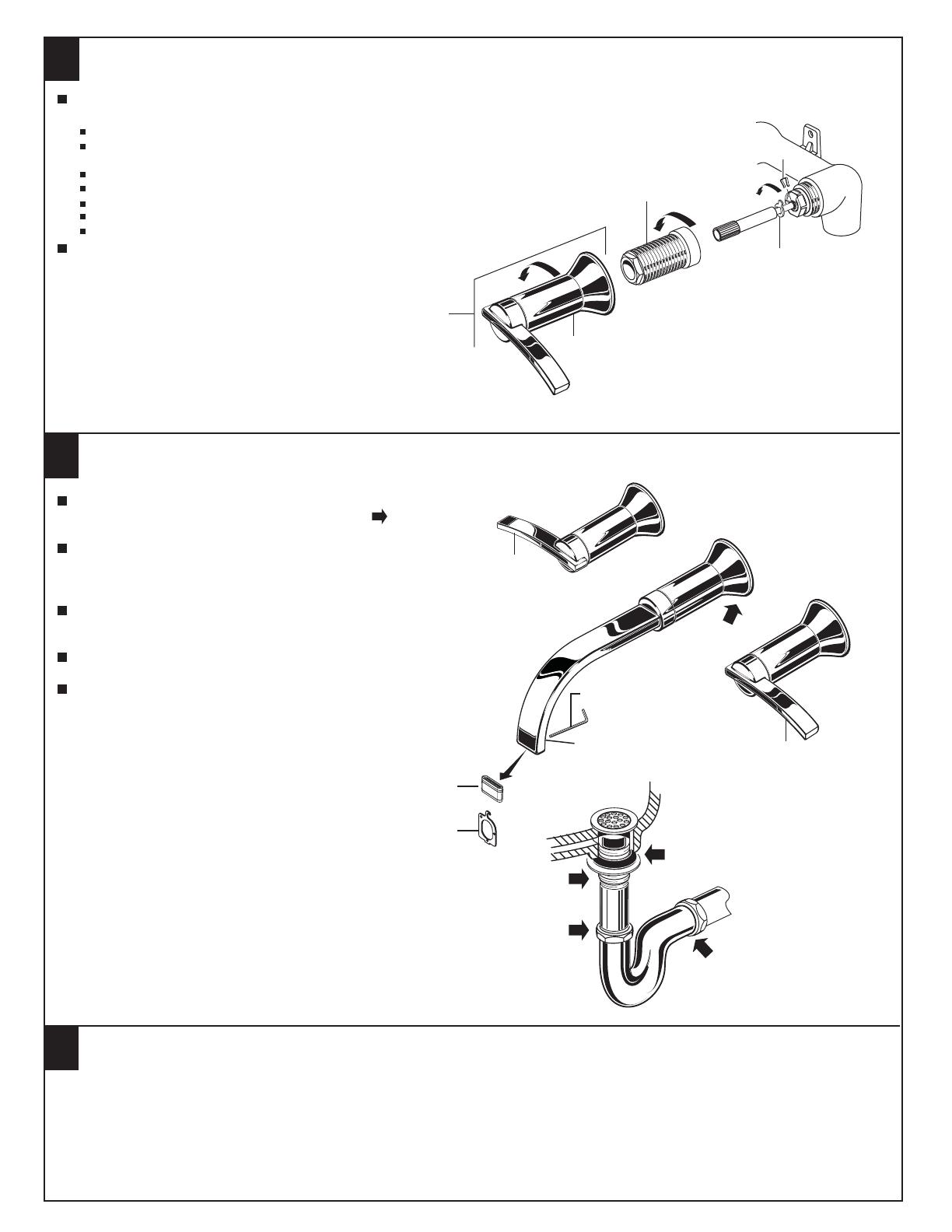
TEST INSTALLED FAUCET
7
TO REMOVE
HANDLE
90˚
5
To change direction of handle rotation,
proceed as follows:
Turn valve to OFF position.
Thread counter-clock wise HANDLE BASE (1) to remove
HANDLE ASSEMBLY (2) from VALVE HOUSING (3).
Thread counter-clock wise VALVE HOUSING (3) to remove.
Use a flat blade screw driver to remove SPRING CLIP (4).
Lift STOP WASHER (5), turn 90˚ and replace.
Replace SPRING CLIP (4).
Reinstall all parts and HANDLE ASSEMBLY (2).
If spout drips, operate handles several times from OFF to ON
position. Do not force - handles turn only 90˚.
SERVICE
3
4
3
2
2
5
4
DO: SIMPLY RINSE THE PRODUCT CLEAN WITH CLEAR WATER. DRY WITH A SOFT COTTON FLANNEL CLOTH.
DO NOT: DO NOT CLEAN THE PRODUCT WITH SOAPS, ACID, POLISH, ABRASIVES, HARSH CLEANERS, OR A
CLOTH WITH A COARSE SURFACE.
CARE INSTRUCTIONS:
1
1
1
With HANDLES (1) in OFF position, turn on water
supplies and check all connections for leaks.
Remove AERATOR (2). First loosen aerator set screw with
HEX WRENCH (3) supplied. Pull out AERATOR (2) with
AERATOR KEY (4).
Operate both HANDLES (1) to flush water
lines thoroughly.
Replace AERATOR (3) and tighten set screw.
Check all dran connections for leaks.
AERATOR
SET
SCREW
1 / 1

American Standard 7430451.295 Installation guide

Category
Sanitary ware
Type
Installation guide

American Standard 7430451.295 is a wall-mount faucet with a sleek and modern design, perfect for contemporary bathrooms. It features a single lever handle for easy control of water temperature and flow, and a high-arc spout for added convenience. The faucet is constructed of durable brass and finished in a corrosion-resistant finish, ensuring long-lasting performance. It is also WaterSense certified, meeting strict criteria for water efficiency without sacrificing performance. Installation is simple and straightforward, with all necessary hardware included.

Ask a question and I''ll find the answer in the document

Finding information in a document is now easier with AI

Ask the document