Page is loading ...

AT-9900 SERIES
Quick Install Guide
AT-9924T
AT-9924SP
AT-9924T/4SP

2 AT-9900 Series Switch
AT-9900 Series Quick Install Guide
Document Number C613-04052-00 REV A.
Copyright © 2004 Allied Telesyn International, Corp.
19800 North Creek Parkway, Suite 200, Bothell, WA 98011, USA.
All rights reserved. No part of this publication may be reproduced without prior
written permission from Allied Telesyn.
Allied Telesyn International, Corp. reserves the right to make changes in
specifications and other information contained in this document without prior
written notice. The information provided herein is subject to change without
notice. In no event shall Allied Telesyn be liable for any incidental, special,
indirect, or consequential damages whatsoever, including but not limited to lost
profits, arising out of or related to this manual or the information contained
herein, even if Allied Telesyn has been advised of, known, or should have known,
the possibility of such damages.
All trademarks are the property of their respective owners.
9900qig.fm Page 2 Thursday, September 2, 2004 9:41 AM

Quick Install Guide 3
Electrical Safety and Emission Compliance Statement
STANDARDS: This product meets the following standards:
Category Approval Agency and Requirement
UL60950-1
CAN/CSA-C22.2 No. 60950-1-03
EN60950-1
EN60825-1
AS/NZS 60950
Electromagnetic Compliance FCC CFR47 Part 15 Class A
EN55022 Class A
VCCI Class A
AS/NZS CISPR22 Class A
CNS 13438 Class A
EN61000-3-2/3
Immunity EN55024
U.S. Federal Communications Commission
RADIATED ENERGY
Note: This equipment has been tested and found to comply with the limits for a Class A digital device
pursuant to Part 15 of the FCC Rules. These limits are designed to provide reasonable protection
against harmful interference when the equipment is operated in a commercial environment. This
equipment generates, uses, and can radiate radio frequency energy and, if not installed and used in
accordance with this instruction manual, may cause harmful interference to radio communications.
Operation of this equipment in a residential area is likely to cause harmful interference in which case
the user will be required to correct the interference at his own expense.
Note: Modifications or changes not expressly approved by the manufacturer or the FCC can void
your right to operate this equipment.
Canadian Department of Communications
This Class A digital apparatus meets all requirements of the Canadian Interference-Causing
Equipment Regulations.
Cet appareil numérique de la classe A respecte toutes les exigences du Règlement sur le matériel
brouilleur du Canada.
9900qig.fm Page 3 Thursday, September 2, 2004 9:41 AM

Quick Install Guide 5
Table of Contents
Electrical Safety and Emission Compliance Statement ............................................. 3
Models Covered By This Guide .................................................................................... 6
Package Contents ............................................................................................................. 6
Selecting a Site ................................................................................................................... 7
How to Install the Switch ............................................................................................... 8
Apply power to the switch ........................................................................................... 12
How to Configure the Switch ..................................................................................... 14
System LEDs .................................................................................................................... 16
Documentation and Tools CD-ROM ......................................................................... 18
Translated Safety Statements ....................................................................................... 19
EC Declaration of Conformity .................................................................................... 40
9900qig.fm Page 5 Thursday, September 2, 2004 9:41 AM

6 AT-9900 Series Switch
Models Covered By This Guide
This Quick Install Guide includes information on these models:
■ AT-9924T/4SP
■ AT-9924T
■ AT-9924SP
You can download Quick Install Guide updates from
http:// www.alliedtelesyn.co.nz/support
.
Package Contents
These items are included with each AT-9900 Series switch:
■ One AT-PWR01 power supply unit (either AC or DC)
■ One AC power cord (AC model)
■ One power cord retaining clip (AC model)
■ One serial cable for connecting the switch to a terminal or PC
■ One 19 inch rack-mount kit
■ One AT-9900 Series Quick Install Guide (which includes statutory and safety
information)
■ One AT-9900 Series documentation and tools CD-ROM (which includes
the complete AT-9900 Series document set and utilities)
■ One warranty card
Included with each AT-9924T/4SP switch is one AT-FAN01 fan only module.
Included with each AT-9924T and AT-9924SP switch is one blanking plate.
Contact your authorised distributor or reseller if any items are damaged or
missing.
9900qig.fm Page 6 Thursday, September 2, 2004 9:41 AM

Quick Install Guide 7
Selecting a Site
You can install the switch in a standard 19-inch rack, on a level surface such as a
desktop or bench, or against a wall using the optional wall-mount kit. How to
install the the switch using the 19-inch rack-mount kit is described below. How
to install the switch using the wall-mount kit is described in the AT-9900 Series
Hardware Reference.
When you install the switch, choose a site that:
■ allows adequate airflow around the switch and its vents.
■ is free of dust and moisture.
■ will maintain an ambient temperature range of 0 º C to 50º C
(32º F to 122º F) and a humidity range of 5% to 80% non-condensing.
■ has a reliable and earthed (grounded) power supply, preferably dedicated
and filtered.
■ does not expose cabling to sources of electrical noise such as radio
transmitters, broadband amplifiers, power lines, electric motors, and
fluorescent fixtures.
■ allows easy access to the switch’s power and cable connections.
■ allows all related network devices to be connected to the switch without
exceeding maximum cable length limitations as specified in the AT-9900
Series Hardware Reference.
■ ensures that when the switch is mounted in a rack, the switch is mounted
evenly to prevent uneven mechanical loading of the rack.
9900qig.fm Page 7 Thursday, September 2, 2004 9:41 AM

8 AT-9900 Series Switch
How to Install the Switch
Warning All AC and DC versions of this equipment must be earthed.
The switch is heavier at the rear than at the front. Therefore, to fully support
the switch in a rack we recommended that you use the supplied 19-inch
rack-mount kit. Using this kit is especially critical if the front mounting flange on
the rack is easily deformed, or the switch is installed in areas subject to shocks
such as earth tremors or heavy vibrations.
Prepare to install the switch
1. Read the safety information
Read the safety information included in this Quick Install Guide. This Quick
Install Guide is also on the Documentation and Tools CD-ROM and you can
download a copy from http:// www.alliedtelesyn.co.nz/support.
2. Gather the tools and equipment you will need
You will need a Phillips #2 screwdriver and cage nuts to attach the brackets
to your rack. Cage nuts are not supplied.
To install a switch with a DC power supply unit, you will need an
appropriate DC power source, DC supply cable, ring connectors, and a
crimp tool.
3. Choose a suitable operating location
Follow the guidelines described in “Selecting a Site” on page 7 to choose a
suitable location.
You can install the switch either in a 19-inch rack, on a flat bench, or against
a wall.
4. Unpack the switch
Verify the package contents. If any items are damaged or missing, contact
your authorised distributor or reseller.
9900qig.fm Page 8 Thursday, September 2, 2004 9:41 AM

Quick Install Guide 9
Follow these steps to install the switch using the 19-inch
rack-mount kit
1. Ensure the rack has sufficient space for the switch and its associated
cables.
2. If necessary, install cage nuts at the front and the rear of the rack.
3. Remove the rubber feet from the switch.
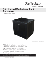
4. Screw the front brackets to the sides of the switch using the supplied
M4 screws (see Figure 1-1 on page 9).
Figure 1-1: Fitting front rack-mount brackets on the switch
5. Measure the depth of the rack to determine the correct position to
attach the rear brackets to the switch.
6. Screw the rear brackets to the sides of the switch using the supplied
M4 screws (see Figure 1-2 on page 10 and Figure 1-3 on page 11).
Front Bracket
Bracket
Rear bracket
A
A
A
Key:
A
screw
Switch
RMOUNT3
A
9900qig.fm Page 9 Thursday, September 2, 2004 9:41 AM

10 AT-9900 Series Switch
Figure 1-2: Fitting rear rack-mount brackets on the switch
RMOUNT4
Right Rear Bracket
A
B
Adjustable bracket
extension
Bracket
A
A
B
Switch
Key:
A
B
screw
nut
9900qig.fm Page 10 Thursday, September 2, 2004 9:41 AM

Quick Install Guide 11
Figure 1-3: Fitting rear rack-mount brackets on the switch
7. Mount the switch into the rack from the front and attach to the rack
using rack mounting screws. Two people may be required to safely
support the switch until the brackets are screwed to the rack.
8. Fit the adjustable bracket extensions onto the rear brackets but do not
tighten the nuts (see Figure 1-2 on page 10 and Figure 1-3 on page 11).
The adjustable bracket extensions are rotationally symmetrical when
attached to the rear brackets. When viewed from the rear of the
switch, the flanges on the bracket extensions are at bottom on the right
and at the top on the left. This is to allow adequate clearance when a
power supply unit or fan only module is removed from the switch.
9. Attach the adjustable bracket extensions to the rack using appropriate
rack mounting screws.
10. Tighten the nuts securing the adjustable bracket extensions to the rear
brackets.
11. Check all screws and nuts to ensure they are fully tightened.
RMOUNT5
Key:
A
B
screw
nut
Adjustable bracket
extension
B
Switch
A
A
B
Left Rear Bracket
9900qig.fm Page 11 Thursday, September 2, 2004 9:41 AM

12 AT-9900 Series Switch
Apply power to the switch
At the rear of the switch are two power supply bays. Your switch comes
pre-installed with one power supply unit (PSU) and either one fan only module
(FOM) or one blanking panel over a power supply bay, depending on the switch
model.
AC power supply unit specifications
Important information for service personnel:
■ CAUTION: double pole/neutral fusing
■ The ratings of fuses FH101 and FH102 is 250 V, 5 A
DC supply cable and power supply specifications
DC supply cable specifications:
■ Three-core cable is required
■ Minimum core size: 3.3 mm
2
(12 AWG) high strand count copper wire
■ Minimum cable rating: 600 V, 90 degrees Celsius
DC power supply specifications:
■ 40 to 60 V, 48 V nominal
■ Supports either positive grounded or negative grounded operation
For circuit protection a 15 Amp certified/Listed circuit breaker is required.
How to apply power to an AC power supply unit
To apply power to the PSU, plug the provided AC power cord into the power
inlet on the faceplate of the PSU and connect the power cord to the main power
supply.
How to apply power to a DC power supply unit
Warning Only trained and qualified personnel should connect a DC power
supply.
Warning For centralized DC power connection, the switch should be installed
only in Restricted Access Areas (Dedicated Equipment Rooms, Equipment
Closets, or the like) in accordance with Articles 110-16, 110-17, and 110-18 of
the National Electrical Code, ANSI/NAPA 70.
Warning Ensure that the supply cable is not live.
9900qig.fm Page 12 Thursday, September 2, 2004 9:41 AM

Quick Install Guide 13
1. Remove the transparent protective terminal cover.
2. Strip the supply cable wires to expose 7.5mm (0.31 in.) of bare
conductor. Terminate with a nylon insulated solderless ring tongue
terminal, JST FN5.5-5 or equivalent, using a crimp tool.
3. Connect the ground wire to the ground terminal. Use the diagram on
the rear panel of the switch to identify terminals. Tighten the terminal
to between 2.4 and 4.0 Nm (21.3 and 35.4 lbf in).
Warning Check that the PSU terminals are wired to the correct polarity. A PSU
will be damaged if incorrectly connected.
4. Connect the positive feed to the + (positive) terminal and the negative
feed to the - (negative) terminal. Tighten the terminals to between 2.4
and 4.0 Nm (21.3 and 35.4 lbf in).
5. Ensure there are no exposed cable strands.
Warning Ensure the transparent plastic terminal cover is replaced.
6. The cover must be replaced before continuing.
7. Secure the supply cable to the rack framework or a similar object to
ensure that connections are isolated from any force applied to the
cable.
8. Ensure the circuit breaker for the supply circuit and the Run/Standby
switch on the PSU are in the Off position. Use a small diameter pin to
operate the Run/Standby switch. When the Run/Standby switch is
pushed out, it is Off.
9. Connect the supply cable wires to the circuit breaker.
10. Push the Run/Standby switch in to the On position using a small
diameter pin.
Confirm that the switch is receiving power
Check that at least one of the PSU LEDs on the switch’s front panel is lit green.
If the LEDs fail to light, refer to the AT-9900 Series Hardware Reference for
troubleshooting information.
9900qig.fm Page 13 Thursday, September 2, 2004 9:41 AM

14 AT-9900 Series Switch
How to Configure the Switch
Some configuration is necessary to enable the switch’s advanced switching
capabilities. This is achieved via the Command Line Interface (CLI).
Using the CLI to configure a switch
1. Connect a terminal or PC to RJ-45 (ASYN0)
Use a RJ-45 straight-through cable to connect your terminal or PC to the
RS-232 terminal port on the switch’s front panel.
2. Set the communication parameters
Set the communication parameters on your terminal or terminal emulation
program to:
• Bit rate: 9600
• Data bits: 8
•Parity: None
• Stop bits: 1
• Flow control: Hardware
3. Check the power supply
For AC models, ensure that the switch is receiving power (PWR LED is lit
green).
For DC models, ensure that the Run/Standby switch is in the On or Run
position and that the switch is receiving power (PWR LED is lit green).
4. Log in
After the switch has booted, the login prompt appears. If the login prompt
does not appear, press [Enter] two or three times.
When the switch boots for the first time it automatically creates an
account with manager privileges. The account has the login name manager
and the password is friend.
At the login prompt, enter the login name and password:
Login: manager
Password: friend
The switch’s command prompt appears. Now use the CLI to configure the
switch.
9900qig.fm Page 14 Thursday, September 2, 2004 9:41 AM

Quick Install Guide 15
5. Change password and display help
Change the password as soon as possible because a manager account left
with the default password is a serious security risk. Remember the new
password as there is no way to retrieve it if it is lost.
To change the account password, use the command:
set password
To display a list of help topics, use the command:
help
To display help on a specific topic, use the command:
help topic
Alternatively, type a question mark (?) at the end of a partially completed
command to see a list of valid options.
How to configure the switch is explained in detail in the AT-9900 Series Software
Reference.
9900qig.fm Page 15 Thursday, September 2, 2004 9:41 AM

16 AT-9900 Series Switch
System LEDs
How the LEDs on AT-9900 Series switches report faults and operational
activities are described in Table 1-1 on page 16.
How the LEDs on power supply units (AT-PWR01) and fan only modules
(AT-FAN01) report faults and operational activities are described in Table 1-2 on
page 17.
Ethernet port and Small Form Factor Pluggable (SFP) port LEDs are described in
the AT-9900 Series Hardware Reference.
Table 1-1: System LEDs on all AT-9900 Series switches
LED State Function
PSU 1 Green PSU 1 is installed and supplying power to the
switch, and the voltage output is within
specification.
Red PSU 1 is installed in the switch and either a fan
has failed, or the PSU has exceeded its
recommend temperature threshold of 75º C
(167º F).
A FOM is installed in the switch and a fan has
failed.
The bay is empty.
Not lit A FOM is installed and the fan is good.
PSU 2 Green PSU 2 is installed and supplying power to the
switch, and the voltage output is within
specification.
Red PSU 2 is installed in the switch and either a fan
has failed, or the PSU has exceeded its
recommend temperature threshold of 75º C
(167º F).
A FOM is installed in the switch and a fan has
failed.
The bay is empty.
Not lit A FOM is installed and the fan is good.
9900qig.fm Page 16 Thursday, September 2, 2004 9:41 AM

Quick Install Guide 17
Fault Red The switch or management software is
malfunctioning.
1 Flash One or more heatsink fans has failed or is
operating below the recommended speed.
6 Flashes
a
The switch’s temperature has exceeded the
recommended threshold.
Slow
flashing at
startup
The SDRAM (DIMM) has not been detected.
Rapid
flashing at
startup
The SDRAM (DIMM) is not compatible with
the switch.
CF Green The CompactFlash memory is active. Do not
eject the flash memory module.
a. If the switch exceeds the temperature alarm threshold the fault LED will flash six times,
turn off for a short period, and then repeat the flashing sequence.
Table 1-2: LEDs on the AT-PWR01 and AT-FAN01
LED State Function
Fault Red There is either a fan failure, or the
temperature has exceeded the limit of 70º C
(158º F).
PWR Green A PSU is installed in the switch and is receiving
power. A FOM does not have this LED.
Table 1-1: System LEDs on all AT-9900 Series switches (Continued)
LED State Function
9900qig.fm Page 17 Thursday, September 2, 2004 9:41 AM

18 AT-9900 Series Switch
Documentation and Tools CD-ROM
The documentation and tools CD-ROM bundled with each switch contains the
complete documentation set for AT-9900 Series switches and their expansion
options, as well as tools to manage the switch.
The documentation and tools CD-ROM includes:
■ The AT-9900 Series Hardware Reference, which provides detailed information
on the switch unit and its hardware features.
■ The AT-9900 Series Software Reference, which provides detailed information
on configuring the switch unit and its software.
■ The AT-PWR01 Quick Install Guide, which describes how to install power
supply units and fan only modules in your switch and includes statutory and
safety information.
■ This Quick Install Guide.
■ AT-TFTP Server for Windows for downloading software releases.
■ Adobe Acrobat Reader for viewing online documentation.
9900qig.fm Page 18 Thursday, September 2, 2004 9:41 AM

Quick Install Guide 19
Translated Safety Statements
!1Safety
WARNING: In a domestic environment this product may cause radio
interference in which case the user may be required to take adequate measures.
WARNING: Class 1 Laser product.
WARNING: Do not stare into the laser beam.
CAUTION: Use of controls or adjustments of performance or procedures
other than those specified herein may result in hazardous radiation exposure.
ELECTRICAL NOTICES
WARNING: ELECTRIC SHOCK HAZARD
To prevent ELECTRIC shock , do not remove the cover. No user-serviceable
parts inside. This unit contains HAZARDOUS VOLTAGES and should only be
opened by a trained and qualified technician.
LIGHTNING DANGER
DANGER: DO NOT WORK on equipment or CABLES during periods of
LIGHTNING ACTIVITY.
CAUTION: POWER CORD IS USED AS A DISCONNECTION DEVICE. TO
DE-ENERGIZE EQUIPMENT, disconnect the power cord.
ELECTRICAL - TYPE CLASS 1 EQUIPMENT
THIS EQUIPMENT MUST BE EARTHED. Power plug must be connected to a
properly wired earth ground socket outlet. An improperly wired socket outlet
could place hazardous validates on accessible metal parts.
PLUGGABLE EQUIPMENT, the socket outlet shall be installed near the
equipment and shall be easily accessible.
CAUTION: Air vents must not be blocked and must have free access to the
room ambient air for cooling.
OPERATING TEMPERATURE: This product is designed for a maximum
ambient temperature of 50 degrees C.
ELECTRICAL - AC MAINS CIRCUIT OVERLOADING
When installing product, consideration must be given to the accumulative
nameplate ratings when connecting the equipment to the AC supply wiring.
CAUTION: MECHANICAL LOADING - Mounting of the equipment in the
rack should be such that a hazardous condition is not achieved due to uneven
loading.
Lithium Battery - Should only be changed by authorised service personnel.
CAUTION: Danger of explosion if battery incorrectly replaced. Replace only
9900qig.fm Page 19 Thursday, September 2, 2004 9:41 AM

20 AT-9900 Series Switch
with Lithium Battery, type CR2032, and dispose of in accordance with the
manufacturer’s recommendations and all local codes.
ALL COUNTRIES: Install product in accordance with local and National
Electrical Codes.
WARNING: For centralized DC power connection, install only in a restricted
access area.
A tray cable is required to connect the power source if the unit is powered by
centralized DC power. The tray cable must be UL listed Type TC tray cable and
rated at 600 V and 90 degree C, with three conductors, minimum 12 AWG.
WARNING: Only trained and qualified personnel are allowed to install or
replace this equipment.
WARNING: As a safety precaution, a 15 Amp circuit breaker should be
installed at the supply end of the cable to be used with this LAN equipment.
Always connect the wiring to the LAN equipment first before connecting the
wiring to the breaker. To avoid the danger of physical injury from electrical
shock, do not work with HOT feeds. Always be sure that the breaker is in the
OFF position before connecting the wiring to the breaker.
WARNING: Do not strip more than the recommended amount of wire.
Stripping more than the recommended amount can create a safety hazard by
leaving exposed wire on the terminal block after installation.
WARNING: When installing this equipment, always ensure that the frame
ground connection is installed first and disconnected last.
WARNING: “Safety Hazard” - Check to see if there are any exposed
copper strands coming from the installed wires. When this installation is done
correctly there should be no exposed copper wire strands extending from the
terminal block. Any exposed wiring can conduct harmful levels of electricity to
persons touching the wires.
DC versions of this system will work with a positive grounded or negative
grounded DC system.
!2Sicherheit
WARNUNG: Bei Verwendung zu Hause kann dieses Produkt Funkstörungen
hervorrufen. In diesem Fall müßte der Anwender angemessene
Gegenmaßnahmen ergreifen.
WARNUNG Laserprodukt der Klasse 1.
WARNUNG Nicht direkt in den Strahl blicken.
9900qig.fm Page 20 Thursday, September 2, 2004 9:41 AM

40 AT-9900 Series Switch
EC Declaration of Conformity
We: ALLIED TELESYN RESEARCH LIMITED
27 NAZARETH AVENUE
CHRISTCHURCH 8002
NEW ZEALAND
Declare under our sole legal responsibility that the following product meets the
safety, protection and conformity requirements of council directives 73/23/EEC
and 89/336/EEC, as amended by 93/68/EEC, on the approximation of the laws of
member states relating to electromagnetic compatibility, electrical safety and the
mutual recognition of conformity of telecommunications terminal equipment
AT-9900 SERIES SWITCHES
to which this declaration relates are in conformity with the following relevant
harmonized standards, the reference numbers of which have been published in
the Official journal of the European community.
EN55022: 1998 Information Technology Equipment—Radio disturbance
EN55024: 1998 Information Technology Equipment—Immunity characteristics—
Limits and methods of measurement.
EN60950-1: 2001 Information Technology Equipment including electrical business
equipment—General Requirements.
EN60825-1: 1994 Safety of Laser Products - part 1: Equipment classification,
requirements and user’s guide.
EN61000-3-2: 2000 Electromagnetic compatibility (EMC) - part 3-2: Limits for
harmonic current emissions (equipment input current up to and
including 16A per phase).
EN61000-3-3: 1995 Electromagnetic compatibility (EMC) - part 3-3: Limitation of
voltage fluctuations and flicker in low-voltage supply systems for
equipment with rated current up to 16A.
Name: Craig Thornton
On behalf of the Manufacturer
Position: Engineering Manager
Signature: Date: 11th August 2004
9900qig.fm Page 40 Thursday, September 2, 2004 9:41 AM
/